How to use WS2812 “NeoPixel” LEDs with a PIC microcontroller
July 12, 2021 • tutorial
Do you want to step up your LED game? Then look no further! The WS2812 “NeoPixel” RGB LEDs are intelligent, individually addressable LED modules. And the best part: Besides two wires for power they only require one data line for as many LEDs as you could want. And today we will learn how to use the WS2812 LED with a PIC microcontroller.
Does this picture look familiar to you? When working with standard LEDs this is usually what happens:
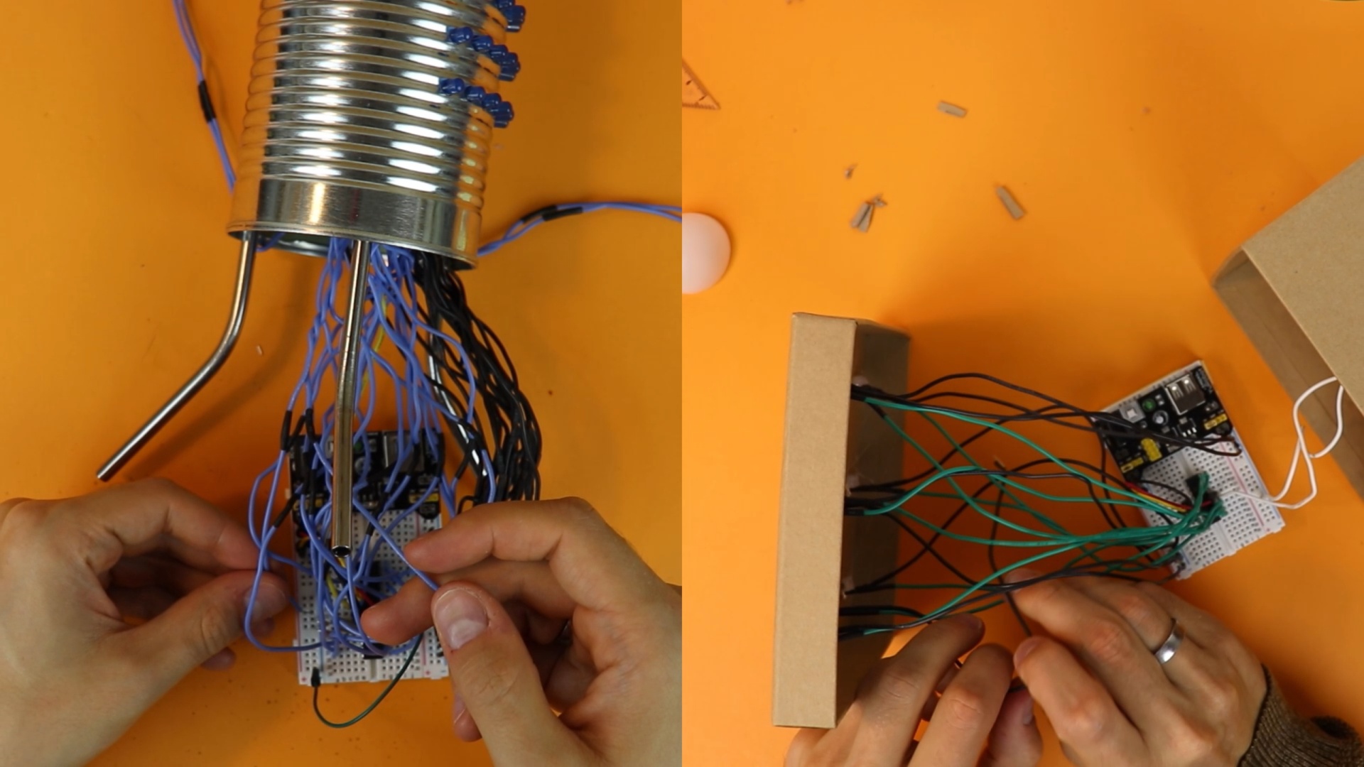
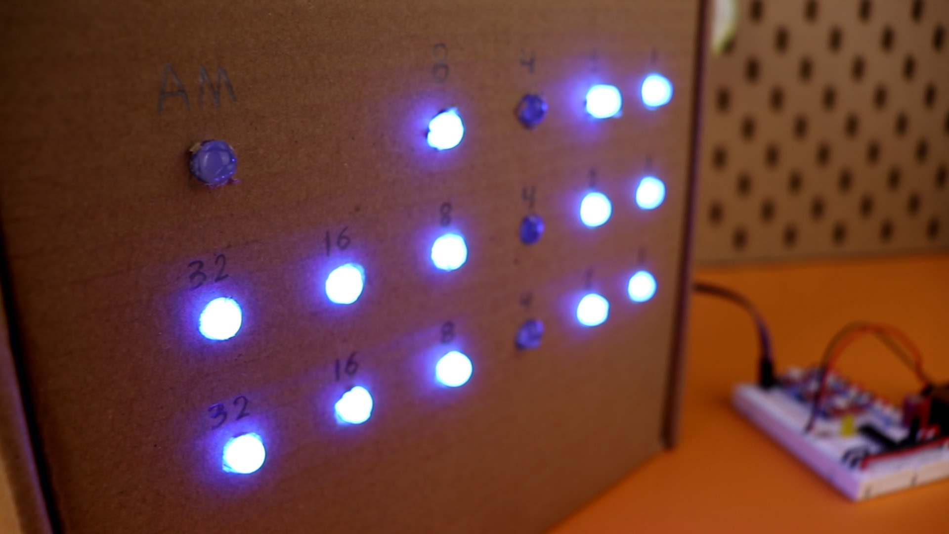
These two projects are the binary clock (left) and the electronic dice (right) that we have built on this channel using conventional LEDs, and they involve a lot of wiring. I personally don't mind it that much, but it can get a bit messy. This is where the WS2812 LEDs come in
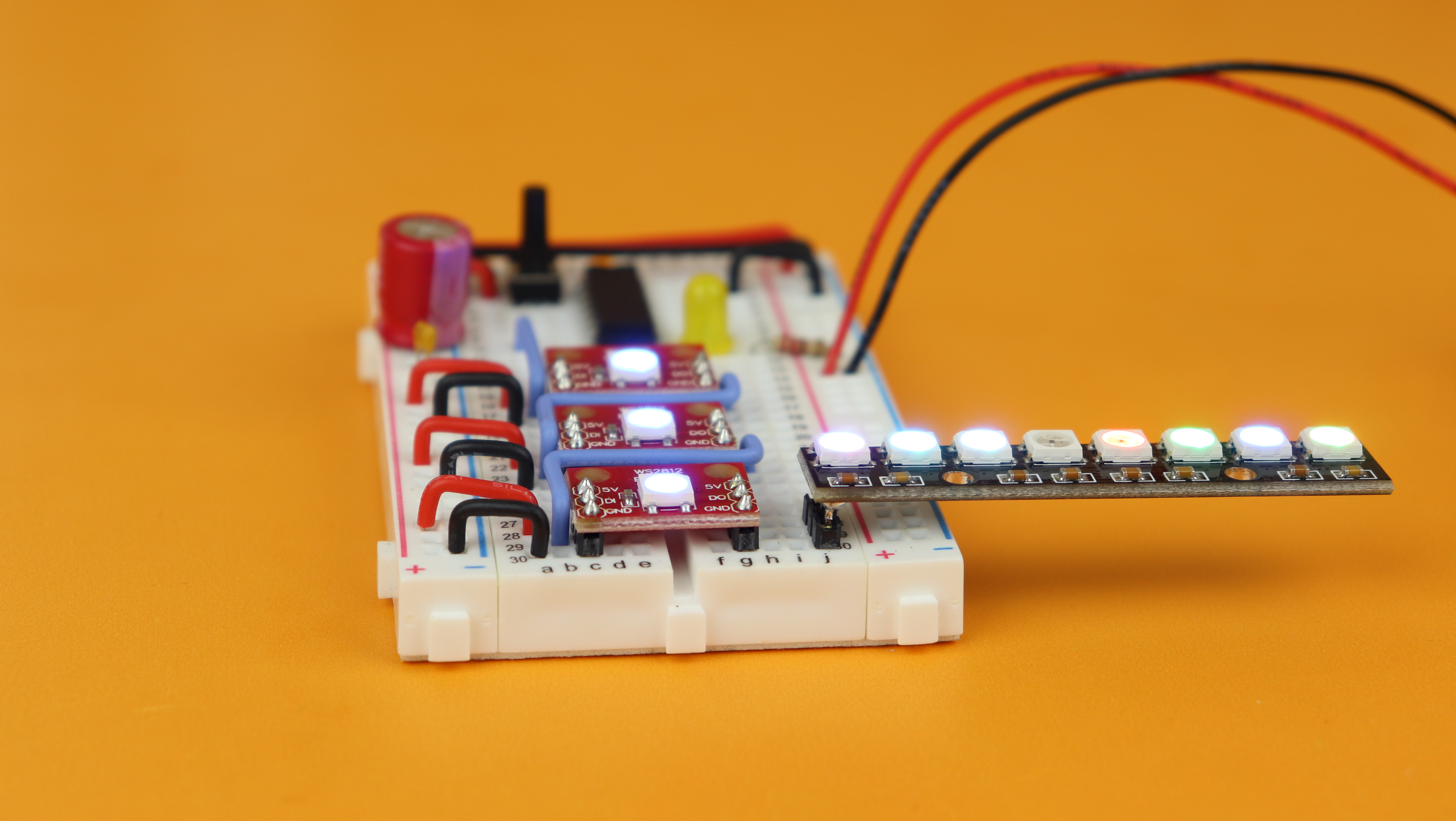
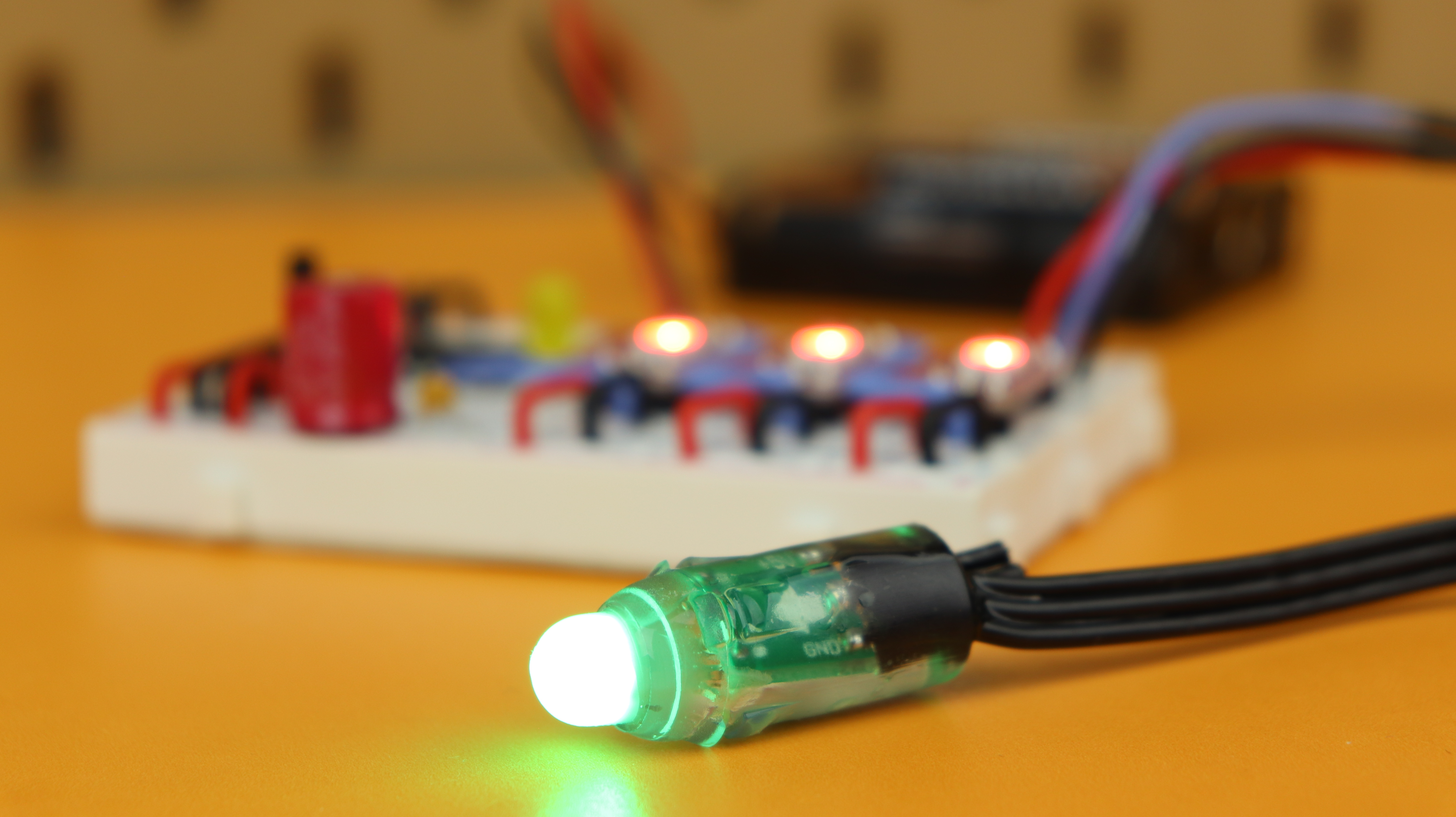
And here is a quick sneak peek for the final result of this tutorial:
What you need
As always you can find a detailed list of all components in the components box in this article :) Here is a picture:
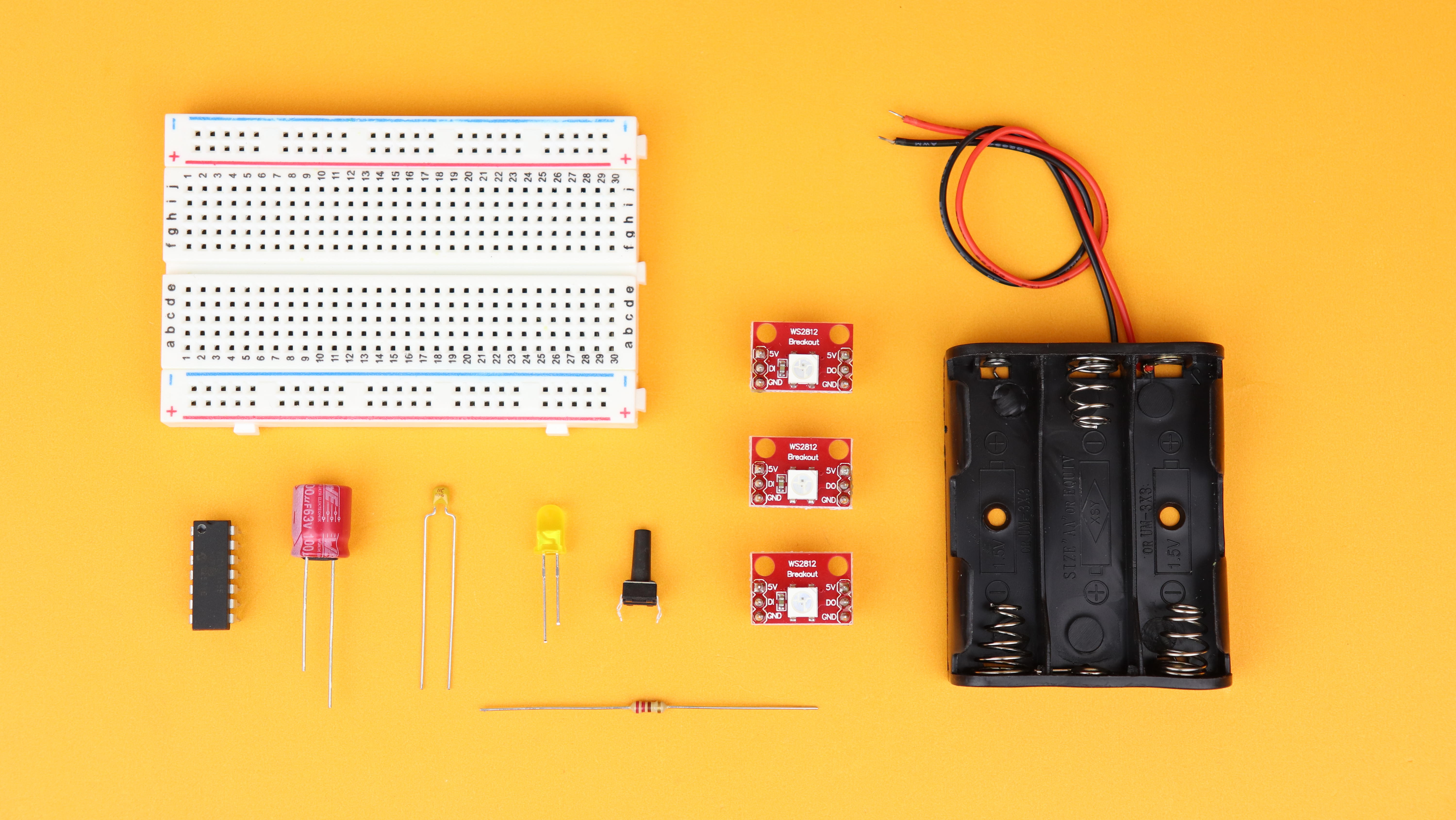
All of these components are pretty common, except for the PIC16F1455 microcontroller. This tutorial is written specifically for that chip, but you can easily order it online for not a lot of money.
WS2812 in a nutshell
Here is a picture of a typical WS2812 LED:

When you zoom in you can see that a WS2812 NeoPixel LED is actually a combination of a red, green, and blue LED, together with a driver chip. Each module has four connections:
- Two power supply pins (VDD and ground),
- a data input,
- and a data output.
The best part is that you can control an unlimited amount of these LEDs using just one microcontroller pin that connects to the data input of the first LED (see more below). Then you just connect the data output to the input of the next LED, and so on. And because these LEDs run at around 5V, you can easily drive them from the same power source as your microcontroller, just make sure your power supply has enough current, because each LED needs 60mA at full brightness.
The WS2812 LEDs come in a lot of different form factors, here is a 8x module:

And here is a popular WS2812 LED chain:
So they only use one wire to receive all their color and brightness information, so let's understand how they work!
WS2812 data protocol
All three LED's inside the WS2812 have 256 brightness levels, which is 8 bit each. So we need to send three 8-bit values for the green, red, and blue values over the data line, one after the other, in this sequence:
G7-G6-G5-G4-G3-G2-G1-G0-R7-R6-R5-R4-R3-R2-R1-R0-B7-B6-B5-B4-B3-B2-B1-B0
Such data protocols with only one data line, and no separate clock line, are called asynchronous, and the timing is very important for them. This is kind of similar to the RS232 protocol, in case you were wondering :)
So each of these 24 bits can be 1 or 0, and the protocol for transferring a single bit is this:
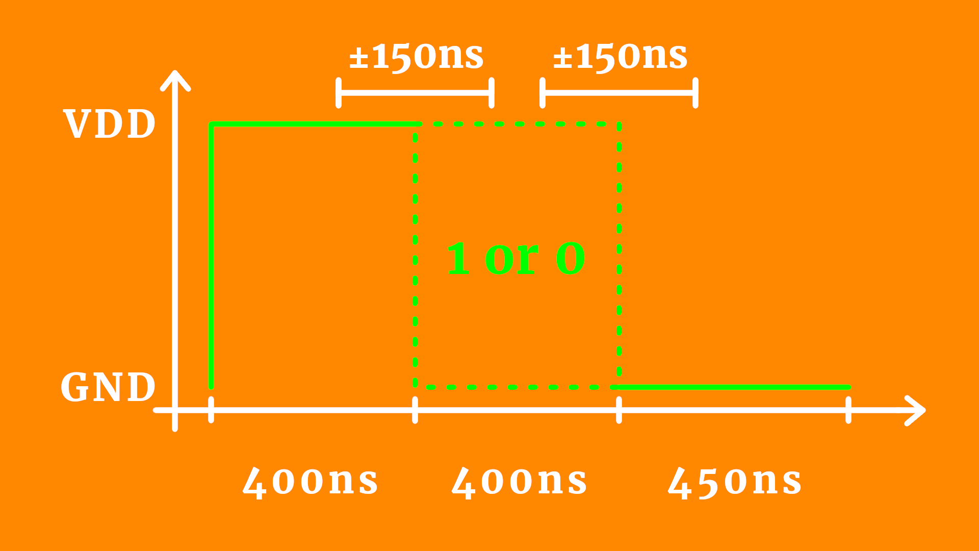
So a 1 is sent by a 800ns high-pulse and a 450ns low signal, and a 0 is sent by a 400ns high-pulse and a 850ns low signal. So you see that the bit information is indeed encoded in the middle 400ns period.
Now this has to be sent out 24 times in a row, without any major delays. If at any time you wait longer than 50 microseconds, then the WS2812 protocol resets and you have to start all over again.
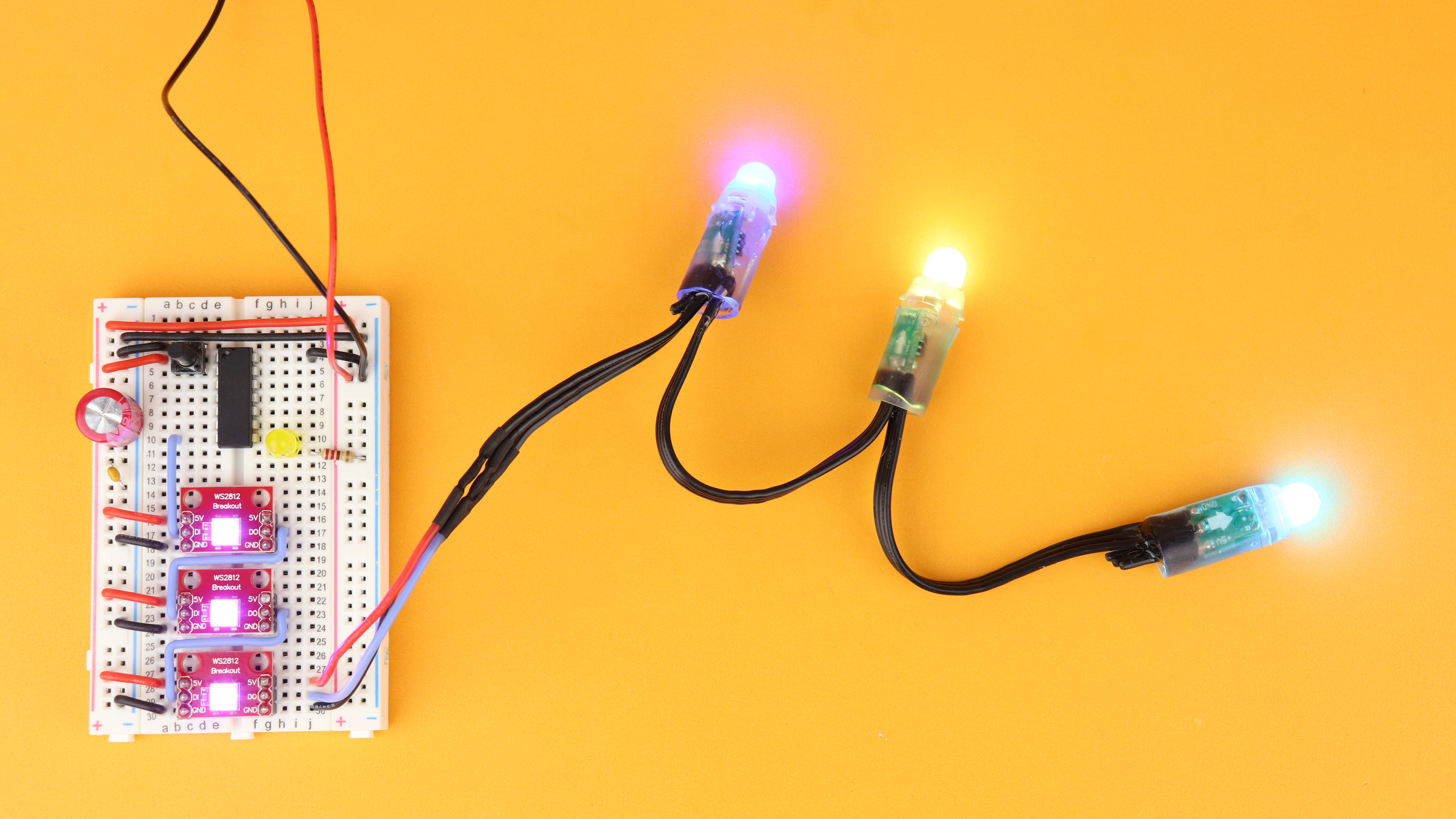
But what if you want to address multiple WS2812 LED modules, like in this picture here?
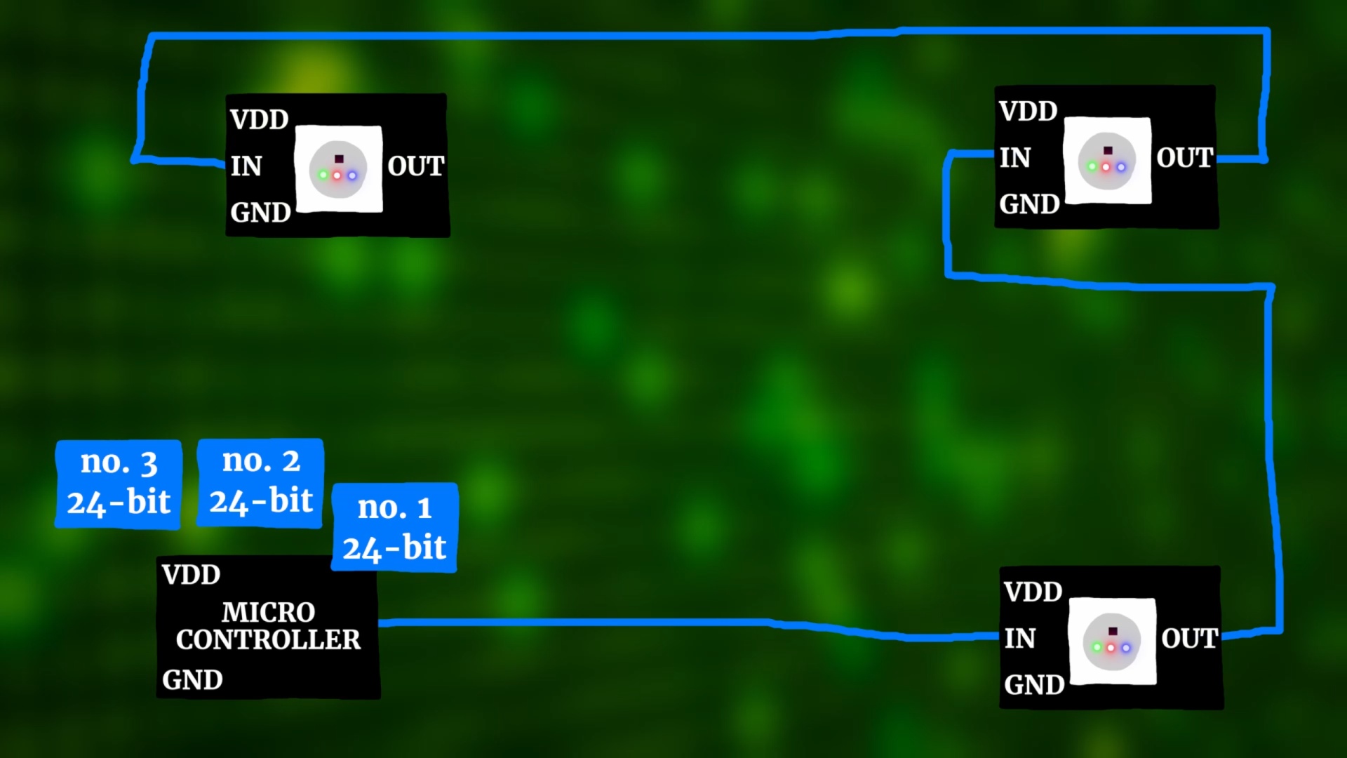
Well, then you just have to send out multiple 24-bit packages, one after the other :) The only thing to keep in mind is that the first LED in the chain keeps the first 24-bit package, and then passes down the line anything else that follows after that. So if you want these three LED modules to be purple, green, and yellow, you need to send a purple 24-bit package first, then a green one, and then the yellow one.
Schematic
With the general idea of the WS2812 protocol out of the way it's time to have a look at the schematic for this tutorial:
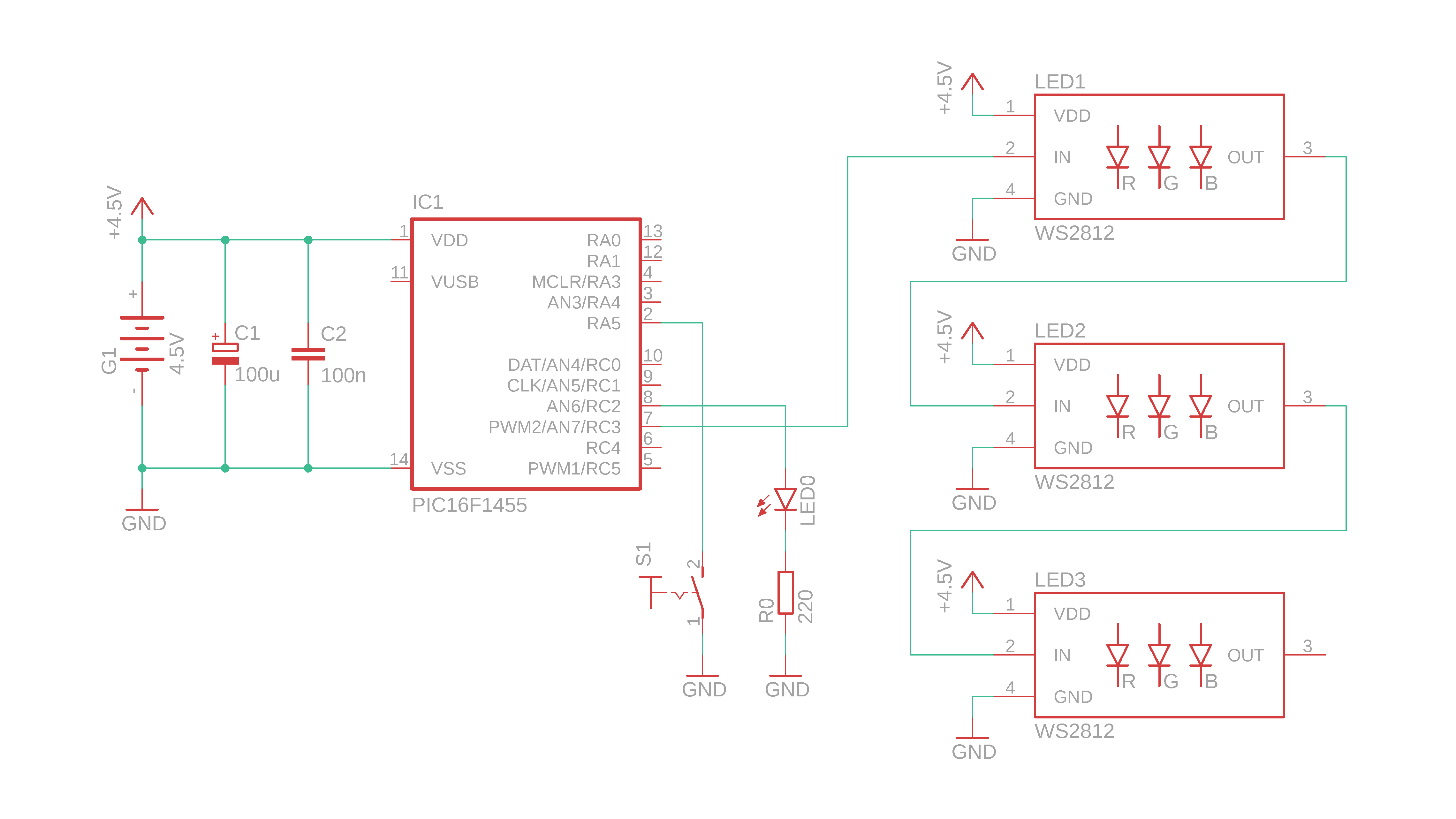
- IC1 is the PIC16F1455 that controls the WS2812 LEDs, and here we just use three of them but you could use many more if you want. The data signal comes from pin RC3 and travels through all three LEDs.
- LED0 at pin RC2 is just there for testing so that we can check if our PIC is really running at the speed at which we want it to run, more on that later.
- We will use the pushbutton S1 to adjust the brightness of our WS2812 LEDs.
- G1 is the battery pack, C1 is a bulk capacitance and C2 is a bypass capacitor for stability.
After building this circuit we will also have to attach the PICkit3 like this:
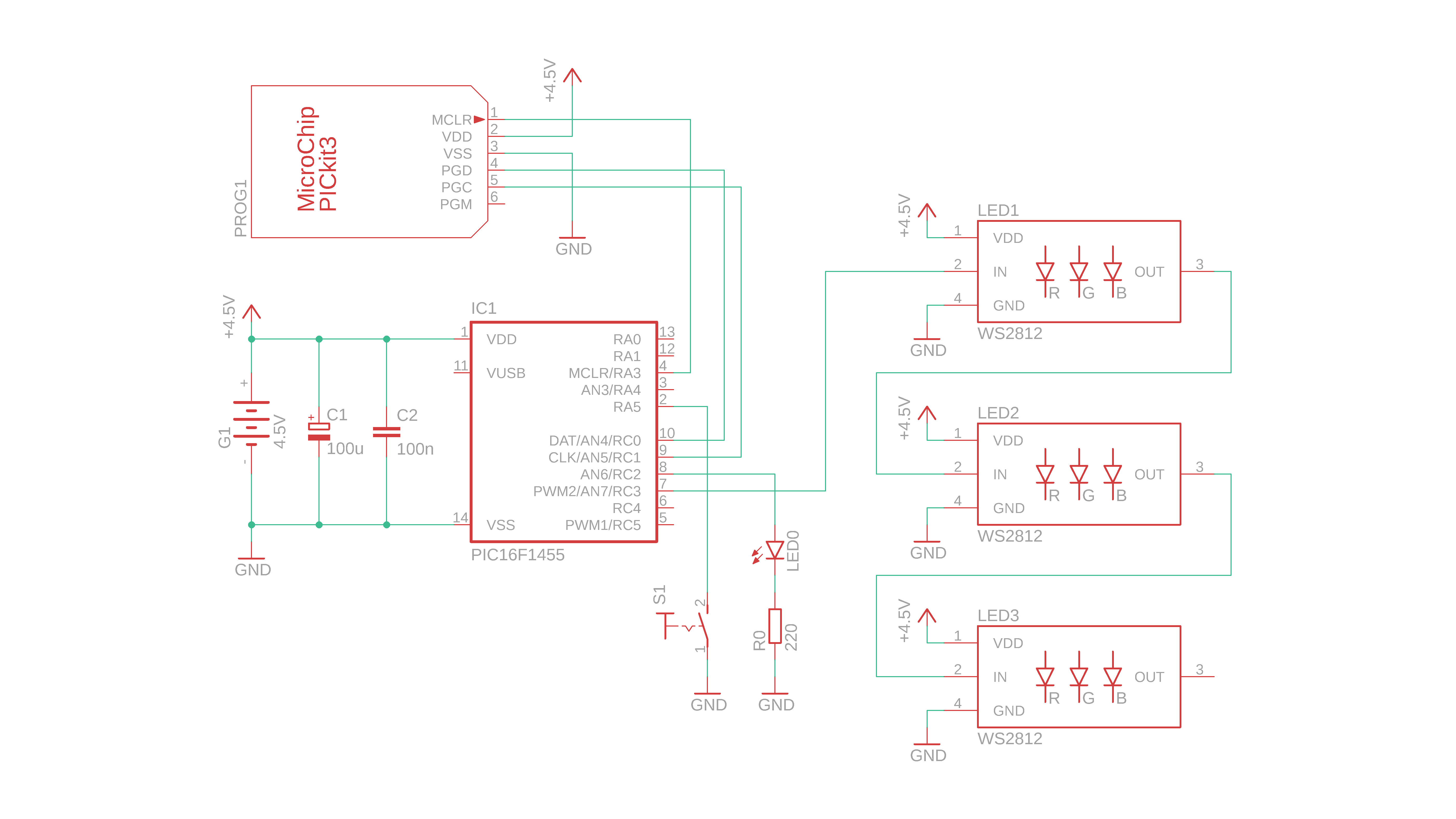
But don't worry, we'll get back to how to flash the controller below.
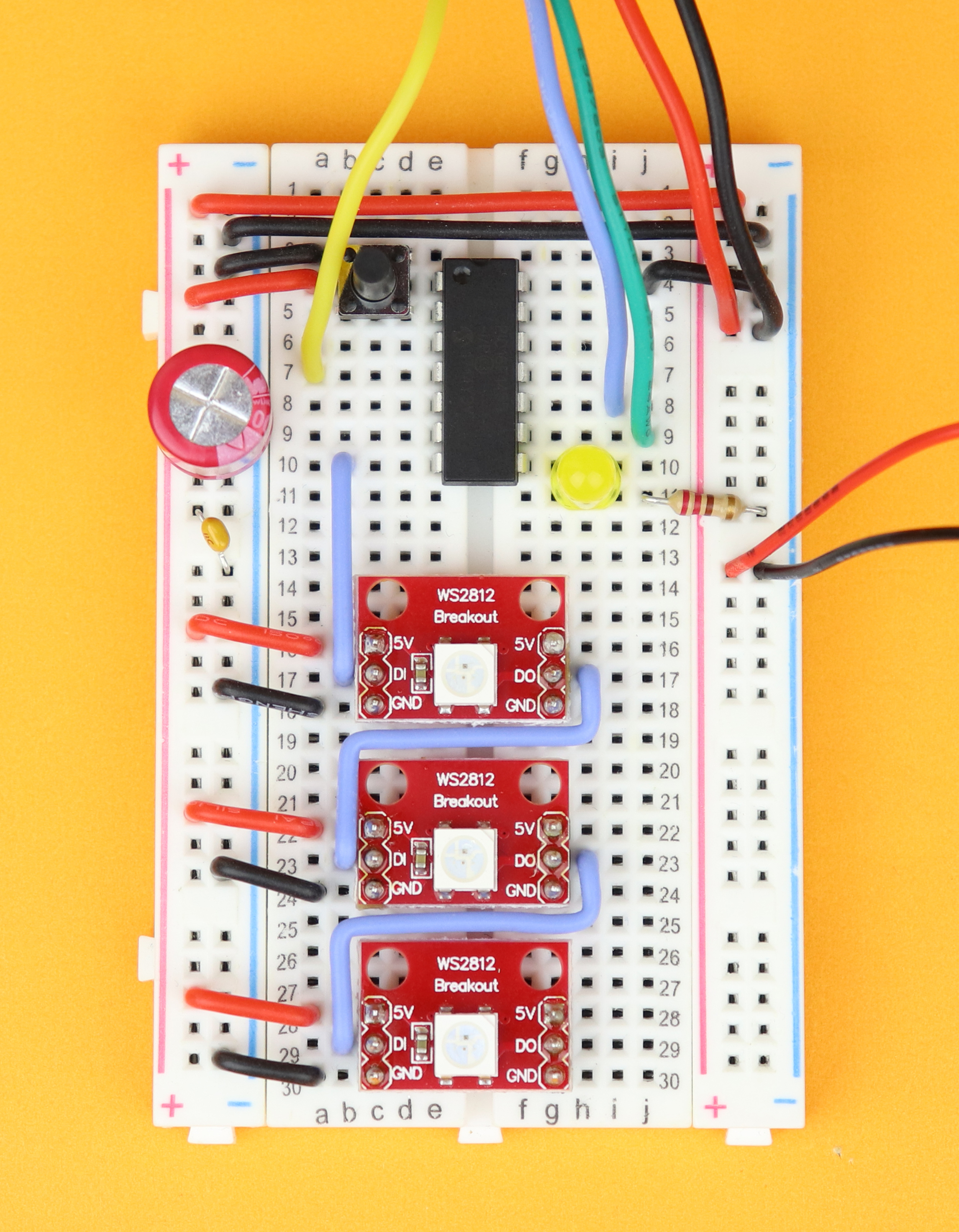
Construction
Okay, let's go ahead and build this thing!
-
-
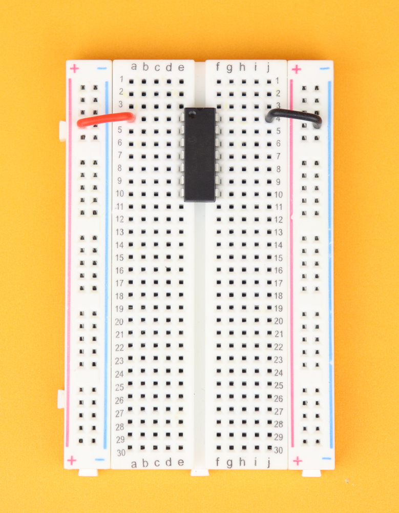
Step 1
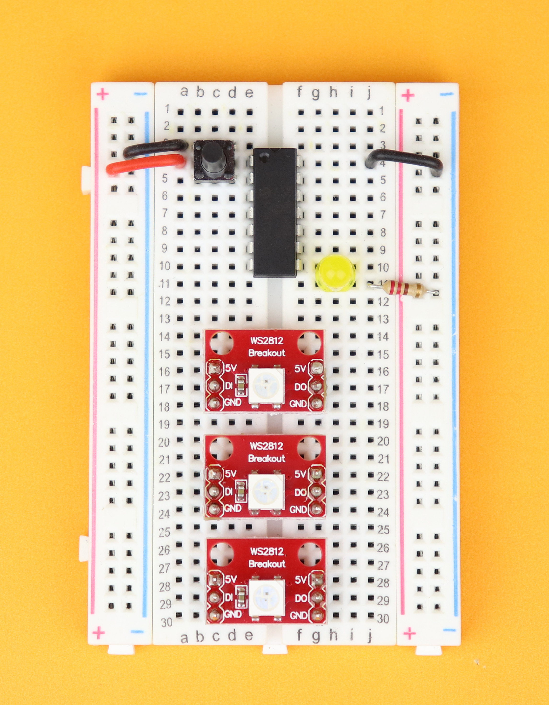
Place the breadboard in front of you, with row 1 facing to the top. Place the PIC16F1455 in row 4, and make sure the notch points towards row 1 of the breadboard. Connect pin 1 to the positive power rail, and pin 14 to the negative power rail.
-
-
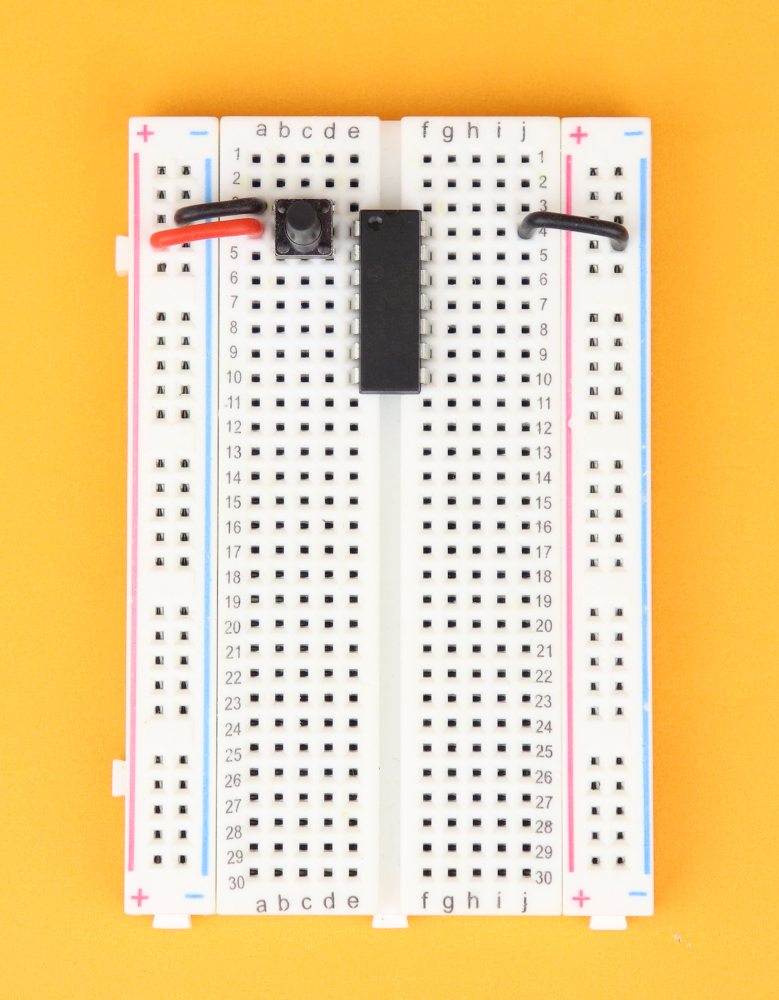
Step 2
Insert the pushbutton between rows 3 and 5, and connect the upper terminal of the pushbutton in row 3 to ground.
-
-
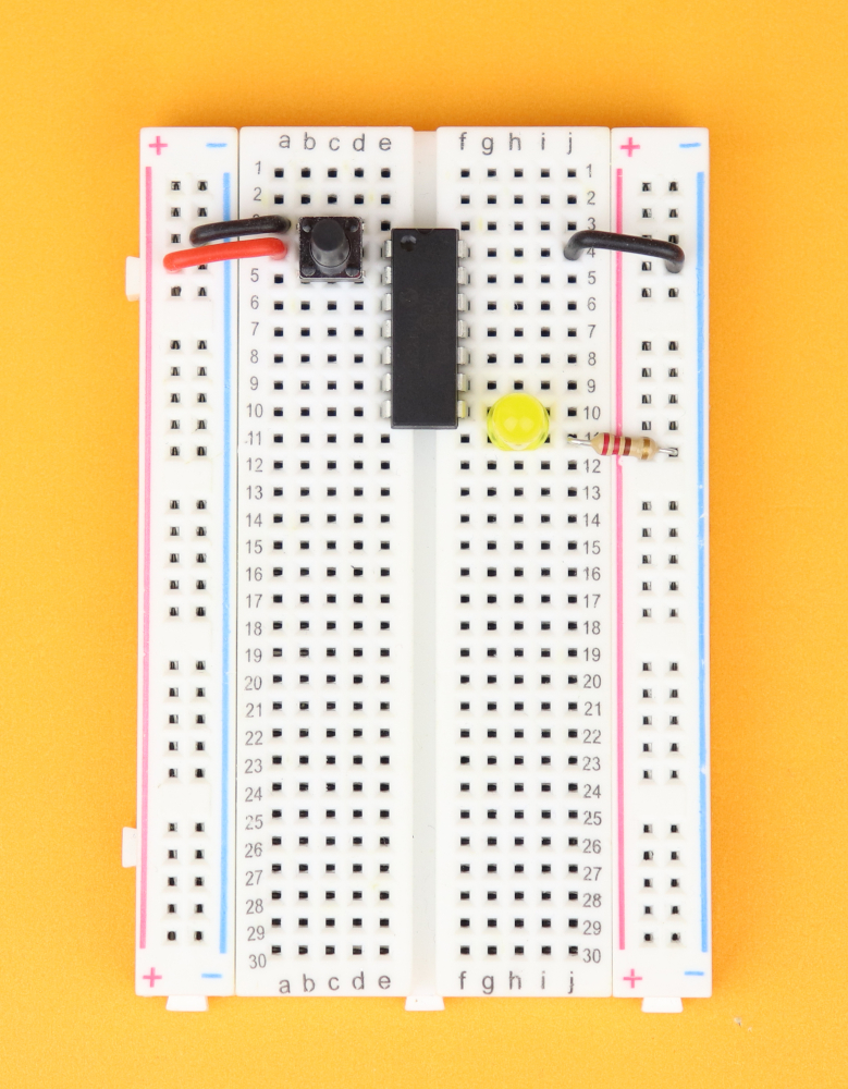
Step 3
Insert LED0 at pin 8 with the cathode in row 11, and connect it to ground with R0.
-
-
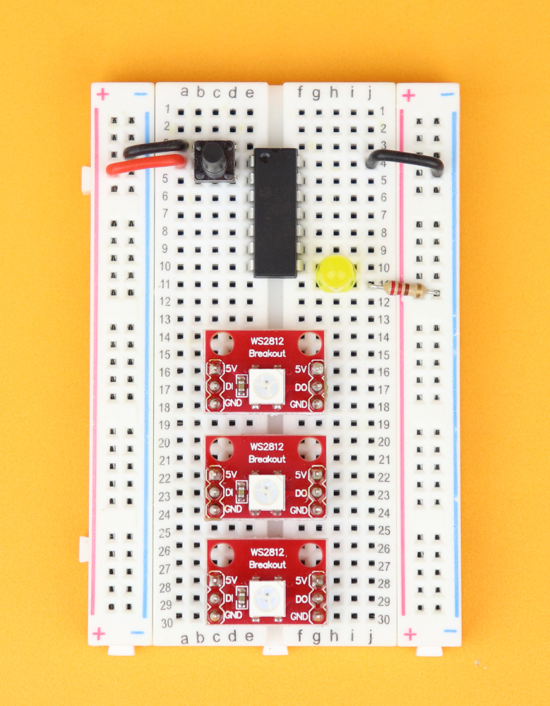
Step 4
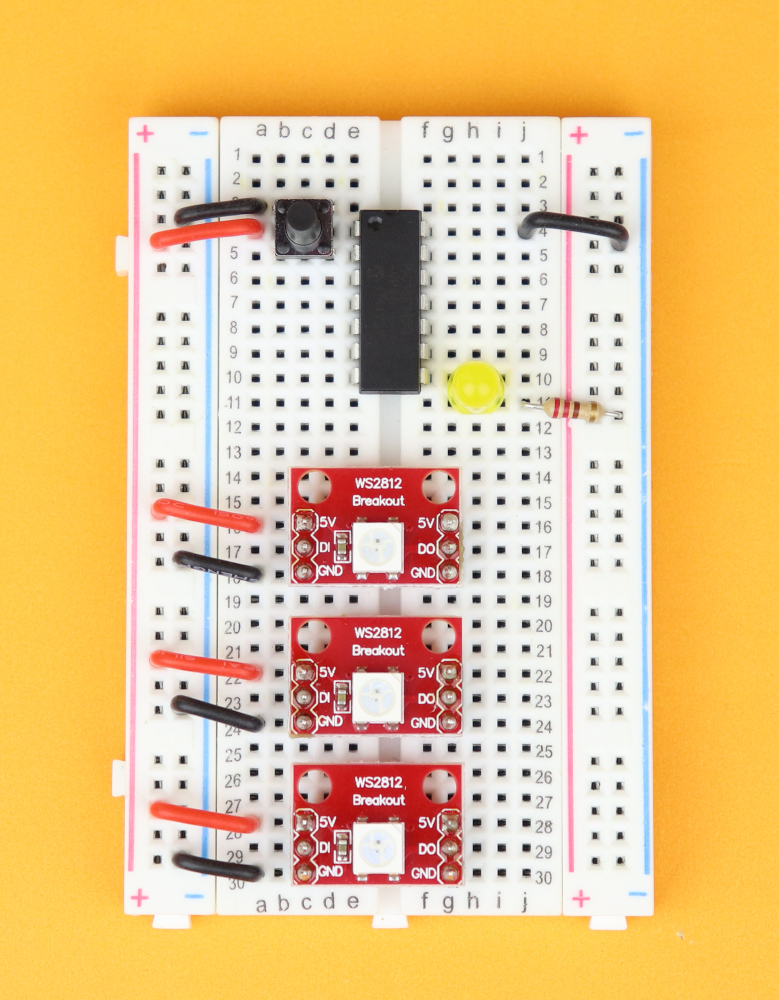
Insert the three WS2812 LED modules in rows 16, 22, 28.
-
-
Step 5
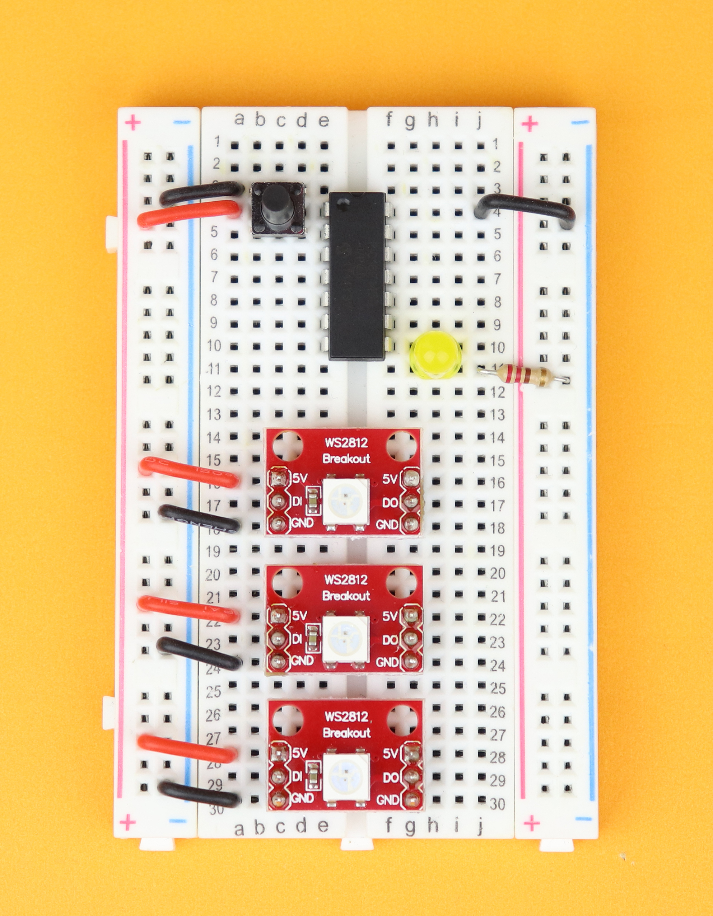
Connect them to the power rail.
-
-
Step 6
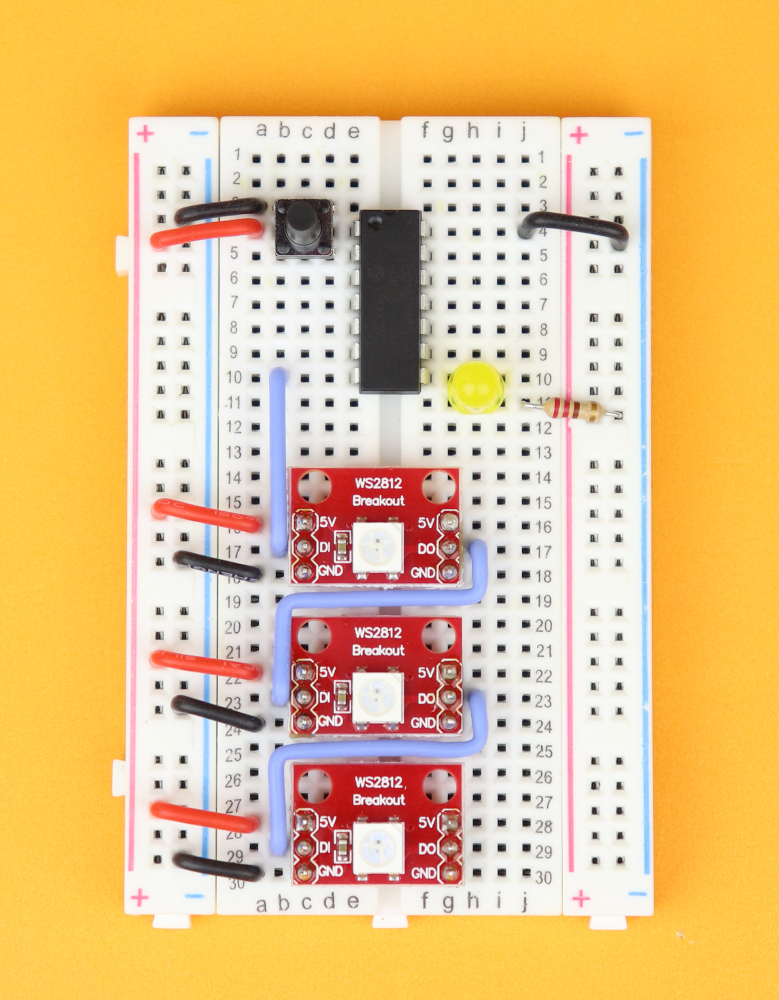
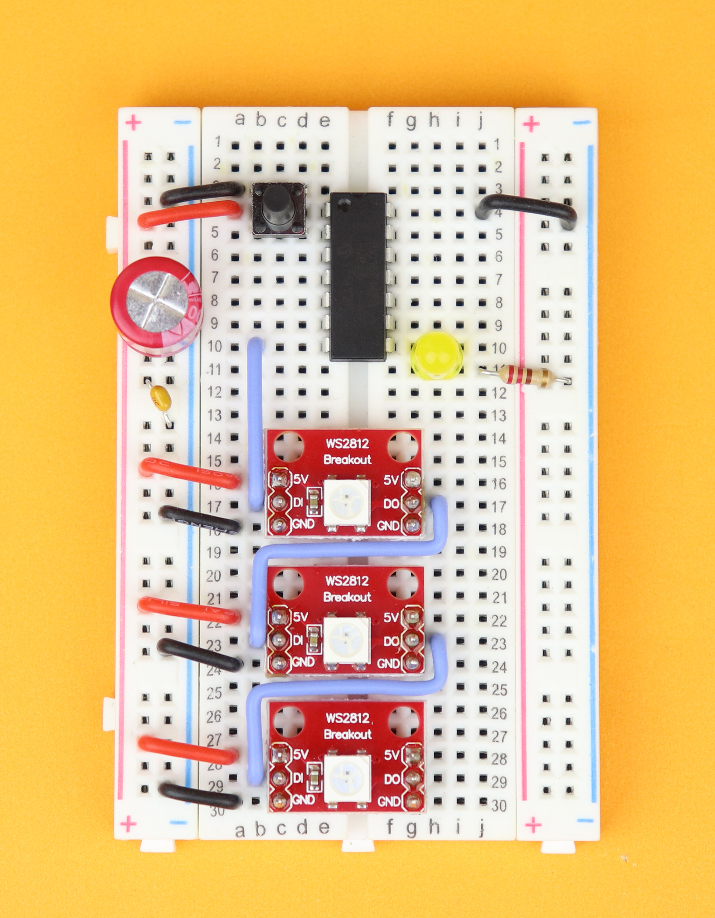
Connect the data lines. Pin 7 of the PIC16F1455 goes to the first module, and then connect the data output of each module to the data input of the next one.
-

-
Step 7
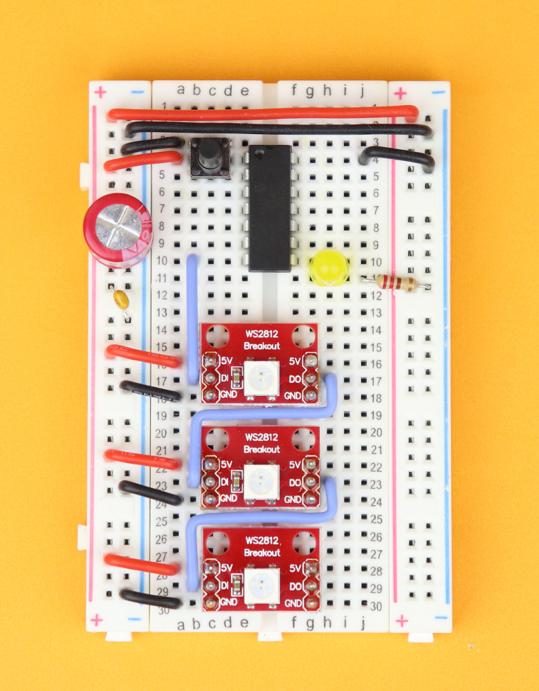
Insert C1 in the power rail, and make sure its negative terminal is connected to the blue negative power rail.
-

-
Step 8
Insert the bypass capacitor C2 in the power rail, you can plug it in either way.
-
-
Step 9
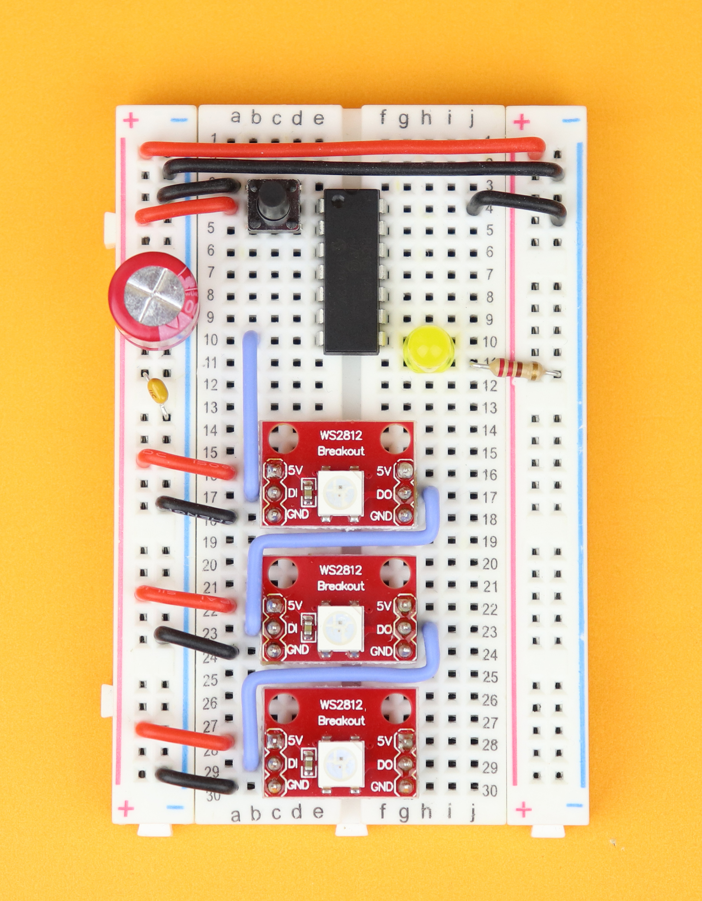
Connect both positive power rails together, and also the negative ones.
-
-
Step 10
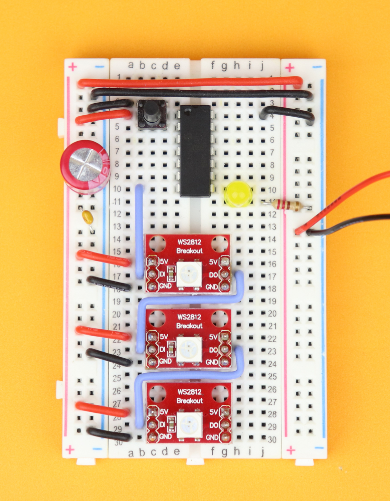
Connect the 4.5V battery pack to the power rail.
-

-
Step 11
Connect the PICkit3. VDD and ground are connected to the power rail, master clear (yellow) goes into pin 4, program data (blue) into pin 10, and program clock (green) into pin 9.


Setting up MPLAB X IDE and IPE
As always, we use the freely available MPLAB X IDE and IPE to program and flash our PIC microcontroller. If you are completely new to PIC microcontrollers this process can be bit daunting, I know, but it's totally worth it, and I recommend to look at these three beginner-friendly step by step articles:
- Your first microcontroller program
- How to flash a PIC microcontroller
- Make an LED blink: your first simple PIC microcontroller project!
And if you prefer an all-in-one tutorial then I invite you to check out my PIC introduction video on YouTube :)
First you need to set up a standalone project in the MPLAB X IDE for the PIC16F1455, and you can just follow the steps in the touch sensor tutorial (just remember to change everything from PIC16F627A to PIC16F1455, because in this tutorial here we use the PIC16F1455 and not the PIC16F627A).
In the end, you should be looking at a window like this:
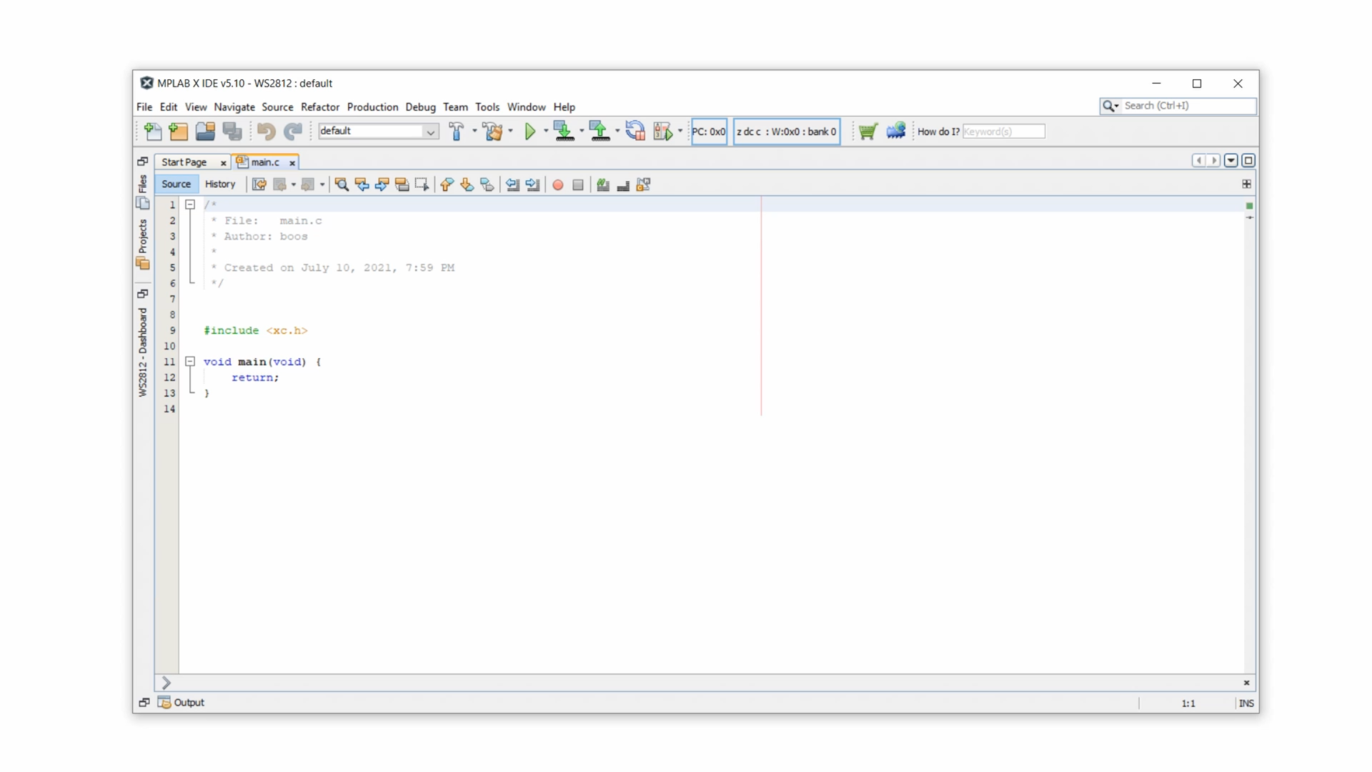
Then, for now, just delete everything you see in that window and just copy & paste the source code from below, and compile the code to a .hex-file, and flash that .hex-file onto the PIC16F1455. Then your breadboard should give you a little light show, something like that:
This part of the written tutorial is a bit short, I know, so if you want to see more details then I invite you to check out my WS2812 tutorial on YouTube :)
Software
But now let's talk a little bit about the software.
For PIC microcontrollers the instruction speed is one quarter of the clock speed, and we know that we need at least 400ns resolution for the WS2812 protocol. The PIC16F1455 can run at 48 MHz, which means 12 million instructions per second, or 83 nanoseconds per instruction. So let's take a look at this code:
DATA = 0; DATA = 1; DATA = 0;This creates a high signal that is approximately 83 nanoseconds in duration, and that is perfect because then a 400ns can be created like this:
DATA = 0; DATA = 1; NOP(); NOP(); NOP(); NOP(); DATA = 0;Here, NOP stands for “no operation.” So each NOP()-command just waits for one instruction cycle, which is 83ns, so all of this adds up to 400ns, give or take. And that is the main idea of how we can replicate the WS2812 protocol inside our program. To make our life simpler, I defined this macro here:
// macro to send the bit 'b' (can be either 0 or 1)
#define send(b) DATA=1; NOP(); NOP(); NOP(); DATA=b; NOP(); NOP(); NOP(); NOP(); DATA=0; NOP(); NOP(); NOP(); NOP();
Now it is very important that the controller runs at 48MHz. If you run the same program at 4MHz it won't work. But how can we check that we are really running at 48MHz, without an oscilloscope?
The idea is very simple! Remember the LED blink program, our first-ever program? We can use it here, too. We simply define the constant __XTAL_FREQ to take the value 48,000,000, and then the command __delay_ms(500); should result in a half-second pause. This is easy enough to check with a normal watch. To do this, simply replace the main()-loop with the following:
    // main loop
    while (1) {


        LED = 1;
		__delay_ms(500);
		LED = 0;
		__delay_ms(500);


    }
Flash this code onto the PIC16F1455, and the LED0 should blink once a second. You can measure how manu times it blinks in one minute, and divide that by 60 and get an even better estimate of the frequency, too :)
Truth be told, I did this step when I developed this tutorial because I could not manage to get the PIC16F1455 to run at 48MHz, only 24 MHz (I think) because I messed something up with the registers. But it's always good practice, with more involved components such as the WS2812 LEDs, to have a simple LED connected that allows you to do some debugging. I do this in almost all my microcontroller projects.
Assuming that we convinced ourselves that our code really runs at 48MHz, we can now look at the sendByte()-function. This is basically just the send() macro repeated eight times:
// send out a byte b in WS2812 protocol
void sendByte (unsigned char b) {

    if (b & 0b10000000) { send(1); } else { send(0); }
    if (b & 0b01000000) { send(1); } else { send(0); }
    if (b & 0b00100000) { send(1); } else { send(0); }
    if (b & 0b00010000) { send(1); } else { send(0); }
    if (b & 0b00001000) { send(1); } else { send(0); }
    if (b & 0b00000100) { send(1); } else { send(0); }
    if (b & 0b00000010) { send(1); } else { send(0); }
    if (b & 0b00000001) { send(1); } else { send(0); }

}
In each line, it checks all of the eight bits of the byte b, and if that bit is set it sends out a WS2812-encoded “1,” and if that bit is not set it sends out a WS2812-encoded “0.” We need to keep in mind that the if-else statement also takes some time to execute, and that is why in the first part of the send() macro there is one NOP() less than you might expect, which I figured out during some trial and error with my oscilloscope:
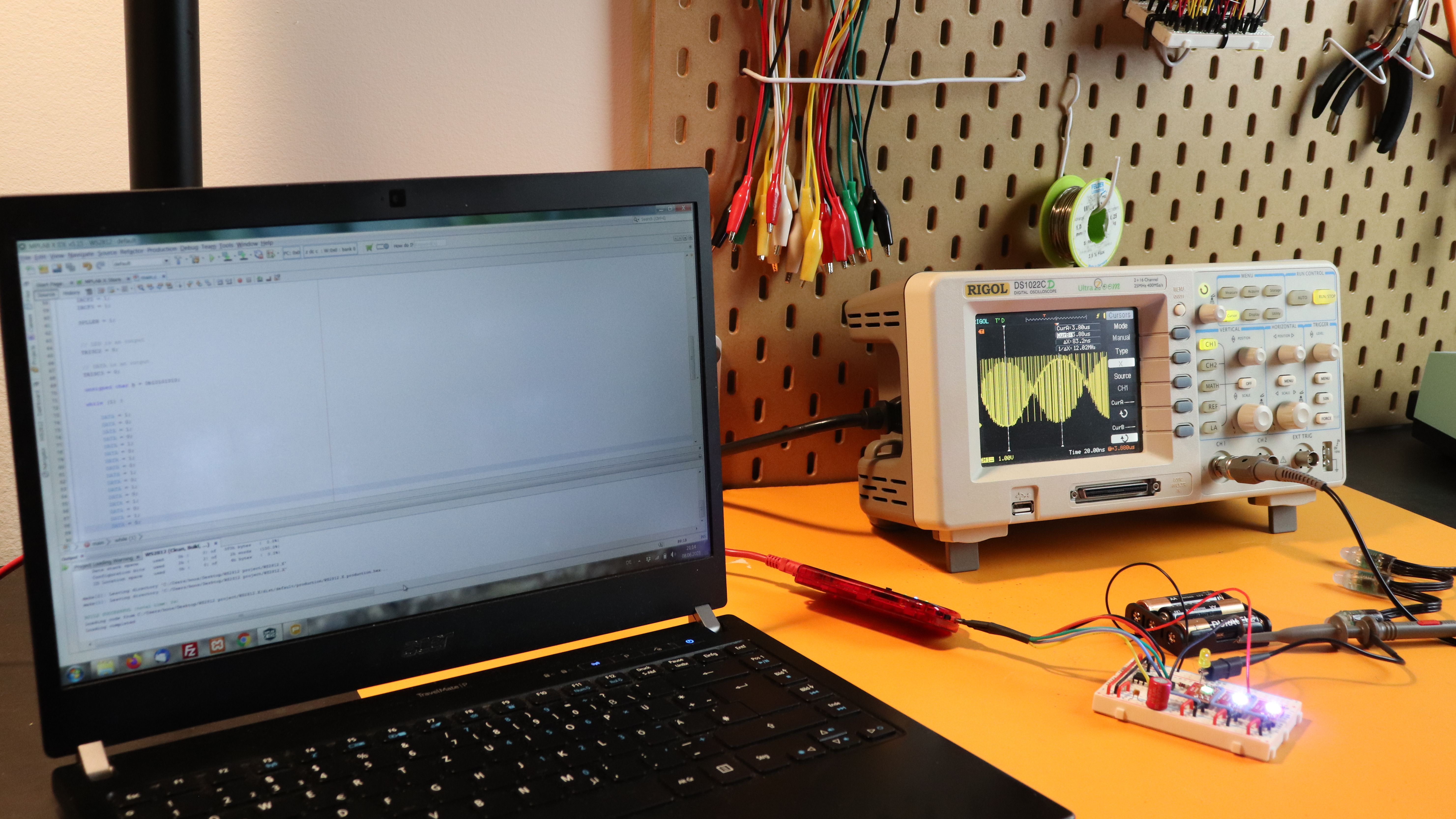
But hey, if you don't have an oscilloscope then don't worry about it, this code will get you started. And if it doesn't work, for some reason, try adding or removing single NOP() commands and see what happens :)
And now we can just combine three sendByte()-commands to send out any color we want:
// send red, green, and blue values in WS2812 protocol
void sendRGB (unsigned char r, unsigned char g, unsigned char b) {

    sendByte(g);
    sendByte(r);
    sendByte(b);

}
And that's it! The main()-loop of the program just runs through some animations, and that is honestly just a quick demo of what the LEDs can do, in your own applications this will of course be something different. For example, you could try to replicate the binary clock or the electronic dice:

YouTube video
I covered this entire tutorial in a dedicated YouTube video:
Final thoughts
I really like using the WS2812 LEDs, they are really quite useful. But as with many (or all) good things in life, there are a few important points to note:
- The WS2812 LEDs need a PIC running at a rather high speed of 48MHz (it may be possible to work at 24MHz too, but that would require some changes to the code). A lot of the older PICs cannot run at these high frequencies, so this is definitely a limitation that follows from the fast WS2812 timing protocol.
- I used the WS2812 as an RGB LED here, for simple purposes that are not very time-critical. You could also use the WS2812 LED as a pixel in a very large screen, and people actually have done that (see Bitluni's WS2812 LED wall for example). For these purposes our PIC16F1455 is certainly not powerful enough :)
- The WS2812 LEDs use pulse-width modulation (PWM) for adjusting the brightness of its red, green, and blue LED. The PWM frequency of the WS2812 is quite low at only 400Hz, which means that on some cameras it can create flickering effects when taking video.
- And last, some WS2812-type LEDs you find online have a slightly different protocol, in the sense that red and green are swapped around. For example, my WS2812 LED chain that I showed above in a photo has that issue. At first I didn't know what I was looking at, but simply swapping all red and green values in the code did the trick. So be mindful of that :)
Overall I am quite happy with these WS2812 LEDs, and I am sure that I will use them in some of my future project. But it is also nice to use regular LEDs once in a while, so I guess what I am really saying is: it's nice to have a choice!
As always, please reach out to me on social media if you have questions, comments, or if something doesn't work, I am sure we can figure it out! Thank you so much for reading, and I will see you next time! :)
Appendix: The full source code
Here you can find the full source code. The code (as well as the .hex file) are also available for download in the resources box.
/*
 * File:   main.c
 * Author: boos
 *
 * Created on May 16, 2021, 10:27 PM
 */

// CONFIG1
#pragma config FOSC = INTOSC    // Oscillator Selection Bits (INTOSC oscillator: I/O function on CLKIN pin)
#pragma config WDTE = OFF       // Watchdog Timer Enable (WDT disabled)
#pragma config PWRTE = OFF      // Power-up Timer Enable (PWRT disabled)
#pragma config MCLRE = OFF      // MCLR Pin Function Select (MCLR/VPP pin function is digital input)
#pragma config CP = OFF         // Flash Program Memory Code Protection (Program memory code protection is disabled)
#pragma config BOREN = OFF      // Brown-out Reset Enable (Brown-out Reset disabled)
#pragma config CLKOUTEN = OFF   // Clock Out Enable (CLKOUT function is disabled. I/O or oscillator function on the CLKOUT pin)
#pragma config IESO = OFF       // Internal/External Switchover Mode (Internal/External Switchover Mode is disabled)
#pragma config FCMEN = OFF      // Fail-Safe Clock Monitor Enable (Fail-Safe Clock Monitor is disabled)

// CONFIG2
#pragma config WRT = OFF        // Flash Memory Self-Write Protection (Write protection off)
#pragma config CPUDIV = NOCLKDIV// CPU System Clock Selection Bit (NO CPU system divide)
#pragma config USBLSCLK = 48MHz // USB Low Speed Clock Selection bit (System clock expects 48 MHz, FS/LS USB CLKENs divide-by is set to 8.)
#pragma config PLLMULT = 3x     // PLL Multipler Selection Bit (3x Output Frequency Selected)
#pragma config PLLEN = ENABLED  // PLL Enable Bit (3x or 4x PLL Enabled)
#pragma config STVREN = OFF     // Stack Overflow/Underflow Reset Enable (Stack Overflow or Underflow will not cause a Reset)
#pragma config BORV = LO        // Brown-out Reset Voltage Selection (Brown-out Reset Voltage (Vbor), low trip point selected.)
#pragma config LPBOR = OFF      // Low-Power Brown Out Reset (Low-Power BOR is disabled)
#pragma config LVP = OFF        // Low-Voltage Programming Enable (Low-voltage programming disabled)

#include <xc.h>


// location of the LED, DATA output, and pushbutton
#define LED RC2
#define DATA RC3
#define SW1 !RA5


// frequency is 48MHz
// (need this so that __delay_ms() works properly)
#define _XTAL_FREQ 48000000


// macro to send the bit 'b' (can be either 0 or 1)
#define send(b) DATA=1; NOP(); NOP(); NOP(); DATA=b; NOP(); NOP(); NOP(); NOP(); DATA=0; NOP(); NOP(); NOP(); NOP();


// auxiliary functions to control the WS2812 NeoPixel LEDs
void sendByte (unsigned char b);
void sendRGB (unsigned char r, unsigned char g, unsigned char b);


// main function
void main (void) {


    // set up internal oscillator to run at 48 MHz

    // set the SCS settings (system clock select)
    // to use the frequency specified in configuration word (line 9)
    SCS0 = 0;
    SCS1 = 0;

    // set to 16 MHz configuration
    IRCF0 = 1;
    IRCF1 = 1;
    IRCF2 = 1;
    IRCF3 = 1;

    // enable PLL to result in 48MHz
    // (PLL is set to 3x in line 23)
    SPLLEN = 1;


    // set up peripherals

    // LED is an output
    TRISC2 = 0;

    // DATA is an output
    TRISC3 = 0;

    // turn off analog to digital converter
    ANSC2 = 0;
    ANSC3 = 0;

    // button input
    TRISA5 = 1;
    WPUA5 = 1;
    nWPUEN = 0;


    // declare variables used for animation
    unsigned char brt = 1, dir = 1;
    int timebase = 0, stage = 0;


    // main loop
    while (1) {


        // react to button press
        if (SW1) {
            LED = 1;
            brt += dir;
            if (brt >= 255) {
                dir = -1;
            } else if (brt == 0) {
                dir = 1;
            }
        } else {
            LED = 0;
        }


        // time the animation
        timebase++;
        if (timebase > 300) {
            timebase = 0;
            stage += 1;
            if (stage >= 8) {
                stage = 0;
            }
        }


        // send out animation pattern
        if (stage == 0) {
            sendRGB(0,0,0); sendRGB(0,0,0); sendRGB(0,0,0);
            sendRGB(0,0,0); sendRGB(brt,0,0); sendRGB(0,brt,0);sendRGB(0,0,brt); sendRGB(brt,brt,0); sendRGB(brt,0,brt); sendRGB(0,brt,brt); sendRGB(brt,brt,brt);
        } else if (stage == 1) {
            sendRGB(brt,0,0); sendRGB(brt,0,0); sendRGB(brt,0,0);
            sendRGB(brt,brt,brt); sendRGB(0,0,0); sendRGB(brt,0,0); sendRGB(0,brt,0);sendRGB(0,0,brt); sendRGB(brt,brt,0); sendRGB(brt,0,brt); sendRGB(0,brt,brt);
        } else if (stage == 2) {
            sendRGB(0,brt,0); sendRGB(0,brt,0); sendRGB(0,brt,0);
            sendRGB(0,brt,brt); sendRGB(brt,brt,brt); sendRGB(0,0,0); sendRGB(brt,0,0); sendRGB(0,brt,0);sendRGB(0,0,brt); sendRGB(brt,brt,0); sendRGB(brt,0,brt);
        } else if (stage == 3) {
            sendRGB(0,0,brt); sendRGB(0,0,brt); sendRGB(0,0,brt);
            sendRGB(brt,0,brt); sendRGB(0,brt,brt); sendRGB(brt,brt,brt); sendRGB(0,0,0); sendRGB(brt,0,0); sendRGB(0,brt,0);sendRGB(0,0,brt); sendRGB(brt,brt,0);
        } else if (stage == 4) {
            sendRGB(brt,brt,0); sendRGB(brt,brt,0); sendRGB(brt,brt,0);
            sendRGB(brt,brt,0); sendRGB(brt,0,brt); sendRGB(0,brt,brt); sendRGB(brt,brt,brt); sendRGB(0,0,0); sendRGB(brt,0,0); sendRGB(0,brt,0); sendRGB(0,0,brt);
        } else if (stage == 5) {
            sendRGB(brt,0,brt); sendRGB(brt,0,brt); sendRGB(brt,0,brt);
            sendRGB(0,0,brt); sendRGB(brt,brt,0); sendRGB(brt,0,brt); sendRGB(0,brt,brt); sendRGB(brt,brt,brt); sendRGB(0,0,0); sendRGB(brt,0,0); sendRGB(0,brt,0);
        } else if (stage == 6) {
            sendRGB(0,brt,brt); sendRGB(0,brt,brt); sendRGB(0,brt,brt);
            sendRGB(0,brt,0); sendRGB(0,0,brt); sendRGB(brt,brt,0); sendRGB(brt,0,brt); sendRGB(0,brt,brt); sendRGB(brt,brt,brt); sendRGB(0,0,0); sendRGB(brt,0,0);
        } else if (stage == 7) {
            sendRGB(brt,brt,brt); sendRGB(brt,brt,brt); sendRGB(brt,brt,brt);
            sendRGB(brt,0,0); sendRGB(0,brt,0); sendRGB(0,0,brt); sendRGB(brt,brt,0); sendRGB(brt,0,brt); sendRGB(0,brt,brt); sendRGB(brt,brt,brt); sendRGB(0,0,0);
        }


        // wait some time
        __delay_ms(1);


    }

    return;

}

// send out a byte b in WS2812 protocol
void sendByte (unsigned char b) {

    if (b & 0b10000000) { send(1); } else { send(0); }
    if (b & 0b01000000) { send(1); } else { send(0); }
    if (b & 0b00100000) { send(1); } else { send(0); }
    if (b & 0b00010000) { send(1); } else { send(0); }
    if (b & 0b00001000) { send(1); } else { send(0); }
    if (b & 0b00000100) { send(1); } else { send(0); }
    if (b & 0b00000010) { send(1); } else { send(0); }
    if (b & 0b00000001) { send(1); } else { send(0); }

}

// send red, green, and blue values in WS2812 protocol
void sendRGB (unsigned char r, unsigned char g, unsigned char b) {

    sendByte(g);
    sendByte(r);
    sendByte(b);

}


