How to adjust LED brightness with a PIC microcontroller
August 2, 2019 • tutorial
In our first real microcontroller project we made an LED blink: it could be either ON or OFF. But what if you want to control the brightness of the LED and dim it? With a microcontroller this is usually accomplished by pulse width modulation, or PWM for short, and in this tutorial we will learn how to dim an LED using the PWM module inside a PIC16F627A microcontroller!
You already know the schematic!
Before we get deep into the topic of PWM, let me just mention one thing: you already know the schematic! This article uses exactly the same schematic and components as the blink LED tutorial. This is because we are using a microcontroller, and to change the behavior of what it does we do not always have to change the entire circuit, but we can rather change the software. Here is the schematic:
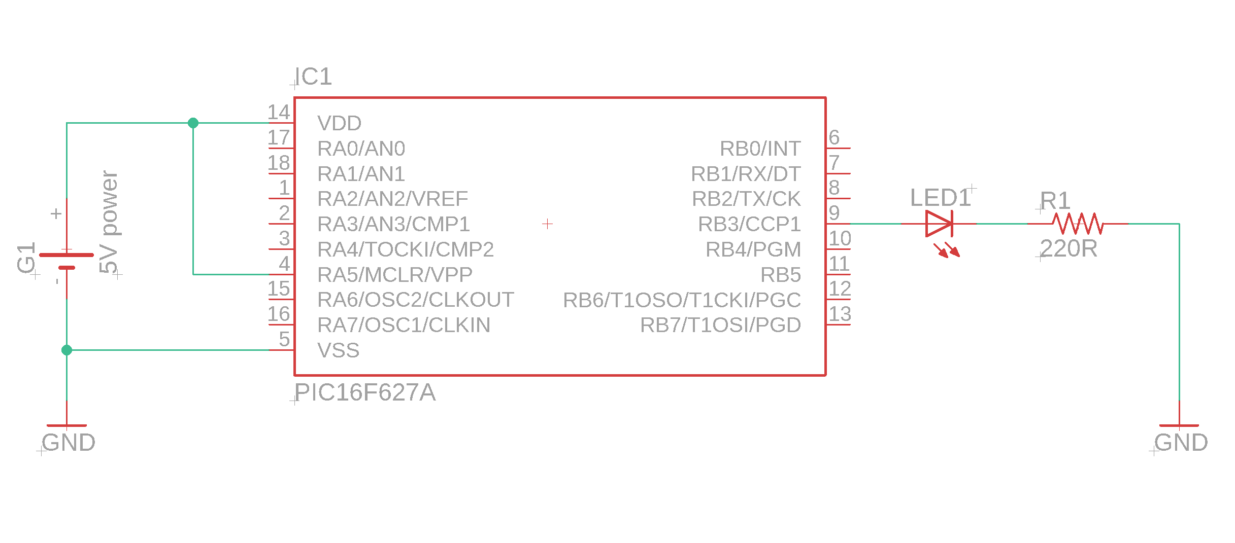
As you can see, it is very simple. There is one important detail: for the PIC16F627A, only the pin RB3 offers the PWM functionality. Other microcontrollers might have multiple PWM pins (or none at all), so it is always a good idea to check out your favorite controller's datasheet. You can find the datasheet for the PIC16F627A in the resources box of this article.
Alright, with that out of the way, let's get started!
What is pulse width modulation (PWM)?
The idea of PWM is to use a digital output pin that can only be ON or OFF and create the illusion of it being only half-way ON (or a third, or 10%, or anything you want). In simple terms: microcontrollers have digital output pins. They can either be HIGH or LOW (or, in normal language, ON or OFF).
If you run your microcontroller on +5V (which we usually do around here), then the output can be +5V or 0V. If you connect an LED to that pin, the LED is either ON or OFF.
So how do we dim the LED's brightness? A simple way, if we only want half the brightness, to only connect 2.5V instead of 5V. Then the LED should be at half its brightness. The problem: a microcontroller output pin cannot supply 2.5V. But there is a loophole!
If we want half the brightness, we can instead make the average voltage to be 2.5V! How does that work? By switching the LED on and off really quickly. And if we switch it on and off quickly enough, the human eye won't register the flickering at all!
Let's explain it in a few diagrams. On the x-axis you have the time, and on the y-axis you have the voltage. If the LED is permanently ON, it looks like this:
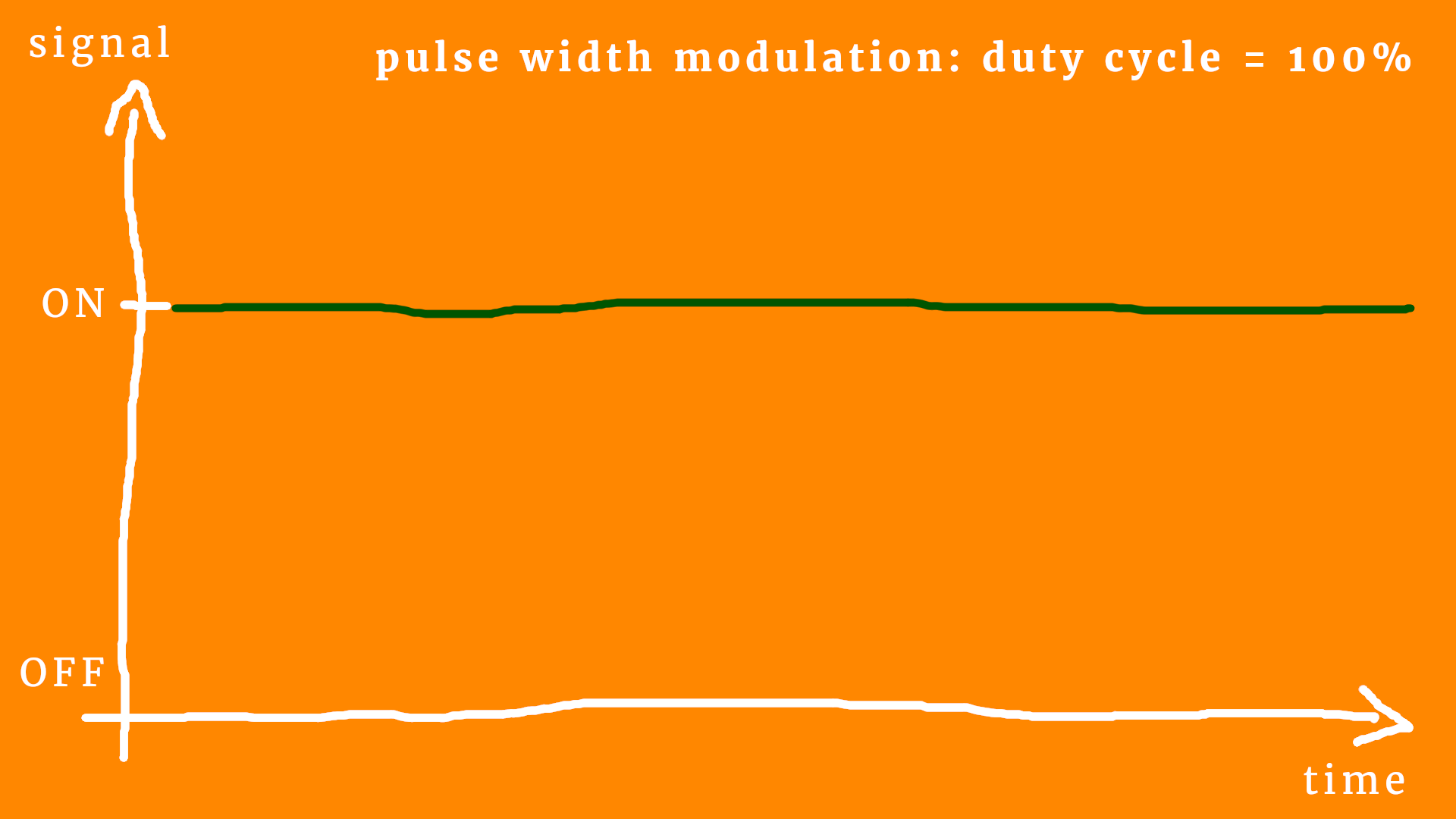
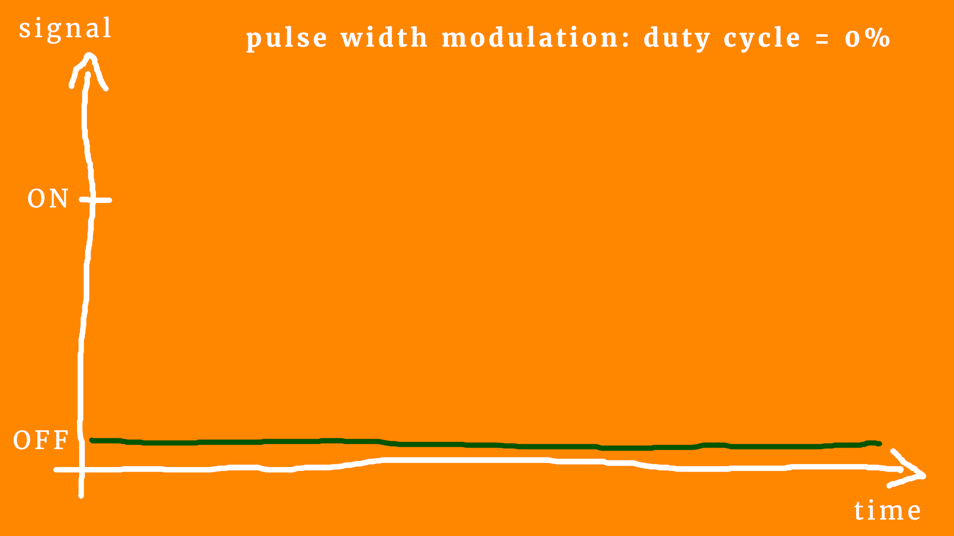
OK, that's boring :) But we can learn some new language! If the LED is on all the time, we say that the duty cycle is 100%. And, conversely, if the LED is off all the time, the duty cycle is 0%, like this:
But I hope you get the idea: to reduce the LED's brightness, we simply go for a duty cycle value between 100% (completely on) and 0% (completely off). Like this:
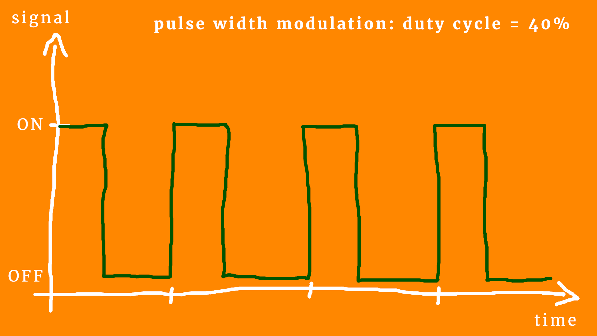
This corresponds to a duty cycle of around 40%. Let's add some details so that we can talk about it in more accurate technical terms :) Here is the same diagram again:
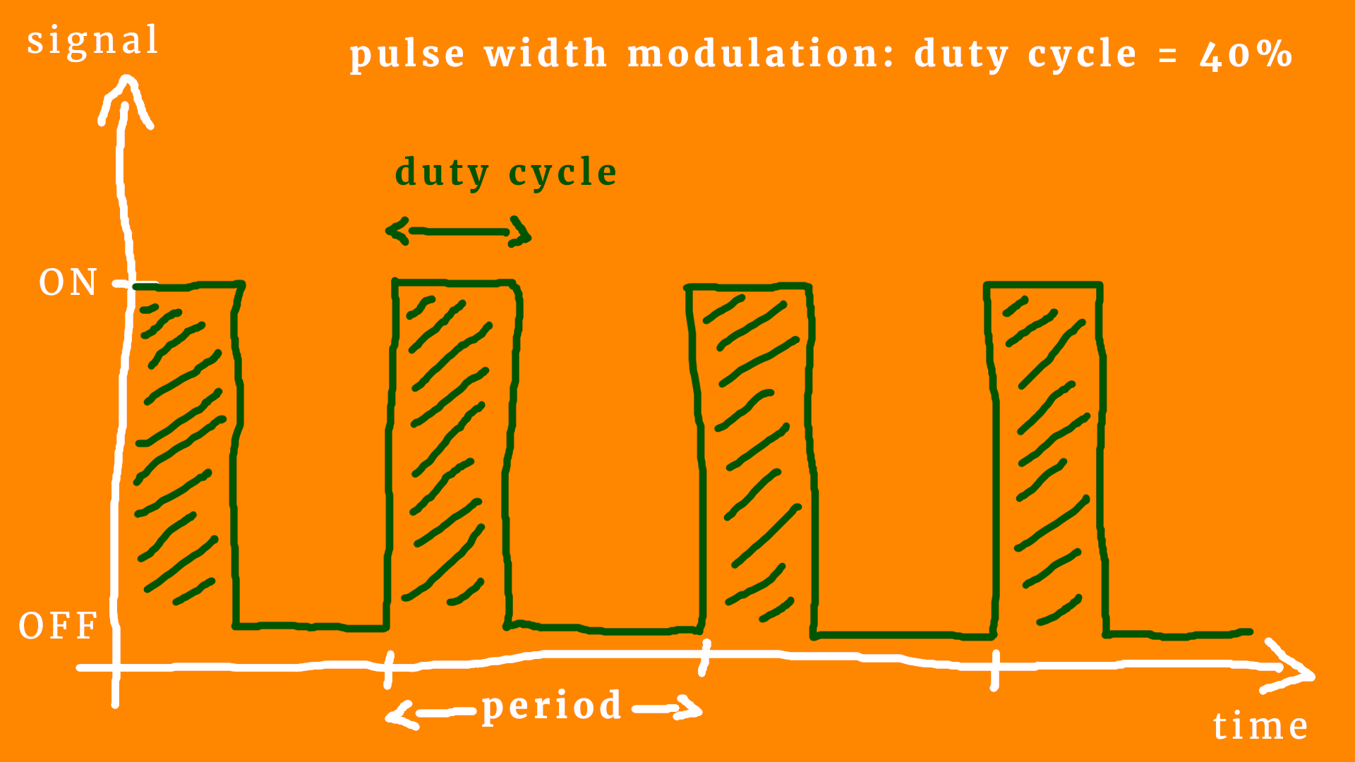
Let's go through the diagram systematically, step by step :)
- You can see the PWM is periodic. It happens over and over and over again, it is a continuous process. The duration of one full cycle is called the period, and it is measured in seconds (or, typically, in milliseconds or even microseconds, because it has to be fast).
- The inverse of the PWM period is the PWM frequency. For example, if the period is 10 milliseconds, then it corresponds to 100 cycles a second, which in term means 100 Hertz (or Hz for short). The PWM frequency is usually fixed, meaning that when you design a PWM circuit you think about what kind of PWM frequency you need, and then you run with it.
- The duty cycle (sometimes abbreviated as DC) is the ratio of ON-time and period. In other words, it is the amount of time the LED is ON per period. It is usually given as a percentage between 0% (always off) and 100% (always on).
- I added some squiggly lines whenever the signal is ON to make it a bit easier to see. The human eye is slow. This is sometimes called persistence of vision: when we watch a movie we see it as a fluent motion, right? But in reality it is pictures that are shown in rapid succession! In the same way we think that the LED is a bit dimmer when it is rapidly switched on and off.
And now we can understand the name “pulse width modulation!” The more the LED is on (the higher the duty cycle), the brighter it appears. And the lover the duty cycle is, the dimmer it appears. Makes sense? So, in order to dim the LED, we modulate the pulse width. And pulse width is just another name for duty cycle. (Technically, the pulse width is the duty cycle multiplied with the period, so that it has the unit of time.)
There is one last technical detail, and that is the so-called PWM resolution.
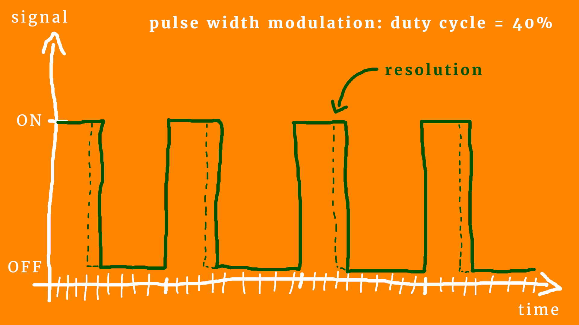
What does it mean? Well, we want to achieve PWM with a microcontroller, and they work with a certain frequency (as we learned in the article What makes a microcontroller tick?). This means that they can be fast, even very fast, but they do not have an infinite time resolution.
This means: once we fix the PWM frequency to 20kHz or so, we cannot have an arbitrarily fine resolution in the duty cycle. This is what the tiny white additional marks are supposed to indicate: the minimal time resolution.
In other words: we can only vary the duty cycle in discrete steps.
But wait, some of you might say, can't we just make the period bigger? Then the resolution will be finer! This is true! Yes! But we also cannot make the period arbitrarily big!
Think about it this way. The time resolution is always fixed, say it is one microsecond (one millionth of a second) and the period is 1ms. Then your resolution is 0.1%, because 1 microsecond divided my one millisecond is 1/1000, which is 0.1% expressed in percents. If you now choose a period of one second insterad, the resolution would be come a thousand times greater! Wow! Where's the catch? At a period of one second, the persistence of vision stops working, and we will see the LED blink.
Here is this idea summarized in a magic triangle:

This triangle is supposed to show the basic dilemma that you will encounter when designing a PWM circuit:
- If you want a super high resolution, you will either need a ridiculously high PWM frequency or your display will start to flicker.
- If you don't want your display to flicker, you need either a low resolution or a large PWM frequency.
- If you don't want to use a large PWM frequency (which is not always possible, because most microcontrollers have a fixed maximum frequency) you will need to either compromise on resolution or you will have some flickering.
But the good news is: there is a sweet spot for almost any application! We will discuss below what kind of parameters work really well for LEDs :)
How do we control the PWM module?
Okay, now that we understand the basics, let's use our LED blink breadboard and adjust the LED's brightness! Luckily for us, the PIC16F627A has a PWM module built-in. In the appendix you can find the full source code for this project, but let us go through the basics together right now! (As always, you can find the readily compiled hex file in the resources box of this article.)
The program is mostly identical to that of the blink LED, which is why I will only describe the parts that are relevant for the PWM stuff. Let's go!
Our LED is connected to pin RB3. In the datasheet (see resources box) this pin is also called CCP1:
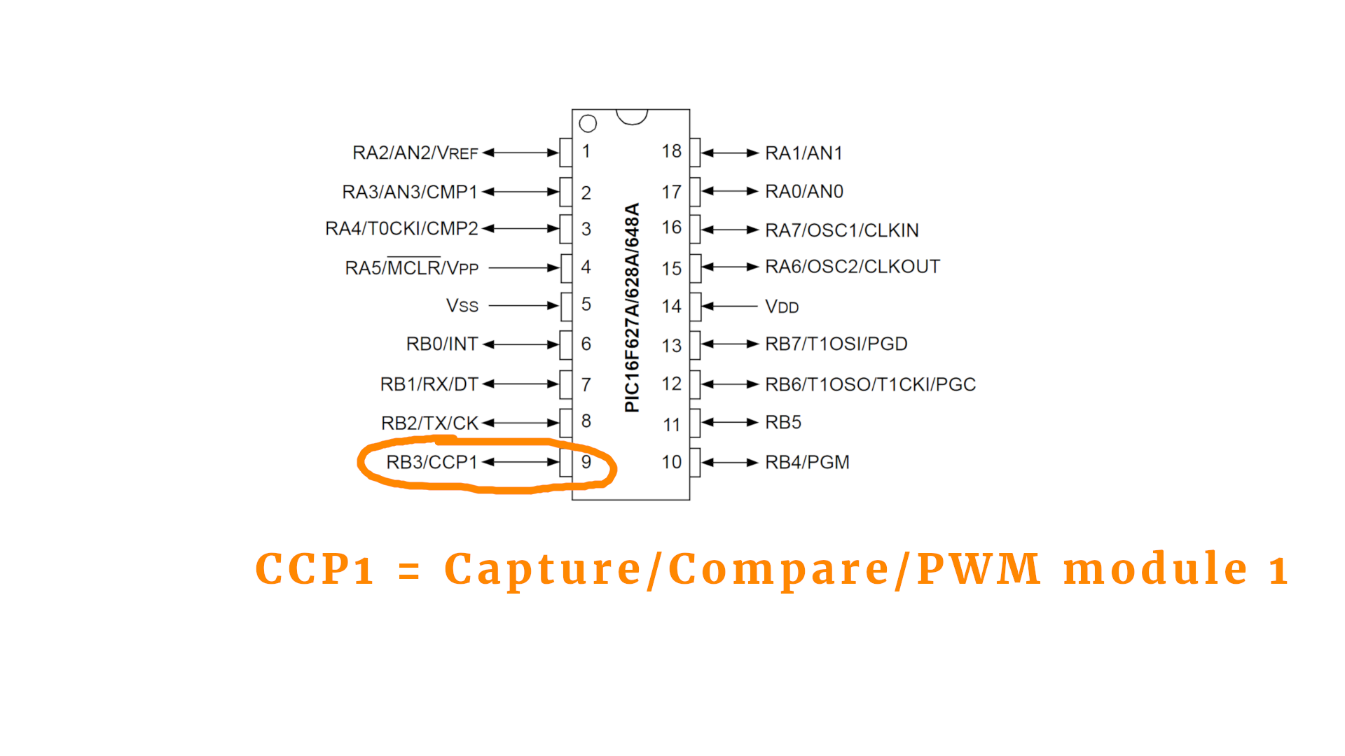
The abbreviation CCP1 has nothing to do with the Soviet Union but rather stands for Capture/Compare/PWM module 1. Other controllers have more of these modules, which is why they are typically numbered (even, as in this case, when there is only one of them). You can read more about it in the datasheet in Section 9, page 55.
The CCP1 module does more than just PWM, so we have to activate the PWM mode somehow. We will do that below in all detail :) But first, we have to tell the controller that we will connect an LED to it at port RB3, and we do that as follows:
// PORT RB3 is an output
TRISB3 = 0;
As usual, the line numbers in this and all other code snippets refer to the corresponding lines in the full program you can find in the appendix. Next, we need to select the PWM module by setting the CCP1CON register. It is just one simple line:
// start PWM module
CCP1CON = 0b1100;
Now we are in business, and the PWM module is turned ON. The PIC16F627A PWM module has a maximum resolution of 10 bit, which means it knows 1024 different steps (from 0 to 1023). The minimal resolution is 2 bit. Technically, we control the resolution by setting the upper limit of TIMER2. This way we set it to 10 bit (0xff means 255 in hexadecimal):
// set upper limit of TIMER2 (sets the PWM resolution)
PR2 = 0xff;
If we only wanted 8 bit resolution, we would set it to 64 instead. Together with the 2 bits of minimal resolution we would then obtain a full 8-bit.
Next we need to set the PWM frequency. Remembering the PWM magic triangle from above, we can now adjust the PWM frequency. The datasheet gives us the following formula:
PWM frequency = Fosc/(1024 × prescaler TIMER2)
OK, what does that mean?
- Fosc is the oscillator frequency, in this case this corresponds to the 4MHz of the internal oscillator. It is the speed the PIC controller runs with. The factor 1024 shows up because the PWM module has the resolution of 10 bit, which corresponds to 1024.
- The PWM frequency we already explained above. For an LED it is a good idea to have it in the kilohertz regime, so that there are a couple of thousand cycles per second. This way there will be no flickering. This means that we have to set the PWM frequency to, say, a few kHz.
- But what does prescaler TIMER2 stand for? It is a parameter that we need to set. The PWM module needs a counter to keep track of where in the cycle it is. Makes sense, right? It needs to know how much time has passed in each cycle, so that it can determine when to switch the output ON or OFF. We can cover the details of microcontroller timers in a later tutorial if you want, just let me know :)
The prescaler of TIMER2 can take the values 1, 4, or 16. Let us say we make it 1. Then, we can calculate the PWM frequency, and it will be around 4kHz. (Because 4MHz/1024/1 is roughly 4kHz.) This is great! If we set the prescaler instead to 4 or 16 the PWM frequency would go down to 1kHz or even 250Hz. Way too low, and we would see a flickering!
Long story short, the following lines set the prescaler to 1:
// set the prescaler of TIMER2 to 1:1 (bits no. 0 and 1)
// (00 = 1:1, 01 = 1:4, 1x = 1:16)
// and activate TIMER2 (bit no. 2)
T2CON = 0b100;
Then it is convenient to define a variable that contains the duty cycle value that we want the LED to follow:
// our duty cycle value
int DC = 0;
This is basically the brightness variable of our LED! But how do we tell the PWM module to apply a certain value to the LED brightness? Like this:
// set the 10-bit duty cycle value
CCPR1L = DC >> 2;
CCP1X = DC & 1;
CCP1Y = (DC >> 1) & 1;
It is a little cumbersome. Why? Because the resolution is 10-bit, on an 8-bit controller! This means that we cannot write a number larger than 255 in any one place. Therefore we have to split the number and the above lines do just that. This is a little bit technical and not too important for us right now (but you can read more about it here).
But that's it! That's all we need to know :) The main-loop of our program looks like this:
while (1) {

    // set the 10-bit duty cycle value
    CCPR1L = DC >> 2;
    CCP1X = DC & 1;
    CCP1Y = (DC >> 1) & 1;

    // increase the brightness by one
    DC += 1;
    if (DC >= 1024) {
        DC = 0;
    }

    // wait a bit
    __delay_ms(1);

}
All it does is increase the LED brightness in line 49, and set it back to zero if the maximum brightness is reached. After that we update the duty cycle value (lines 43-46) and then wait one millisecond (line 55). The delay is just put in there so that the LED does not change the brightness too quickly.
Final thoughts?
If you want to build this circuit to test it out, you can follow the instructions in the blink LED tutorial. Just remember to use instead the hex file of this project right here, which you can either compile yourself or download from the resources box and then flash onto the controller.
There is a detailed description of the PWM module in the PIC16F627A datasheet in Section 9, starting on page 55. It might be a bit technical, but don't be afraid. It is written in plain English, and you would be surprised by how much you can surely already understand!
I know that microcontrollers can be a bit intimidating, especially when you are new to the field. But you can understand it! If you are really stuck and don't know what is what, get in touch on social media and we will figure it out together :)
It is always a good idea, I think, to split a complicated problem (“I want to learn microcontrollers!”) into smaller ones (“How do I dim an LED?”). I hope this tutorial helps you on your journey through the fascinating world of microcontrollers! Thanks for reading!
Appendix: The full source code
Here you can find the full source code. The code (as well as the .hex file) are also available for download in the resources box.
/*
 * File:   main.c
 * Author: boos
 *
 * Created on July 31, 2019, 11:22 PM
 */

// CONFIG
#pragma config FOSC = INTOSCCLK // Oscillator Selection bits (INTOSC oscillator: CLKOUT function on RA6/OSC2/CLKOUT pin, I/O function on RA7/OSC1/CLKIN)
#pragma config WDTE = ON        // Watchdog Timer Enable bit (WDT enabled)
#pragma config PWRTE = OFF      // Power-up Timer Enable bit (PWRT disabled)
#pragma config MCLRE = ON       // RA5/MCLR/VPP Pin Function Select bit (RA5/MCLR/VPP pin function is MCLR)
#pragma config BOREN = ON       // Brown-out Detect Enable bit (BOD enabled)
#pragma config LVP = ON         // Low-Voltage Programming Enable bit (RB4/PGM pin has PGM function, low-voltage programming enabled)
#pragma config CPD = OFF        // Data EE Memory Code Protection bit (Data memory code protection off)
#pragma config CP = OFF         // Flash Program Memory Code Protection bit (Code protection off)

#include <xc.h>

#define _XTAL_FREQ 4000000

void main(void) {

    // PORT RB3 is an output
    TRISB3 = 0;

    // start PWM module
    CCP1CON = 0b1100;

    // set upper limit of TIMER2 (sets the PWM frequency)
    PR2 = 0xff;

    // set the prescaler of TIMER2 to 1:1 (bits no. 0 and 1)
    // (00 = 1:1, 01 = 1:4, 1x = 1:16)
    // and activate TIMER2 (bit no. 2)
    T2CON = 0b100;

    // our duty cycle value
    int DC = 0;

    while (1) {

        // set the 10-bit duty cycle value
        CCPR1L = DC >> 2;
        CCP1X = DC & 1;
        CCP1Y = (DC >> 1) & 1;

        // increase the brightness by one
        DC += 1;
        if (DC >= 1024) {
            DC = 0;
        }

        // wait a bit
        __delay_ms(1);

    }

    return;

}


