How to build a binary clock
July 29, 2019 • project
In the last weeks we have learned how to program PIC microcontrollers, how to connect pushbuttons, and how to create a 1Hz time base signal. Now it is time to put it all together and build a clock. But not just any clock, a binary clock! Binary is the number system used by computers, and it is ideally suited to display numbers by using simple LEDs! Let's do it!
Overview: the binary clock
Before we jump into the binary madness, I want to mention a couple of things. This project is more involved than any other we worked on before. So it is a good idea to have a look at the electronic dice project and the 1Hz article, because these build the foundation of the binary clock:
And, addressing the elephant in the room: how do we read binary? It is a number format that is used by computers and it consists solely of the numbers 0 and 1.
Here you can see the scheme of how to read the binary clock:
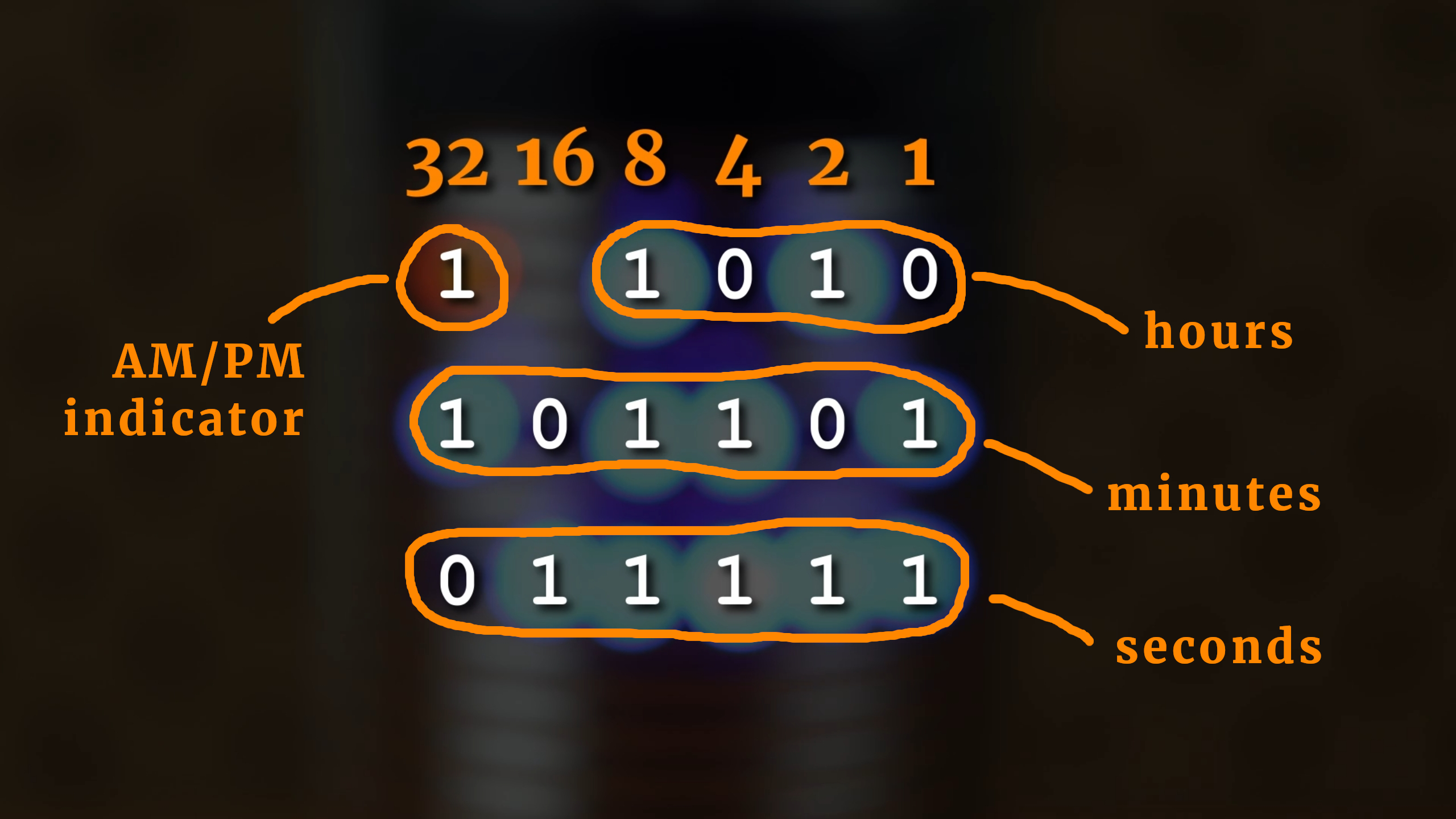
Take, for example, the hours. The binary number is 1010, which corresponds to 0x1 + 1x2 + 0x4 + 1x8, which is just equal to ten. The minutes read 101101, which amounts to 1x1 + 0x2 + 1x4 + 1x8 + 0x16 + 1x32, which adds up to 45. And the seconds? Well, 011111 is equal to 1x1 + 1x2 + 1x4 + 1x8 + 1x16 which is again equal to 31. We see: the time displayed is 10:45:31.
What do you need?
There are quite a few components needed for this project, most of them you can see in this picture:
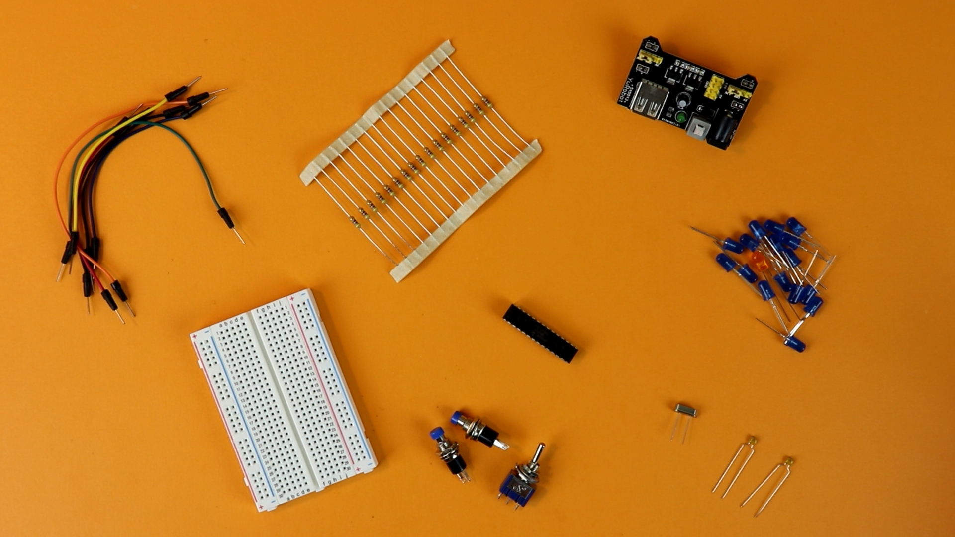
You can find a detailed list of everything that is required in the components box and a list of tools and auxiliary equipment in the tools box.
For some components I added two links as a possible resource. This has the following reason: some components (like LEDs, resistors, capacitors) are needed not just in this project but in many others as well. So it might make sense to consider buying a kit that contains many of these components in a set.
Some other components, for example the controller PIC16F883 (more on that below) are rather special items, and you cannot find them in kits. Rather, you should get them from an electronics distributor directly. See also my article Where to buy electronic components? for some ideas on that kind of question.
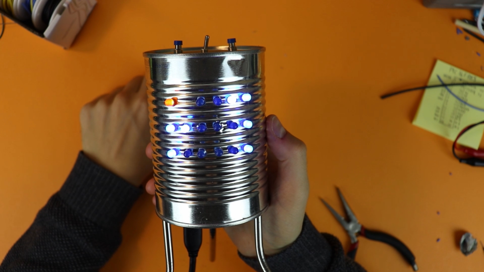
Last, I wanted to mention that this article describes how to build a binary clock exactly as you see it in the picture above. You certainly don't have to build it exactly this way. For example, you can make your own enclosure and not use a tin can. Or you can not connect the seconds and only have it display hours and minutes.
Okay, with that out of the way, let's get started!
The schematic
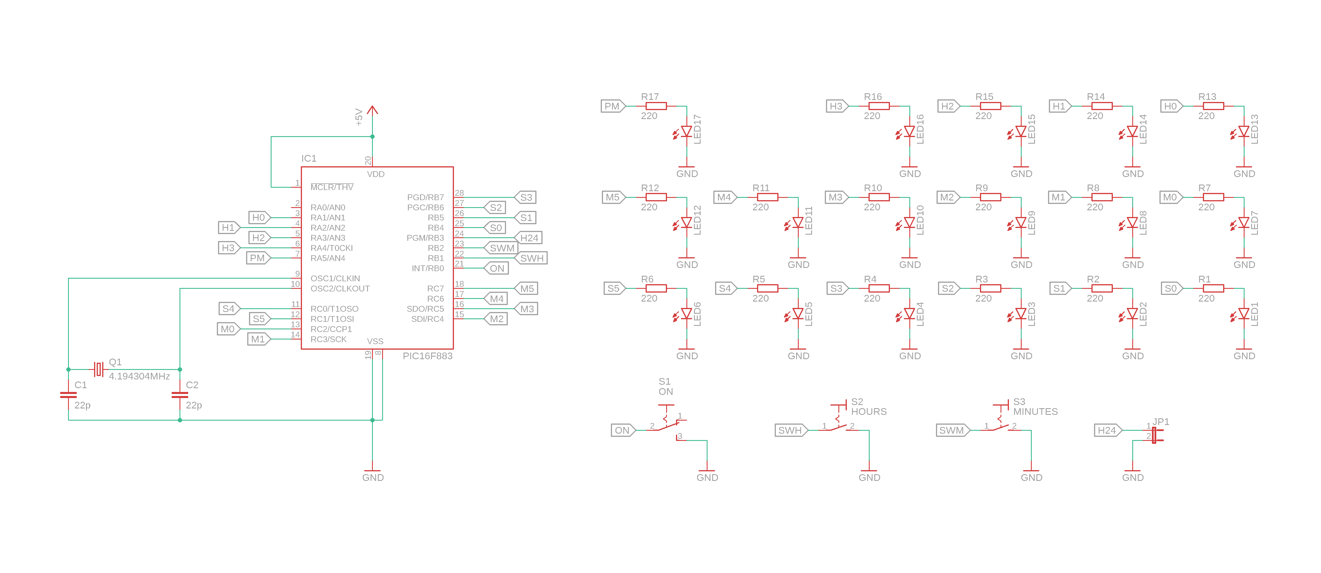
The schematic might scare you at first sight because it is seemingly more involved than that of the, say, electronic dice. But let's break it down into several parts.
- The main part is the microcontroller PIC16F883. This is a microcontroller just like our more familiar PIC16F627A, with the difference that it has slightly more pins. This is because we want to connect 17 LEDs and a few buttons, and the PIC16F627A simply does not have enough pins. OK.
- The PIC16F883 is connected to VDD (+5V), VSS (ground), and MCLR (Master Clear) exactly as we know it from the PIC16F627A. The only difference is that the PIC16F883 has two ground connections and not just one.
- On the left side we can see a 4.194304MHz crystal, which we already talked about in our article on crystals and our 1Hz timebase tutorial. We need an external oscillator in this project because the internal one (which is at around 4MHz) is not accurate enough to give us a stable 1Hz signal.
- On the right side you can see the 17 LEDs. I arranged them in the same way that they are mounted in the final binary clock. All LED cathodes (negative terminals) are permanently connected to ground. Their positive terminals (anodes) are connected to a 220 Ohms resistor. This resistor is then connected to the output of the PIC16F883.
- But why is there no connections visible from the LEDs to the controller? This is because I use labels. I explained the reason for that in a recent article on how to read schematics without being overwhelmed, but the basic idea is very simple: I use labels to keep the schematic clean and easy to read. When you are building this circuit then you have to connect all LEDs to the controller, of course. Take LED S0, for example. Its label is called S0, and you can find a corresponding label S0 at the PIC16F883 as well. Everything with the same label has to be connected to each other.
- There are also two pushbuttons and one toggle switch that have to be connected to the controller. They are used to set the time and to turn the LEDs on or off. They are connected directly to the controller without any external devices, and you can read more about that sort of thing in my article on how to read out a pushbutton with a PIC microcontroller.
- Last, you can decide whether the clock should work in AM/PM mode or in the 24 hour mode. If you like the 24 hour mode more, connect pin H24 to ground. This is what the symbol JP1 means, it is a jumper.
I know that I did not explain everything here. The reason is that I wrote many dedicated articles for these topics, as you can see by the crazy amount of links in the above list. I hope I can convince you that this is not laziness on my part.
Rather, I am a strong believer in subdividing even the most complicated problem into smaller bits. Then you can understand it! By going one step at a time :)
If you don't understand something here, please let me know on social media and I will do my best to get in touch and update the article so that it is easier to understand!
Programming the PIC16F883
Now that we understand the schematic, we need to know how to tell the microcontroller to actually “be” a clock. In other words: we need to write a program. You can find the complete program in the appendix at the bottom of the page, and you can download the source file in the resources box as well.
Here, we will go through the main parts of the code and explain what it does. The line numbers refer to the lines in the full source code in the appendix.
// CONFIG1
#pragma config FOSC = XT        // Oscillator Selection bits (XT oscillator: Crystal/resonator on RA6/OSC2/CLKOUT and RA7/OSC1/CLKIN)
#pragma config WDTE = OFF       // Watchdog Timer Enable bit (WDT disabled and can be enabled by SWDTEN bit of the WDTCON register)
#pragma config PWRTE = OFF      // Power-up Timer Enable bit (PWRT disabled)
#pragma config MCLRE = ON       // RE3/MCLR pin function select bit (RE3/MCLR pin function is MCLR)
#pragma config CP = OFF         // Code Protection bit (Program memory code protection is disabled)
#pragma config CPD = OFF        // Data Code Protection bit (Data memory code protection is disabled)
#pragma config BOREN = ON       // Brown Out Reset Selection bits (BOR enabled)
#pragma config IESO = OFF       // Internal External Switchover bit (Internal/External Switchover mode is disabled)
#pragma config FCMEN = OFF      // Fail-Safe Clock Monitor Enabled bit (Fail-Safe Clock Monitor is disabled)
#pragma config LVP = OFF        // Low Voltage Programming Enable bit (low voltage programming disabled)

// CONFIG2
#pragma config BOR4V = BOR40V   // Brown-out Reset Selection bit (Brown-out Reset set to 4.0V)
#pragma config WRT = OFF        // Flash Program Memory Self Write Enable bits (Write protection off)
Only line 9 is important, the rest is standard initialization stuff. Line 9 tells the controller NOT to use its internal oscillator, but to use an external crystal at pints RA6 and RA7.
// define names

#define ONOFF RB0
#define SWH RB1
#define SWM RB2
#define H24 RB3

#define S0  RB4
#define S1  RB5
#define S2  RB6
#define S3  RB7
#define S4  RC0
#define S5  RC1

#define M0  RC2
#define M1  RC3
#define M2  RC4
#define M3  RC5
#define M4  RC6
#define M5  RC7

#define H0  RA1
#define H1  RA2
#define H2  RA3
#define H3  RA4
#define PM  RA5
This part is strictly speaking not necessary, but I like it. I define names for the different pins of the PIC16F883 so that the rest of the code is more readable. What makes more sense? Referring to a pin as RB3 or calling it instead H24 so you know it is the pin that decides whether we are in 24 hour mode or not? I hope you get the idea :)
// these variables store the time
unsigned char seconds = 0, minutes = 0, hours = 0, hours12 = 0;

// time buffer
int TIME_BUFFER = 0;

// switch debounce buffers
int SWH_BUFFER = 0;
int SWM_BUFFER = 0;
In these lines we define our variables. The variables seconds, minutes and hours store the time. The variable hour12 contains the hour information in 12 hour format. The variable TIME_BUFFER is probably the most important one. It is used to create the 1Hz clock that makes our binary clock tick. More on that below :)
The variables SWH_BUFFER and SWM_BUFFER are used to debounce the pushbuttons.
// the main function
void main (void) {

    // enable weak pull-up resistors on PORTB
    nRBPU = 0;
We have reached the main function! Line 67 turns on the weak internal pull-up resistors on PORTB, and I explain this in my article here. In short: it allows us to connect our buttons to PORTB without the need of external resistors, so it is quite convenient.
    // switch OFF the analog to digital converter (ADC)
    // because we do not need it here
    ADON = 0;
    ANS0 = 0;
    ANS1 = 0;
    ANS2 = 0;
    ANS3 = 0;
    ANS4 = 0;
    ANS8 = 0;
    ANS9 = 0;
    ANS10 = 0;
    ANS11 = 0;
    ANS12 = 0;
    ANS13 = 0;
The PIC16F883 is a rather complex controller with a lot of built-in functionality. But we don't need all of that stuff. The above lines switch off the so-called analog to digital converter (ADC) so that we can use all pins as regular inputs or outputs. You can read more about that in the PIC16F883 datasheet if you want.
    // these pins are inputs
    TRISB0 = 1;
    TRISB1 = 1;
    TRISB2 = 1;
    TRISB3 = 1;

    // and all of these pins are outputs
    TRISB4 = 0;
    TRISB5 = 0;
    TRISB6 = 0;
    TRISB7 = 0;
    TRISC0 = 0;
    TRISC1 = 0;
    TRISC2 = 0;
    TRISC3 = 0;
    TRISC4 = 0;
    TRISC5 = 0;
    TRISC6 = 0;
    TRISC7 = 0;
    TRISA1 = 0;
    TRISA2 = 0;
    TRISA3 = 0;
    TRISA4 = 0;
    TRISA5 = 0;
In the lines above we tell the PIC16F883 which pins are to be configured as inputs and which ones are outputs. We can do that by setting the so-called TRISTATE registers. If a TRISTATE register is set to 1, the corresponding pin is an input (easy to remember because a 1 looks like the letter I), and if the TRISTATE register is set to 0, the pin becomes an output (and, yes, a 0 looks like the letter O).
    // initialize TIMER0

    // TIMER0 works with 1/4 of the internal clock
    // (that amounts to 1.048576 MHz)
	T0CS = 0;

	// set the TIMER0 prescaler to 1:1
	PSA = 1;
	PS0 = 1;
	PS1 = 1;
	PS2 = 1;

	// create an interrupt when TIMER0 overflows
	T0IE = 1;

    // enable interrupts
	GIE = 1;
These lines are among the most important ones in this entire program. They tell the controller, roughly speaking, to call a special function (see below) 4096 times a second. This topic involves interrupts and I explained it previously in my 1Hz article here.
// the main loop
    while (1) {

        // only show the time if the toggle
        // switch is turned to the ON position
        if (!ONOFF) {

            // show seconds
            S0 = (seconds & 0b000001) >> 0;
            S1 = (seconds & 0b000010) >> 1;
            S2 = (seconds & 0b000100) >> 2;
            S3 = (seconds & 0b001000) >> 3;
            S4 = (seconds & 0b010000) >> 4;
            S5 = (seconds & 0b100000) >> 5;

            // show minutes
            M0 = (minutes & 0b000001) >> 0;
            M1 = (minutes & 0b000010) >> 1;
            M2 = (minutes & 0b000100) >> 2;
            M3 = (minutes & 0b001000) >> 3;
            M4 = (minutes & 0b010000) >> 4;
            M5 = (minutes & 0b100000) >> 5;
We have reached the main loop that gets executed over and over again, as long as the clock is turned on.
In line 132 we check if the LED toggle switch is set to the ON position. If so, we calculate the value of each LED and turn it off or on.
These cryptic looking expressions like (minutes & 0b000100) >> 3 are very easy to understand: they simply check if a certain bit is set or not. The code in line 146 that I just quoted, for example, checks if there is a 4 in the minutes or not. If yes, it turns the LED M3 on, otherwise it doesn't.
Another way of looking at it: these lines translate the time information that is stored in our time variables into the binary code that is displayed by the LEDs.
These operations are also called Boolean operations, and if you want to learn more about it, let me know! :)
// show hours in AM/PM format
            if (H24) {

                // convert to 12 hour display
                hours12 = hours;
                if (hours > 12) {
                    hours12 -= 12;
                } else if (hours == 0) {
                    hours12 = 12;
                }
                H0 = (hours12 & 0b000001) >> 0;
                H1 = (hours12 & 0b000010) >> 1;
                H2 = (hours12 & 0b000100) >> 2;
                H3 = (hours12 & 0b001000) >> 3;

                // PM indicator
                if (hours > 11) {
                    PM = 1;
                } else {
                    PM = 0;
                }

            // show hours in 24 hour format
            } else {

                H0 = (hours & 0b000001) >> 0;
                H1 = (hours & 0b000010) >> 1;
                H2 = (hours & 0b000100) >> 2;
                H3 = (hours & 0b001000) >> 3;
                PM = (hours & 0b010000) >> 4;

            }
Because our clock can run in AM/PM mode or in 24 hour mode, the hours are treated separately. If the AM/PM mode is active (line 151) we need to calculate the hours in the 12 hour format from the hours in the 24 hour format first. Otherwise, see line 173, we just display everything as-is.
            // adjust hours?
            if ((!SWH) && (SWH_BUFFER == 0)) {
                SWH_BUFFER = 1000;
                hours++;
                if (hours >= 24) {
                    hours = 0;
                }
                seconds = 0;
            }

            // adjust minutes?
            if ((!SWM) && (SWM_BUFFER == 0)) {
                SWM_BUFFER = 1000;
                minutes++;
                if (minutes >= 60) {
                    minutes = 0;
                }
                seconds = 0;
            }
In these lines we react to the pushbutton. If it is pressed, we increase the hours or minutes accordingly. This part is only executed if the main LED toggle switch is set to ON. This guarantees that we cannot change the time by pressing the buttons when the LEDs are turned off. I think this makes the binary clock more user friendly.
// switch all LEDs off if the toggle switch
        // is set to the OFF position
        } else {

            S0 = 0;
            S1 = 0;
            S2 = 0;
            S3 = 0;
            S4 = 0;
            S5 = 0;
            M0 = 0;
            M1 = 0;
            M2 = 0;
            M3 = 0;
            M4 = 0;
            M5 = 0;
            H0 = 0;
            H1 = 0;
            H2 = 0;
            H3 = 0;
            PM = 0;

        }

    }

    return;

}
This part is simple, I only included it to be self-contained. You guessed it! If the LED main toggle switch is set to zero (the “else” refers to the condition in line 132) then all the LEDs are turned off.
// the interrupt service routine
// (this routine gets called 4096 times a second)
void __interrupt () isr (void) {

    // has TIMER0 reached its maximum?
	if (T0IF) {

        // increase the buffer variable
        // whenever TIMER0 overflows
        TIME_BUFFER++;
We have reached another critically important part of the code, the so-called interrupt service routine (or ISR for short). Lines 109-125 above make sure that this function gets called 4095 times a second.
Whenever it gets called, we increment the variable TIME_BUFFER by one (line 243).
// has it overflown 4096 times?
        // then one second has passed!
        if (TIME_BUFFER >= 4095) {

            // reset buffer
            TIME_BUFFER = 0;

            // update the time
            seconds++;
            if (seconds >= 60) {
                seconds = 0;
                minutes++;
                if (minutes >= 60) {
                    minutes = 0;
                    hours++;
                    if (hours >= 24) {
                        hours = 0;
                    }
                }
            }

        }
And when the variable TIME_BUFFER reaches 4095 (yes, 4095 and not 4096, because we start counting at 0 and not at 1), we know that exactly one second has passed.
So in line 253 we increase the seconds by one, and, if we need to, we also increase the minutes and hours. This is the actual clock mechanism!
// debounce switches
        if (SWH_BUFFER > 0) {
            SWH_BUFFER--;
        }
        if (SWM_BUFFER > 0) {
            SWM_BUFFER--;
        }

		// IMPORTANT: reset the interrupt flag!
		T0IF = 0;

	}

}
And, to wrap it up, we also use the ISR to debounce our switches. We could put these lines also in the main loop, but it is a cleaner code to have that sort of stuff in the ISR. Or at least I think it makes more sense.
And that's it! That is all the code we need. I know that it is a lot to take in. If you feel overwhelmed, try to think of the different passages as different parts of the problem. If you don't understand everything yet, thats OK :)
But now what? The code we just described can be compiled using the XC8 compiler together with the MPLAB X IDE. Compiling the code will turn it into a so-called .hex file, and this file can be transferred onto the controller. If you want to learn more about that you can read my tutorial on flashing a .hex file onto a PIC controller.
Flashing the .hex file onto the PIC16F883
As I already alluded to above, we now need to flash the .hex file (which you can download in the resources box) onto the PIC18F883. Even though the PIC16F883 is a controller we have not worked with previously, it can be programmed just like any other PIC microcontroller using the PICkit3.
Here you can see the locations of the relevant connections (VDD, VSS, MCLR, DATA, and CLOCK):

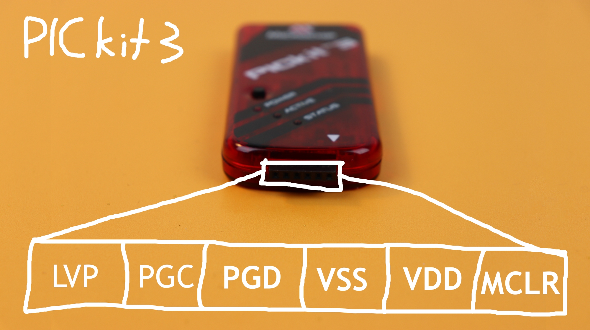
The corresponding connections on the PICkit can be seen here:
Now we can flash the .hex file onto the PIC16F883. If you want to learn more about that you can read my tutorial on flashing a .hex file onto a PIC controller.
Building the binary clock breadboard circuit
Now we are done with computers, and it is time to connect some wires! Here you can find the step-by-step instructions to assemble the binary clock circuit on the breadboard:
-

-
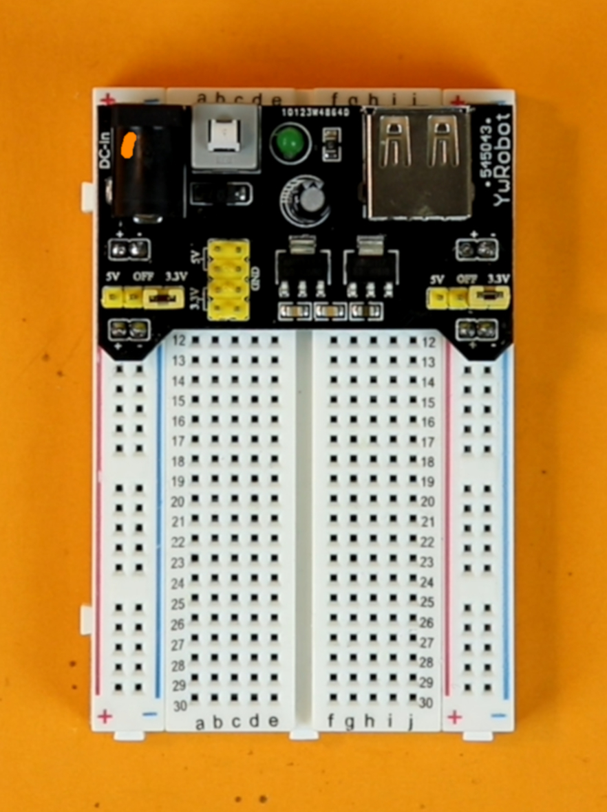
Step 1
This is your empty breadboard. Place it in front of you with the hole 1a to the top left.
-
-
Step 2
Place the USB breadboard power supply. Make sure that both jumpers are set to the 5V configuration.
As you can see in the photo, the jumpers are still set to the 3.3V configuration. This is a mistake. I did not realize this while assembling the breadboard and corrected the mistake later. (See also step 16 at the end.)
-
-
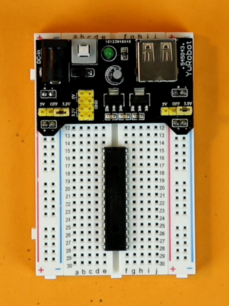
Step 3
Place the PIC16F883 controller in row 15. Make sure that the notch of the PIC16F883 points up.
Remember that the PIC16F883 on its own is useless! We need to flash it with a hex-file first. You can find a detailed introduction into that topic here :)
-
-
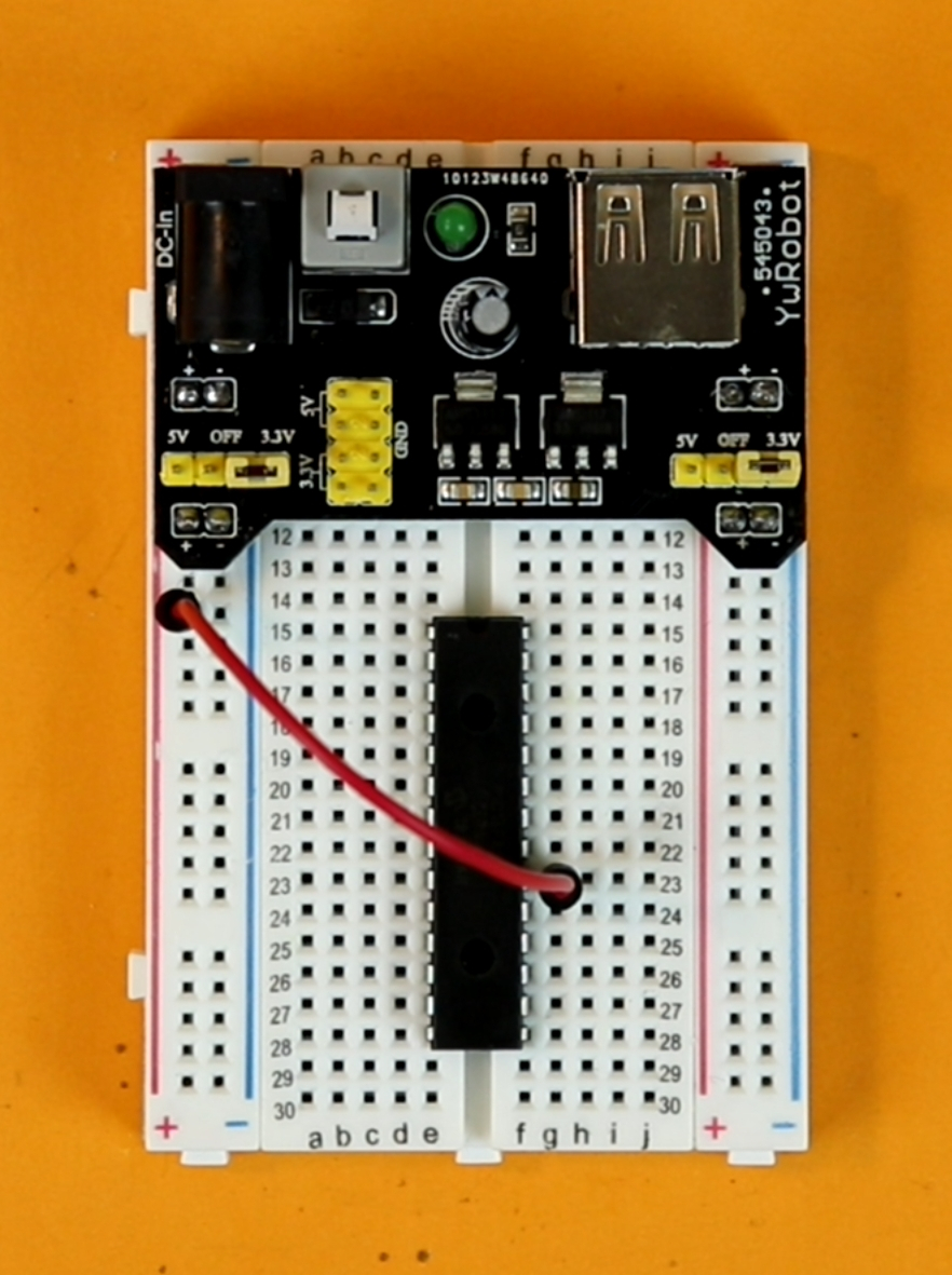
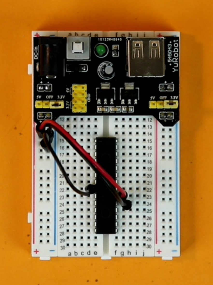
Step 4
Use a red cable to connect pin 20 (VDD) of the PIC16F883 with the +5V power rail.
-
-
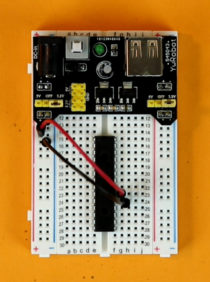
Step 5
Use a black cable to connect pin 19 (VSS) of the PIC16F883 with the ground power rail.
-
-
Step 6
Use a black cable to connect pin 8 (VSS) of the PIC16F883 with the ground power rail.
Yes, this PIC controller has two ground connections and only one VDD connection :)
-
-
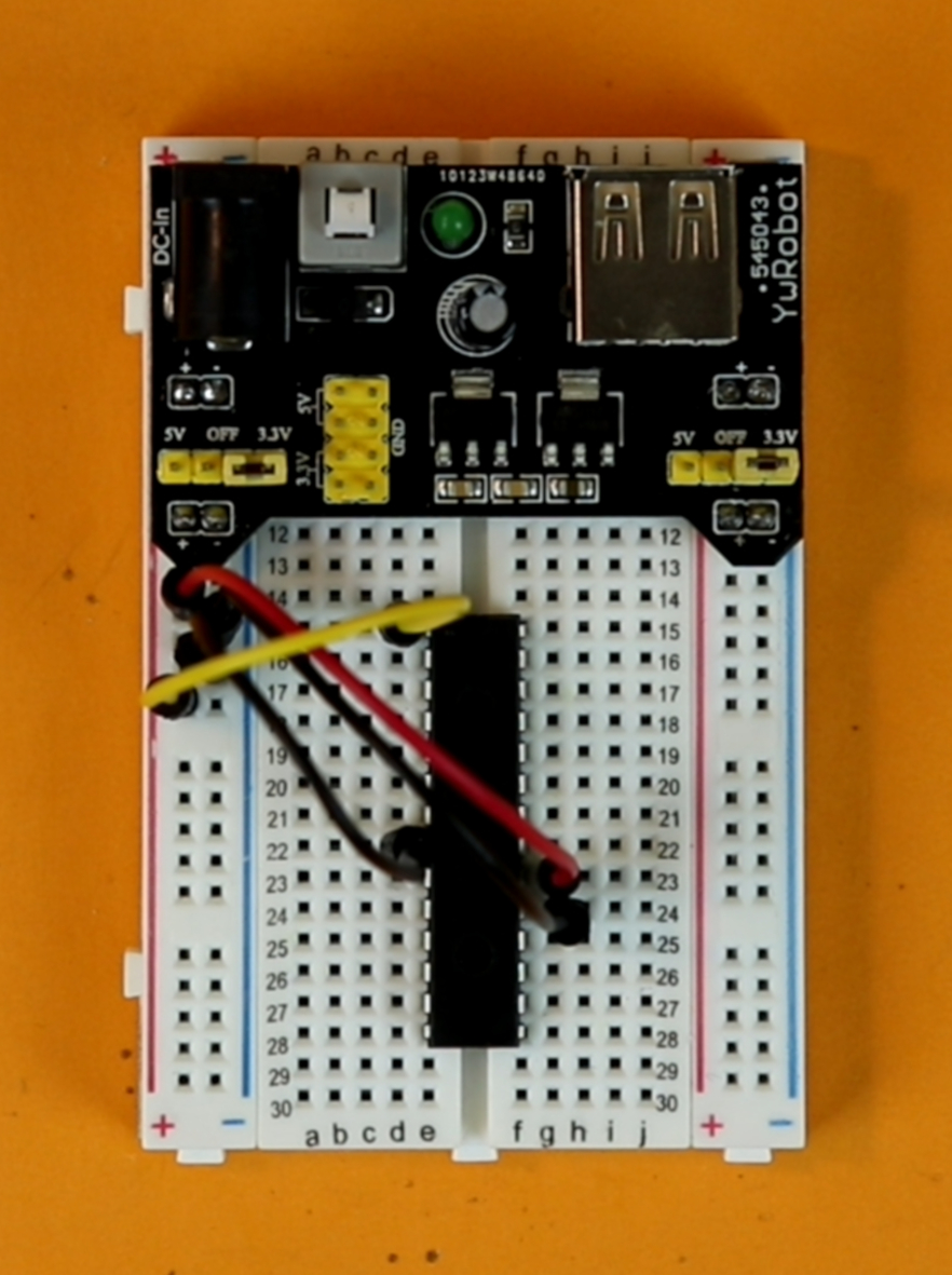
Step 7
Use a yellow cable to connect pin 1 (MCLR) of the PIC16F883 with the +5V power rail.
-
-
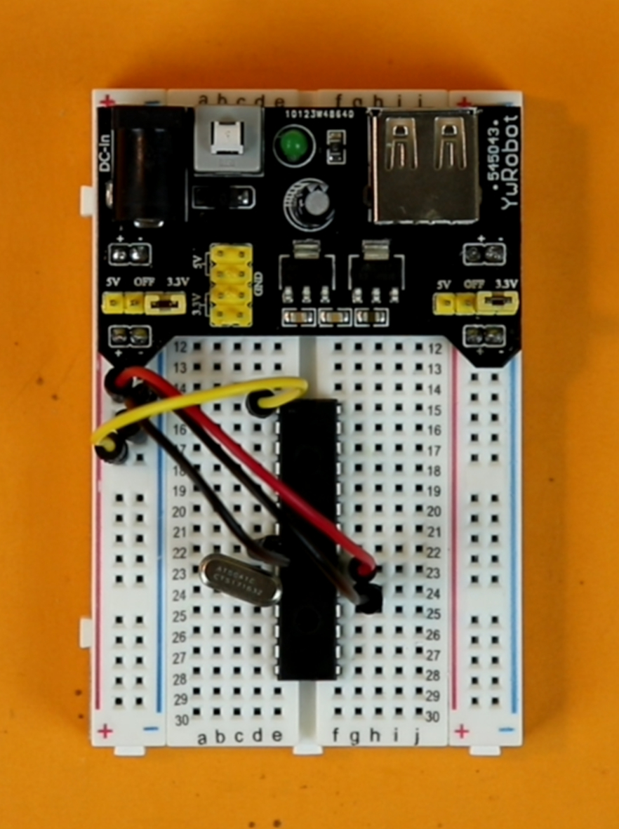
Step 8
Plug in the 4.194304MHz crystal between pins 9 and 10 of the PIC16F883. The crystal has no polarity, you can plug it in either way.
-
-
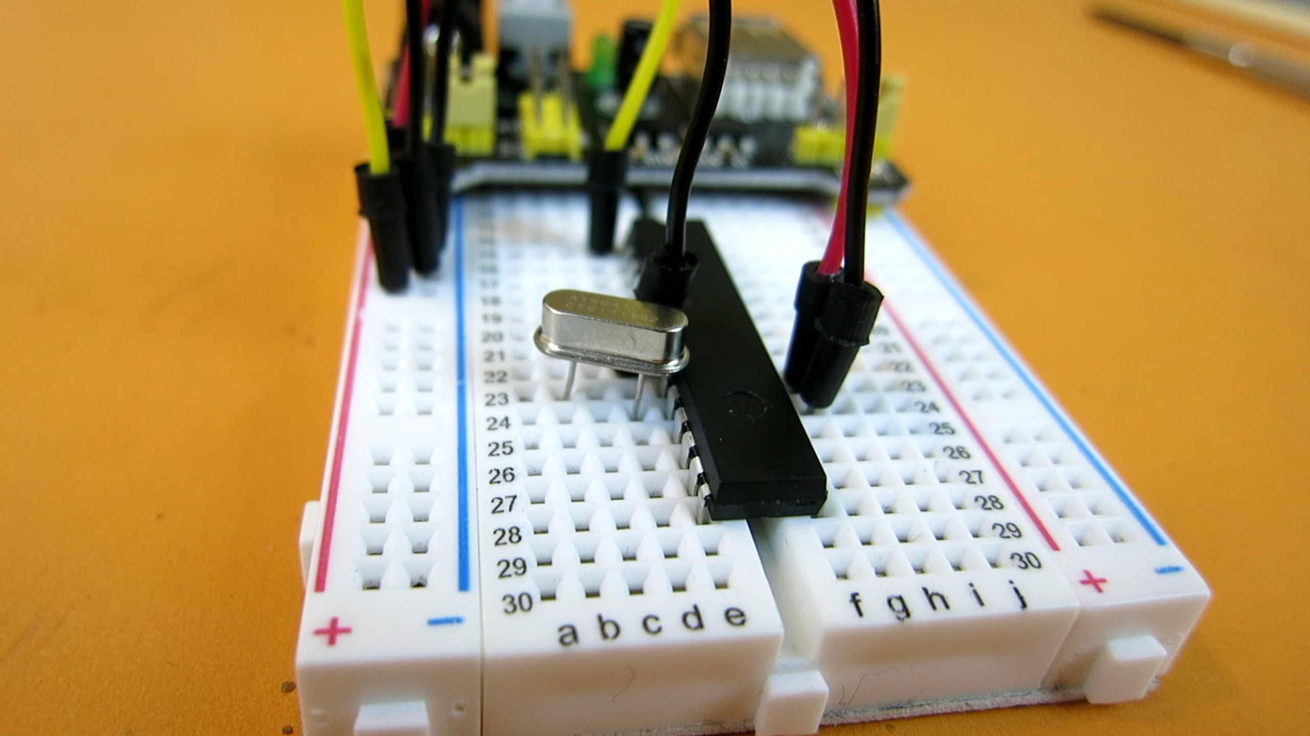
Step 8 (detail)
Here is a closeup of how the crystal is connected.
-

-
Step 9
Plug in one 22pF capacitor from pin 9 to the ground rail. Its polarity does not matter, you can plug it in either way.
-
-
Step 10
Plug in the other 22pF capacitor from pin 10 to the ground rail. Its polarity does not matter, you can plug it in either way.
-

-
Steps 9 & 10 (detail)
Here is a closeup of how the capacitors are connected.
-
-
Step 11 (optional)
If you want the clock to run in AM/PM mode, skip this step.
If you want the clock to run in 24 hour mode, connect pin 24 with ground.
-

-
Step 12
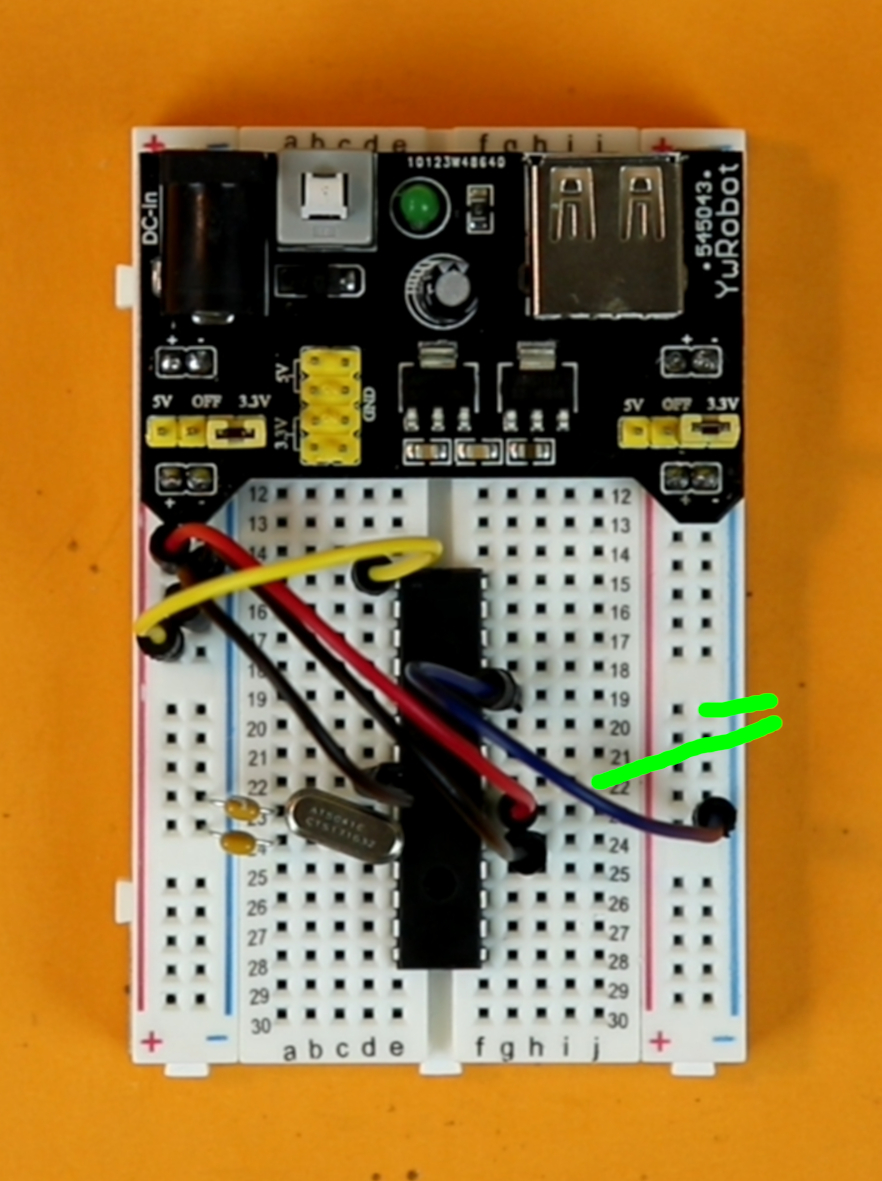
Connect all LEDs. Look at the schematic to read off all connections.
The cathode of every LED is connected to the ground rail (either side is fine). The anode of the LED is connected to the corresponding pin of the microcontroller.
For example, in the image you can see the connections for LED S0 whose anode is connected to pin 25.
Repeat this step for all LEDs.
-
-
Step 13
Connect the LED toggle switch.
It is connected between pins 21 and ground. Pin 21 means pin 21 of the PIC16F883 controller, and has nothing to do with the number printed on the breadboard.
-
-
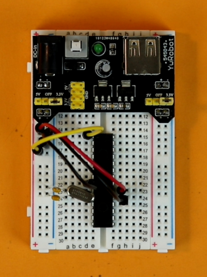
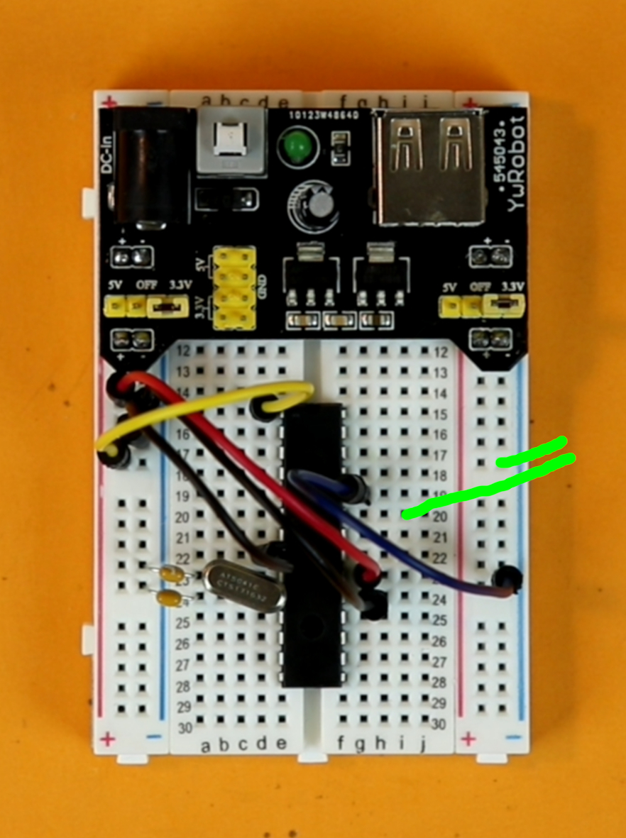
Step 14
Connect the hours pushbutton between pin 22 of the PIC16F883 and ground.
-
-
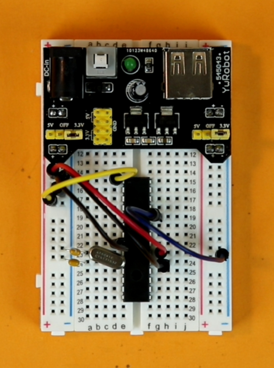
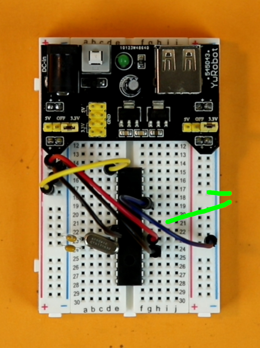
Step 15
Connect the minutes pushbutton between pin 23 of the PIC16F883 and ground.
-
-
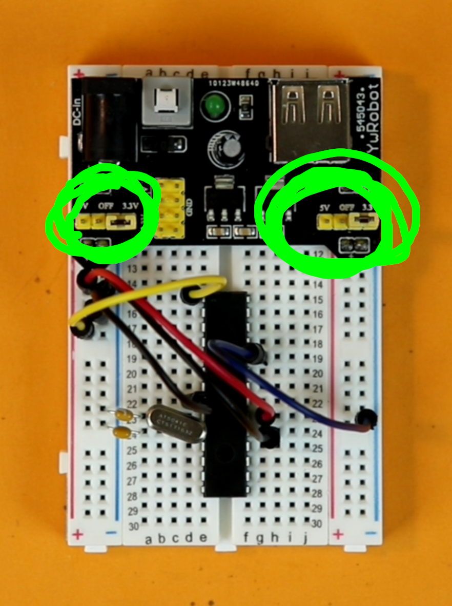
Step 16
Make sure that both jumpers are set to 5V. As you can see in the photo, the jumpers are still set to the 3.3V configuration. This is a mistake. They need to both be set to the 5V configuration.
I did not realize this while assembling the breadboard and corrected the mistake later.
And now you can plug in a USB cable into the breadboard power supply, and the clock should be working! In the rest of this article I will explain how to build the housing for the binary clock in the form of a regular in can.
Building the binary clock housing
The electronics part is already over :) But I always like to put my projects into (more or less) nice enclosures, because otherwise they end up being tossed around. In a way, building an enclosure for a project gives it more dignity ;-)
I started with a simple soup can. The label can be removed with some hot water, but the adhesive does not come off easily. I think the best solution is to employ an adhesive remover, such as Goo Gone. Spray a bit of Goo Gone on the can, and then cover it in a paper towel. Then soak it in more Goo Gone and let it sit for about ten minutes. After that the glue comes off easily:

I find it the easiest to clean the soup can when the soup is still inside because then the can has some weight to it. After all the glue is removed it comes the time to empty the can, eat the soup, and think about drilling a lot of holes into the can.
I recommend using bradpoint bits for that purpose. For the LEDs you will need 5mm bits, and the for switch and the two buttons it depends a little bit on the ones you choose. My switch works with 6mm and the pushbuttons need 7mm.

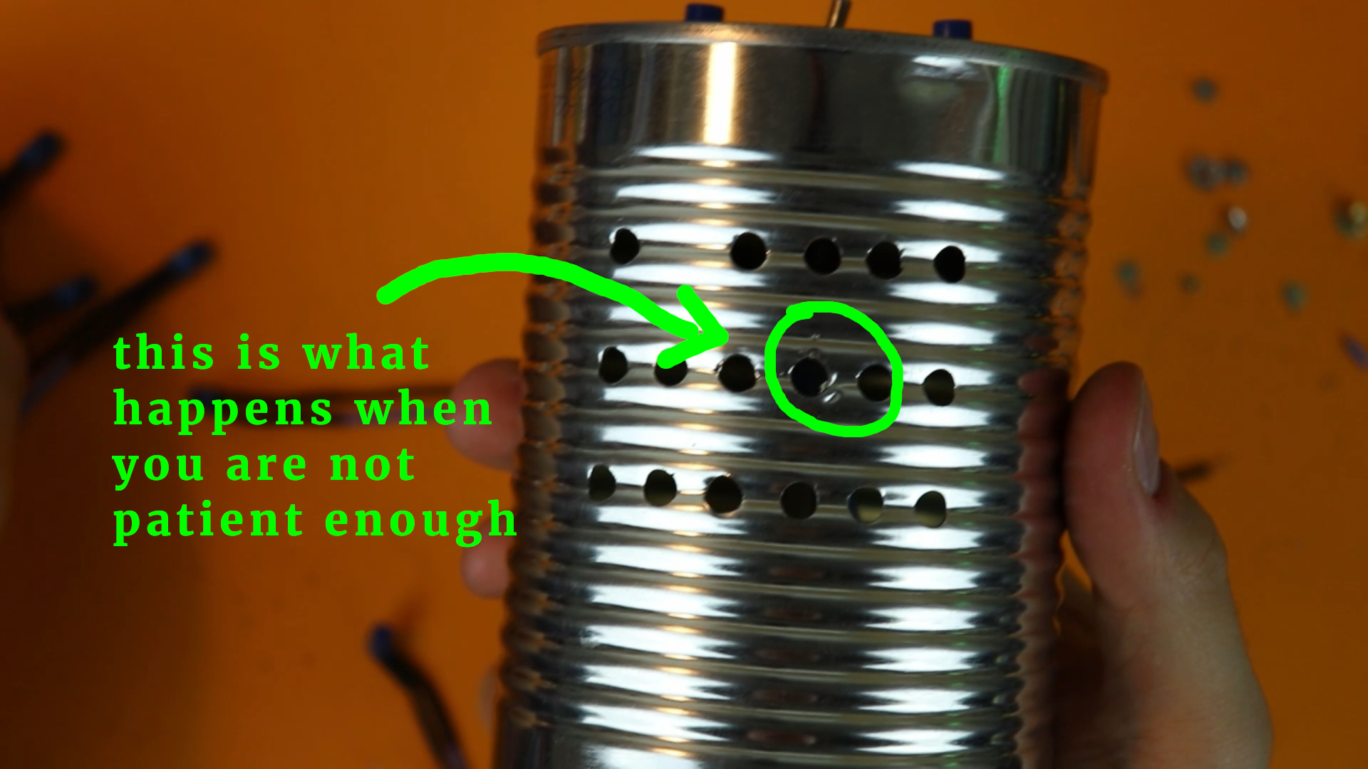
One general piece of advice: take your time while drilling! The results will be the cleanest when you take your time and don't push the drillbit too much against the can. It also helps to punch little pilot holes with a center punch (or with the tip of the 7mm bradpoint bit) so that you have a clean starting point for drilling the holes:


Most of the drilling went fine, except for one hole where I was getting impatient. See here:
After drilling all the holes it is easy to mount the switches because they come with nuts that need to be tightened:
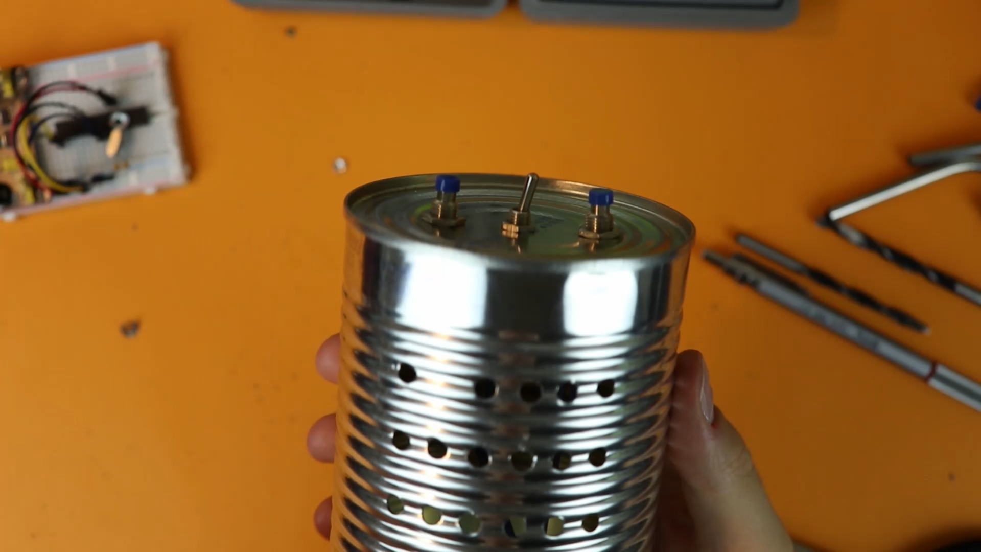
Don't mount the LEDs at this time! We first need to mount the binary clock's legs, and this is easier without the LEDs installed.
As legs I chose simple stainless steel drinking straws (20cm or 8" long). They can be mounted straightforwardly with hot glue:
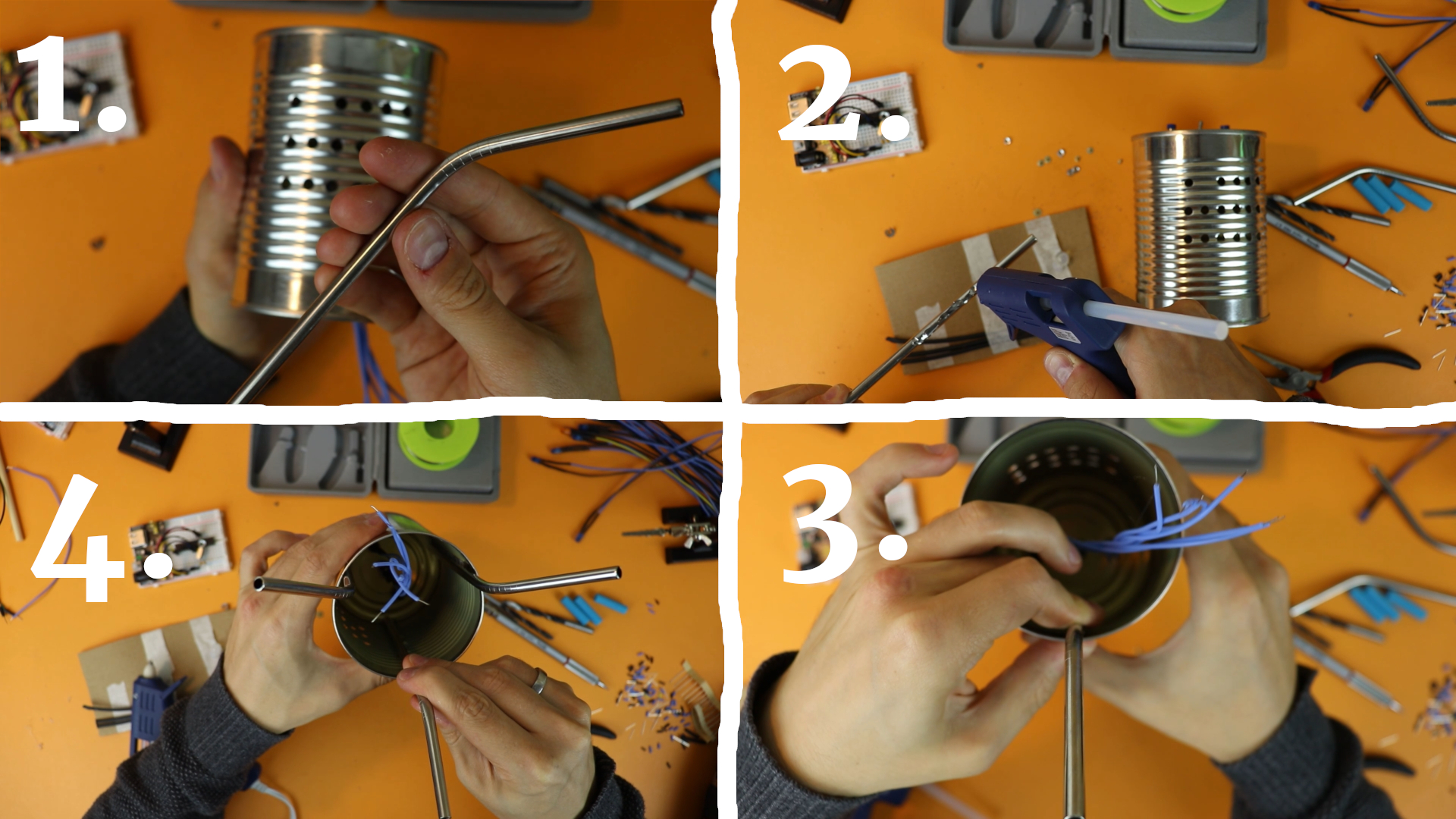
Now it is time to mount the LEDs. I bent them by 90 degrees (carefully, and only once, so that the wires don't break), added a dab of hot glue, and installed them on the inside:

Final assembly of the binary clock
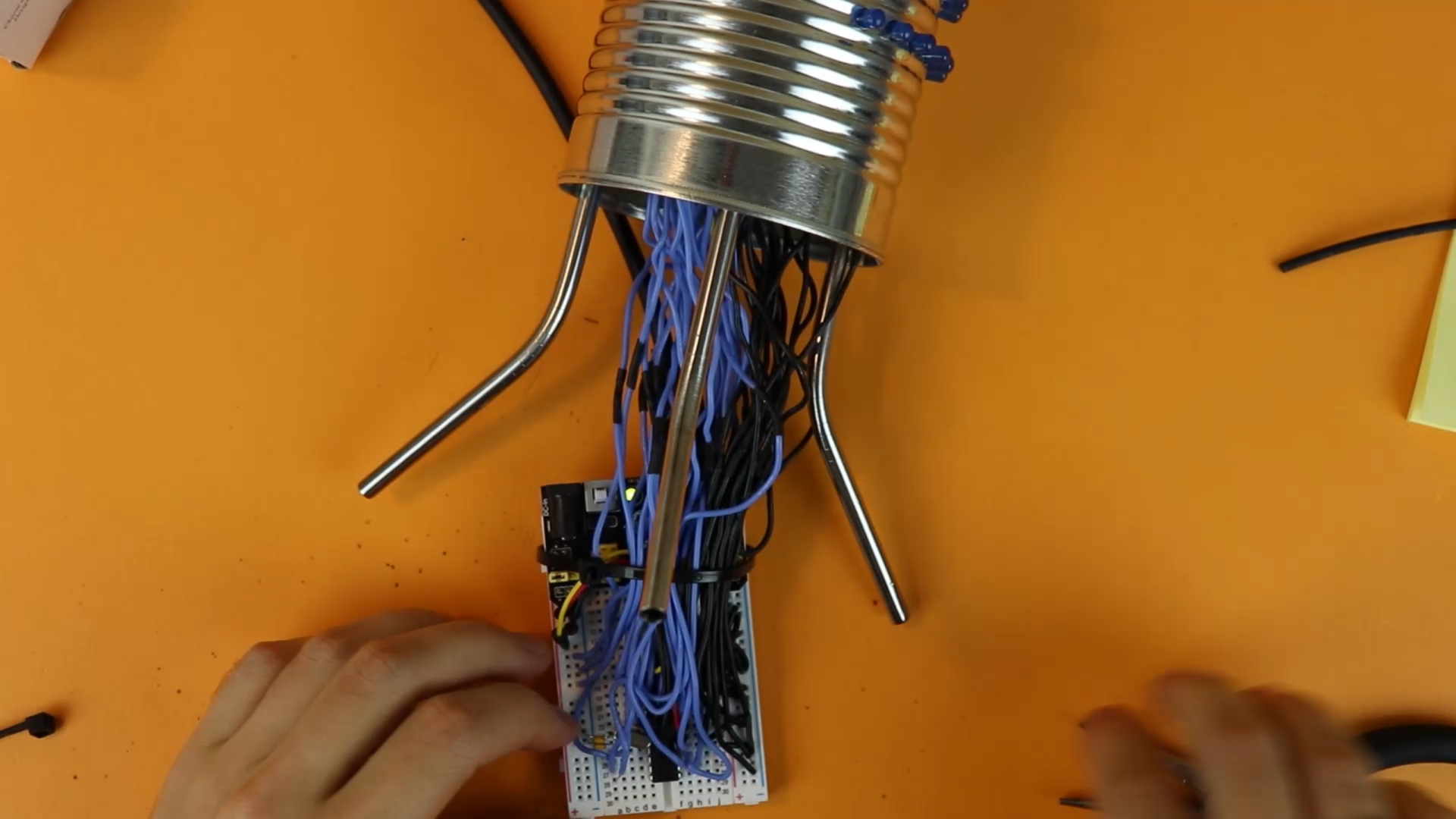
Now we are almost done! We just need to connect the LEDs. This can be a bit messy because there are many wires sticking out the bottom of the can:

There is a simple trick that will make your life a lot easier:
- Connect all black wires (the negative terminals of the LEDs) to ground.
- Power on the USB breadboard power supply by plugging in a USB cable.
- Connect a single, long wire to the positive terminal, and connect that wire to any of the blue cables sticking out the bottom of the can. Only one LED will light up (namely that LED the blue wire belongs to).
- Now that you know which LED it is, use the schematic to find the corresponding pin on the PIC16F883.
- Repeat these steps until all LEDs are connected.
Of course you also need to connect the pushbuttons and the LED toggle switch, but this should be easier because their wires are easier to locate.
After everything is wired up, carefully fix everything with a few zip ties:
Then you can fold the breadboard over and insert it into the can, carefully:
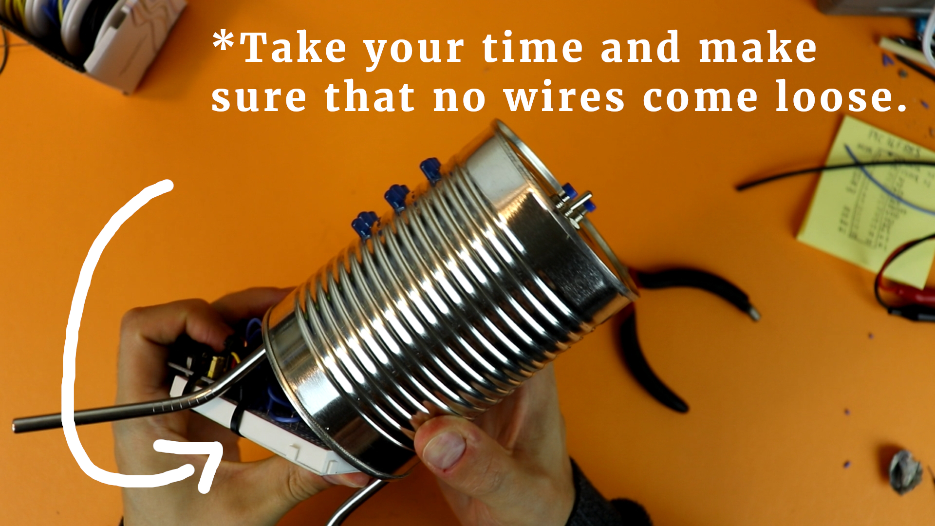
When I did this I had to try it three times because every time some wires got loose. In the end I fixed everything with zip ties and it was OK. If you made it this far, you can surely also overcome this last hurdle. I believe in you!
To secure everything in place, I added a few dabs of hot glue to the breadboard so that it doesn't shift around inside the can. Don't be shy! ;-)

And that's it! You made it! The binary clock is all finished now, congratulations!
Final thoughts

This project is quite involved, as you have probably seen. But it is also very very rewarding. When you build a project like this you can be proud of yourself! You understand every single wire inside that machine :)
It is probably a good idea to connect the binary clock to a USB battery bank because once you unplug the USB cable the clock loses its time. When you use a battery bank there is at least a small buffer: small fluctuations in the mains voltage won't lead to the clock losing it's time, provided you charge the battery bank regularly.
I hope this article inspires you to build something yourself! Please let me know if you feel that some important piece of information is missing from this article. I tried my best to do a good job of writing this up, but after some time you get tunnel vision and perhaps I missed something important. You can get ahold of me quite easily on social media and I will do my best to answer your questions :)
Thank you for reading, and I'll see you around!
YouTube video
I covered this entire project in a dedicated YouTube video:
Appendix: full source code
Here is the full source code you can compile with the XC8 C compiler for PIC microcontrollers. You can also directly download the .hex file in the resources box of this article.
/*
 * File:   main.c
 * Author: boos
 *
 * Created on July 12, 2019, 7:46 PM
 */

// CONFIG1
#pragma config FOSC = XT        // Oscillator Selection bits (XT oscillator: Crystal/resonator on RA6/OSC2/CLKOUT and RA7/OSC1/CLKIN)
#pragma config WDTE = OFF       // Watchdog Timer Enable bit (WDT disabled and can be enabled by SWDTEN bit of the WDTCON register)
#pragma config PWRTE = OFF      // Power-up Timer Enable bit (PWRT disabled)
#pragma config MCLRE = ON       // RE3/MCLR pin function select bit (RE3/MCLR pin function is MCLR)
#pragma config CP = OFF         // Code Protection bit (Program memory code protection is disabled)
#pragma config CPD = OFF        // Data Code Protection bit (Data memory code protection is disabled)
#pragma config BOREN = ON       // Brown Out Reset Selection bits (BOR enabled)
#pragma config IESO = OFF       // Internal External Switchover bit (Internal/External Switchover mode is disabled)
#pragma config FCMEN = OFF      // Fail-Safe Clock Monitor Enabled bit (Fail-Safe Clock Monitor is disabled)
#pragma config LVP = OFF        // Low Voltage Programming Enable bit (low voltage programming disabled)

// CONFIG2
#pragma config BOR4V = BOR40V   // Brown-out Reset Selection bit (Brown-out Reset set to 4.0V)
#pragma config WRT = OFF        // Flash Program Memory Self Write Enable bits (Write protection off)

#include <xc.h>

// define names

#define ONOFF RB0
#define SWH RB1
#define SWM RB2
#define H24 RB3

#define S0  RB4
#define S1  RB5
#define S2  RB6
#define S3  RB7
#define S4  RC0
#define S5  RC1

#define M0  RC2
#define M1  RC3
#define M2  RC4
#define M3  RC5
#define M4  RC6
#define M5  RC7

#define H0  RA1
#define H1  RA2
#define H2  RA3
#define H3  RA4
#define PM  RA5

// these variables store the time
unsigned char seconds = 0, minutes = 0, hours = 0, hours12 = 0;

// time buffer
int TIME_BUFFER = 0;

// switch debounce buffers
int SWH_BUFFER = 0;
int SWM_BUFFER = 0;

// the main function
void main (void) {

    // enable weak pull-up resistors on PORTB
    nRBPU = 0;

    // switch OFF the analog to digital converter (ADC)
    // because we do not need it here
    ADON = 0;
    ANS0 = 0;
    ANS1 = 0;
    ANS2 = 0;
    ANS3 = 0;
    ANS4 = 0;
    ANS8 = 0;
    ANS9 = 0;
    ANS10 = 0;
    ANS11 = 0;
    ANS12 = 0;
    ANS13 = 0;

    // these pins are inputs
    TRISB0 = 1;
    TRISB1 = 1;
    TRISB2 = 1;
    TRISB3 = 1;

    // and all of these pins are outputs
    TRISB4 = 0;
    TRISB5 = 0;
    TRISB6 = 0;
    TRISB7 = 0;
    TRISC0 = 0;
    TRISC1 = 0;
    TRISC2 = 0;
    TRISC3 = 0;
    TRISC4 = 0;
    TRISC5 = 0;
    TRISC6 = 0;
    TRISC7 = 0;
    TRISA1 = 0;
    TRISA2 = 0;
    TRISA3 = 0;
    TRISA4 = 0;
    TRISA5 = 0;

    // initialize TIMER0

    // TIMER0 works with 1/4 of the internal clock
    // (that amounts to 1.048576 MHz)
	T0CS = 0;

	// set the TIMER0 prescaler to 1:1
	PSA = 1;
	PS0 = 1;
	PS1 = 1;
	PS2 = 1;

	// create an interrupt when TIMER0 overflows
	T0IE = 1;

    // enable interrupts
	GIE = 1;

    // the main loop
    while (1) {

        // only show the time if the toggle
        // switch is turned to the ON position
        if (!ONOFF) {

            // show seconds
            S0 = (seconds & 0b000001) >> 0;
            S1 = (seconds & 0b000010) >> 1;
            S2 = (seconds & 0b000100) >> 2;
            S3 = (seconds & 0b001000) >> 3;
            S4 = (seconds & 0b010000) >> 4;
            S5 = (seconds & 0b100000) >> 5;

            // show minutes
            M0 = (minutes & 0b000001) >> 0;
            M1 = (minutes & 0b000010) >> 1;
            M2 = (minutes & 0b000100) >> 2;
            M3 = (minutes & 0b001000) >> 3;
            M4 = (minutes & 0b010000) >> 4;
            M5 = (minutes & 0b100000) >> 5;

            // show hours in AM/PM format
            if (H24) {

                // convert to 12 hour display
                hours12 = hours;
                if (hours > 12) {
                    hours12 -= 12;
                } else if (hours == 0) {
                    hours12 = 12;
                }
                H0 = (hours12 & 0b000001) >> 0;
                H1 = (hours12 & 0b000010) >> 1;
                H2 = (hours12 & 0b000100) >> 2;
                H3 = (hours12 & 0b001000) >> 3;

                // PM indicator
                if (hours > 11) {
                    PM = 1;
                } else {
                    PM = 0;
                }

            // show hours in 24 hour format
            } else {

                H0 = (hours & 0b000001) >> 0;
                H1 = (hours & 0b000010) >> 1;
                H2 = (hours & 0b000100) >> 2;
                H3 = (hours & 0b001000) >> 3;
                PM = (hours & 0b010000) >> 4;

            }

            // adjust hours?
            if ((!SWH) && (SWH_BUFFER == 0)) {
                SWH_BUFFER = 1000;
                hours++;
                if (hours >= 24) {
                    hours = 0;
                }
                seconds = 0;
            }

            // adjust minutes?
            if ((!SWM) && (SWM_BUFFER == 0)) {
                SWM_BUFFER = 1000;
                minutes++;
                if (minutes >= 60) {
                    minutes = 0;
                }
                seconds = 0;
            }


        // switch all LEDs off if the toggle switch
        // is set to the OFF position
        } else {

            S0 = 0;
            S1 = 0;
            S2 = 0;
            S3 = 0;
            S4 = 0;
            S5 = 0;
            M0 = 0;
            M1 = 0;
            M2 = 0;
            M3 = 0;
            M4 = 0;
            M5 = 0;
            H0 = 0;
            H1 = 0;
            H2 = 0;
            H3 = 0;
            PM = 0;

        }

    }

    return;

}

// the interrupt service routine
// (this routine gets called 4096 times a second)
void __interrupt () isr (void) {

    // has TIMER0 reached its maximum?
	if (T0IF) {

        // increase the buffer variable
        // whenever TIMER0 overflows
        TIME_BUFFER++;

        // has it overflown 4096 times?
        // then one second has passed!
        if (TIME_BUFFER >= 4095) {

            // reset buffer
            TIME_BUFFER = 0;

            // update the time
            seconds++;
            if (seconds >= 60) {
                seconds = 0;
                minutes++;
                if (minutes >= 60) {
                    minutes = 0;
                    hours++;
                    if (hours >= 24) {
                        hours = 0;
                    }
                }
            }

        }

        // debounce switches
        if (SWH_BUFFER > 0) {
            SWH_BUFFER--;
        }
        if (SWM_BUFFER > 0) {
            SWM_BUFFER--;
        }

		// IMPORTANT: reset the interrupt flag!
		T0IF = 0;

	}

}


