Build your own electronic dice!
June 7, 2019 • project
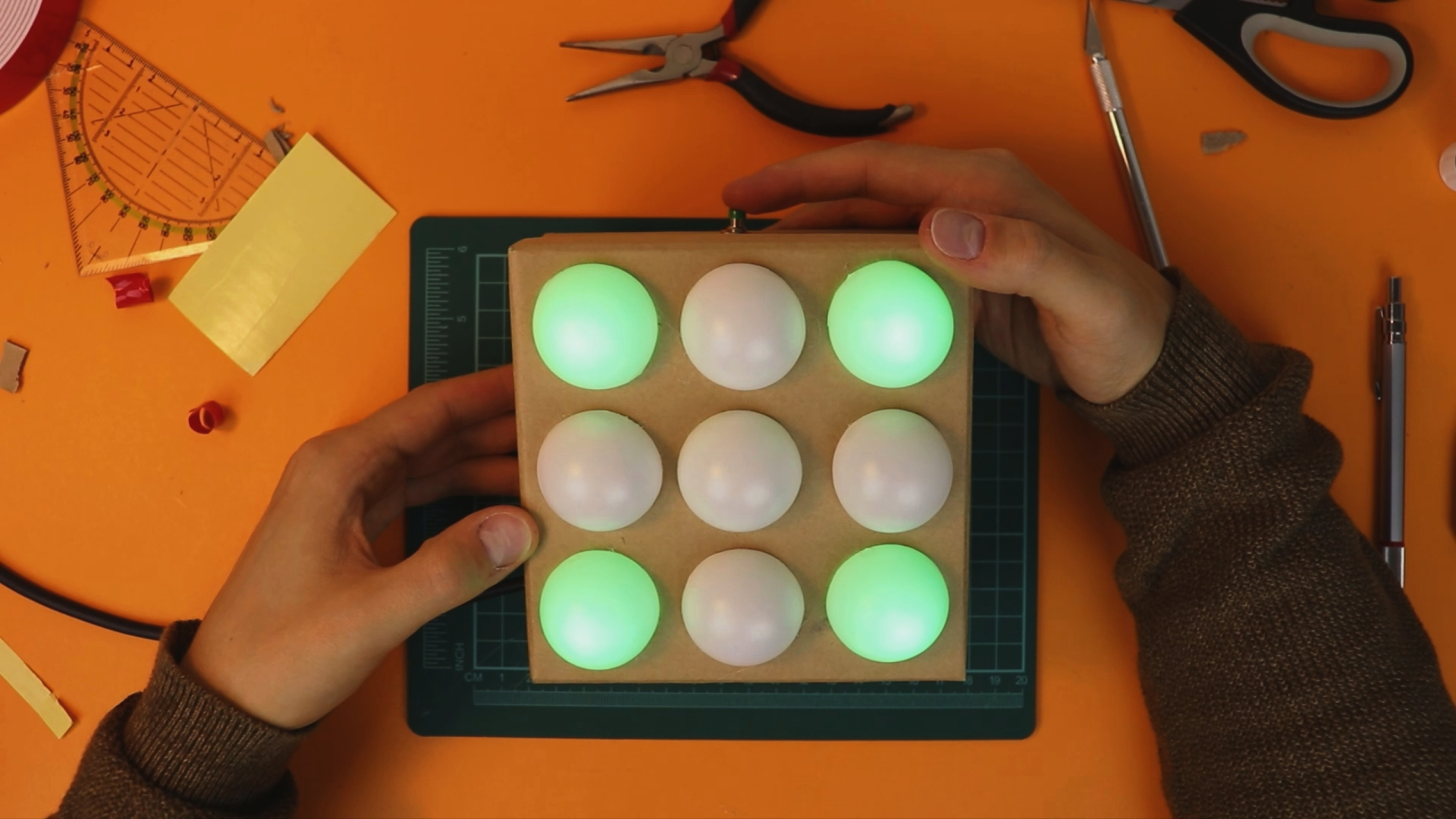
In the last weeks we have learned a lot about the basics on microcontrollers. In this project, we will combine all that knowledge. We will use a pushbutton, nine LEDs, and a microcontroller to make an electronic dice! How does it work? By pressing the pushbutton, the nine LEDs act as the spots of the dice and show a random* number. Let's do it! :)
*Actually the number is anything but random, more on that below.
Overview: the electronic dice!
This is the first real project we are tackling, and naturally, it is more complex than the stuff we have talked about before. I can assure you: with the previous knowledge that we developed you can totally do this :) It takes a bit of work, that's true, but in the end it will be worth it!
Just to make sure that we are on the same page, here are the previous blog posts that are relevant for this project:
- Your first PIC microcontroller program
- How to “flash” a PIC?
- Your first microcontroller project: make an LED blink!
- How to read out a pushbutton?
If you read these articles from start to finish (there is also a YouTube video if you like that more) you will be in pretty good shape to tackle this project! If there is something completely unclear in this project, please get in touch on social media and we will figure it out :)
What components do you need?
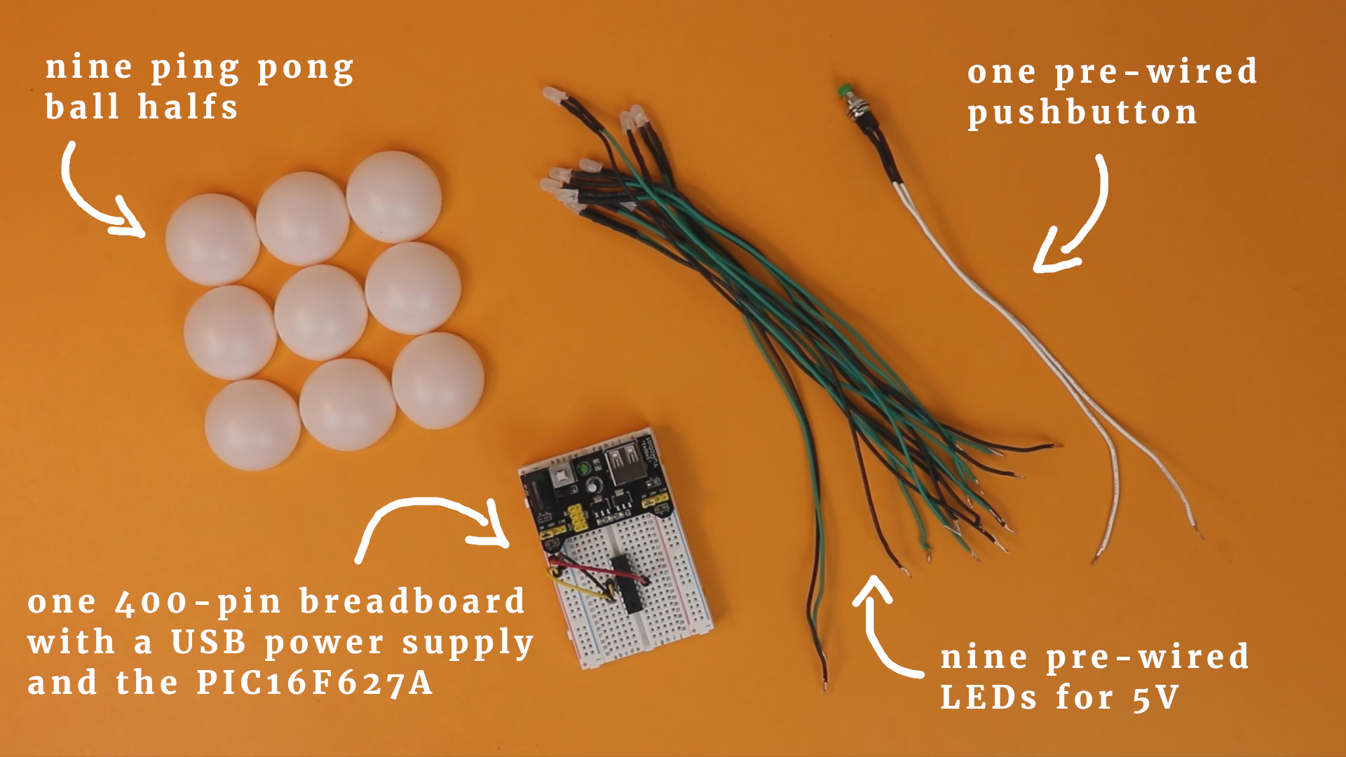
I compiled a detailed list of everything that is needed on the right side of this article (if you are on a desktop) or at the bottom of this article (if you are on mobile). Here you can see an picture of the main components:
I recommend to get cheap ping pong balls, not high-quality ones. This way you save some money, and it turns out that cheap ping pong balls are actually better for this project:
- They are thinner and easier to cut in half.
- Because they are thinner they let through a bit more light, which can be nice if your LEDs are not terribly bright.
Speaking of LEDs, it is a good idea to get very bright ones. Also, get a simple cardboard box from the dollar store as the enclosure for the dice:
What tools do you need?
Sometimes it is easy to forget that not everybody has a fully equipped workshop at home. This is why I tried to keep the tools required for this project at an absolute minimum. Here is what you will most likely need:
- The PICkit3 for programming the PIC16F627A microcontroller (as well as five wires, a 6-pole pin header, and a 400-pin breadboard to build the programming board, read more here).
- An X-Acto knife/box cutter and cutting board.
- A hot glue gun.
- A drill and a 5mm drill bit to drill the holes for the LEDs (you can get away with cutting them with a knife, too).
- A ruler or a digital caliper.
- A pencil.
Alright, enough chit chat, let's get to it!
Software and .hex file
As with any microcontroller project, we have to write a program to tell the controller what to do. In this case, we want the controller to do the following:
- Control nine LEDs that are arranged in the shape of a dice.
- React to the pressing of a pushbutton.
- Show a random dice number when the button is released.
This program is written in C for the XC8 compiler, and we will use MPLAB IDE X to write the program and MPLAP IPE X to flash it onto the controller.
You can find the full source code in the appendix; in what follows, we will go through the code line by line and explain what it does :)
#include <xc.h>This line just loads the basic XC8 compiler macros, it is present in all projects.
// BEGIN CONFIG
#pragma config FOSC = INTOSCIO
#pragma config WDTE = OFF
#pragma config PWRTE = OFF
#pragma config MCLRE = ON
#pragma config BOREN = OFF
#pragma config LVP = OFF
#pragma config CPD = OFF
#pragma config CP = OFF
//END CONFIG
These lines set the configuration bits of the PIC16F627A. The only important line, really, is line 11, that tells the PIC16F627A to use its internal oscillator as a clock source. Otherwise we would have to connect an external crystal to act as a clock for the controller.
// define ports for LEDs
#define LED1 RB0
#define LED2 RB1
#define LED3 RB2
#define LED4 RB3
#define LED5 RB4
#define LED6 RB5
#define LED7 RB6
#define LED8 RA0
#define LED9 RA1

// define port for switch
// (note the "!" which inverts the status, see below)
#define BUTTON !RB7
We tell the controller where we will connect the LEDs as well as the button. Because we will use internal pulldown-resistors, we define the button to be the inverted signal of the pin RB7.
void main(void) {

  // enable weak pull-up resistors on PORTB
  nRBPU = 0;
The main function begins, and we enable the weak internal pullup resistors. This way we do not need an external resistor for the pushbutton, see also the this tutorial.
  // all LEDs are outputs
  TRISB0 = 0;
  TRISB1 = 0;
  TRISB2 = 0;
  TRISB3 = 0;
  TRISB4 = 0;
  TRISB5 = 0;
  TRISB6 = 0;
  TRISA0 = 0;
  TRISA1 = 0;

  // the switch is an input
  TRISB7 = 1;
We set the TRISTATE registers to tell the PIC16F627A controller that the LEDs are outputs and the pushbutton is an input.
  // switch off comparator at port A
  CMCON = 0b111;
This line is a bit cryptic, it's OK if it confuses you :) We need this command so that we can use the pins RA0 and RA1 as outputs. By default, these pins have an advanced functionality, but we don't need this stuff for this simple project. This is why we turn it off.
static unsigned char counter = 0;
The variable counter will store the current number that is to be displayed on the dice, more on that below.
static int buffer = 0;
The variable buffer is an auxiliary variable. We use it so that upon releasing the button the dice does not stop immediately but keeps on “rolling” for a bit to make the effect more realistic. I will explain this in more detail below.
  // main loop
  while(1) {

    // when the button is pressed, keep advancing the dice number
    // (this happens really fast and makes the number "random")
    if (BUTTON) {
      counter++;
      if (counter > 11) {
          counter = 0;
      }
      buffer = 1500;
The main loop begins! In line 70 we check if the button is held down. If so, then we increase the counter variable by one increment. This gets run over and over and over again, as long as the button is pressed. As a result, the counter variable increases many hundreds of times per second.
This is what creates the randomness of the dice throw. After only a few parts of a second, us slow humans have no way of telling where the dice is at.
      // when the button is released, reduce the buffer variable
    // one by one. Whenever it passes 100 steps, advance the
    // dice number by one.
    } else {
        if (buffer > 0) {
            buffer--;
            if (buffer % 100 == 0) {
                counter++;
                if (counter > 11) {
                    counter = 0;
                }
            }
        }
    }
Line 80 checks if the button is released. Now the buffer variable comes to play. Previously, in line 75, this variable was set to 1500 as long as the button is pressed.
But now, when it is released, it gets reduced by one count, one by one, until it reaches zero. Then it stays at zero (line 81). But also, every hundred clicks (line 83) we increase the counter is increased. This way the dice keeps rolling, at a slower speed, when the button is released.
Of course the dice does not keep rolling forever, only as long as the buffer is positive.
  if (counter == 0) {
        LED1 = 0;
        LED2 = 0;
        LED3 = 0;
        LED4 = 0;
        LED5 = 1;
        LED6 = 0;
        LED7 = 0;
        LED8 = 0;
        LED9 = 0;
The remaining lines are all very similar. They check which value the counter variable takes. Each value (0 through 11) is then converted into a special number on the dice.
But wait, you say, why do we need 12 states for that? Doesn't a regular dice only have six sides?
That is quite true! But I thought it would be funny if the dice result could also be turned around by 90 degrees:
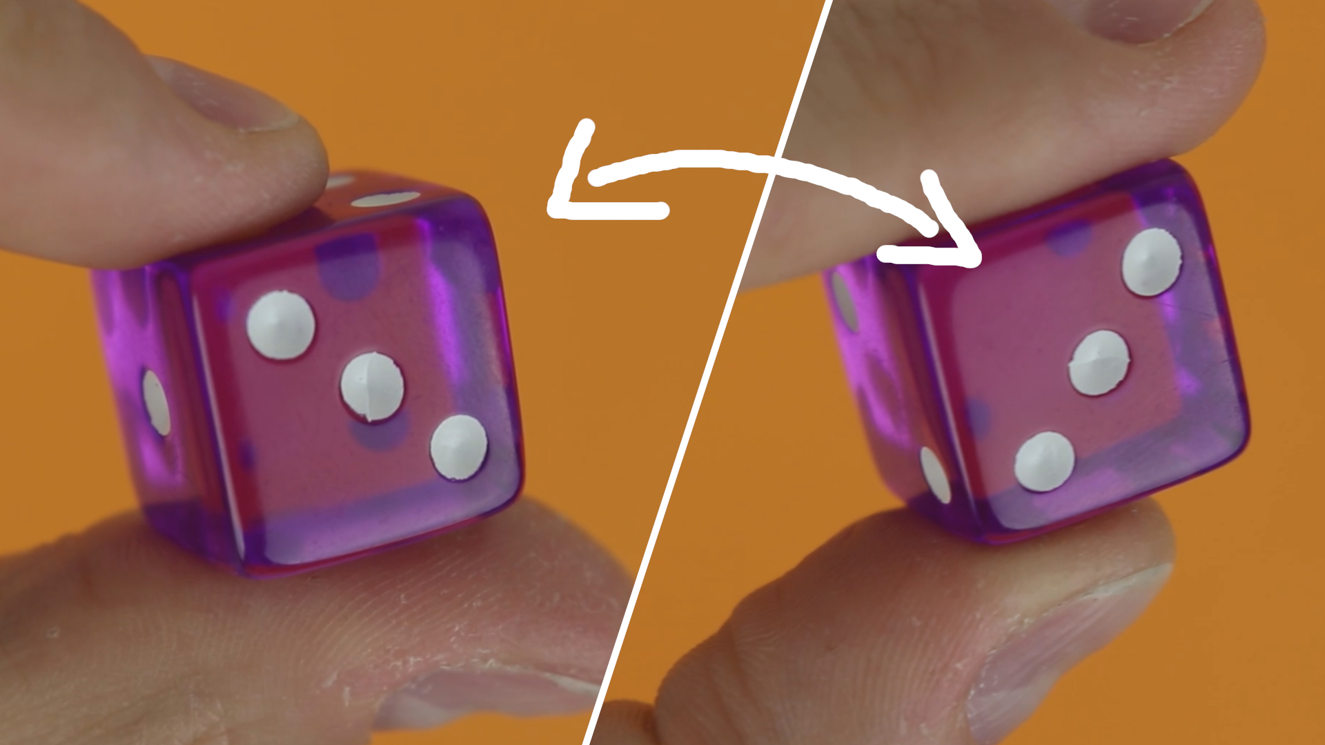
This is why there are 12 states in total. For half of the numbers the 90-degree rotated ones are identical (1,4,5), but for the others (2,3,6) there are two patterns. We need to double each number (and not just the different ones) because otherwise the probability for the rotated ones would be higher :)
And that's the code! We now need to compile it into a .hex file and flash it onto the controller. This is described in detail here and here :)
The full source code is in the appendix below, and you can download the .hex file in the resource box of this article.
Schematic and assembling the breadboard
This is the schematic of the electronic dice:
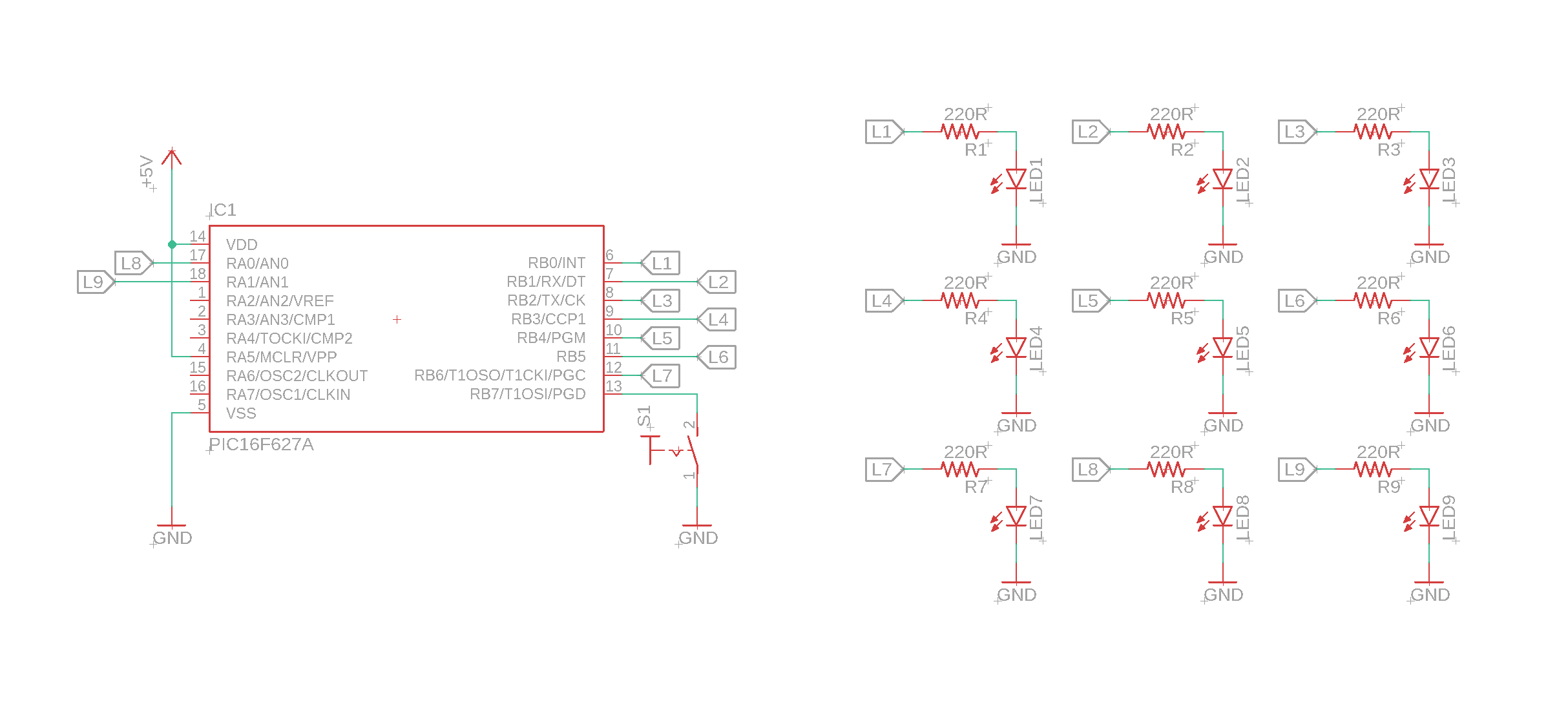
If this looks confusing to you, have a look at last week's article. The schematic was created with Autodesk's Eagle software, a link to which you can find in the resource box. OK, let's talk about the schematic!
- On the left you can see the PIC16F627A microcontroller, which is the heart and brain of the electronic dice. It is connected to a pushbutton and nine LEDs, and that's pretty much it. Don't forget to also connect the MCLR (Master Clear) pin to +5V, because otherwise the PIC16F627A will keep on resetting.
- On the right you see the nine LEDs. They are connected to the outputs of the PIC16F627A controller. I did not draw the lanes explicitly but used labels instead, and lanes of the same name have to be connected.
Okay, now that we understand the schematic we need to build it! Fortunately it is not very complicated, and you can break it down into nine simple steps. Here we go:
-
-
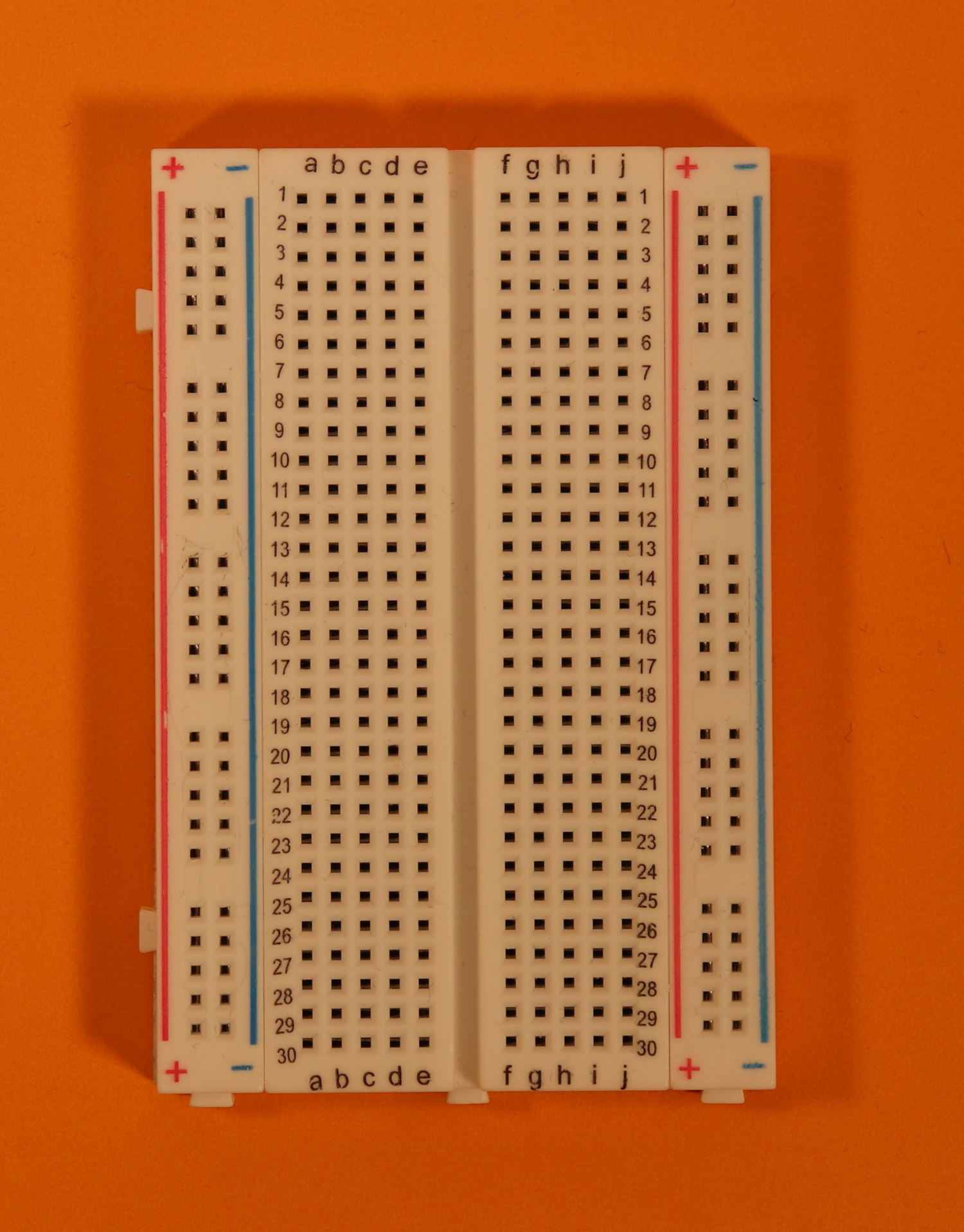
Step 1
This is your empty breadboard. Place it in front of you with the hole 1a to the top left.
-
-
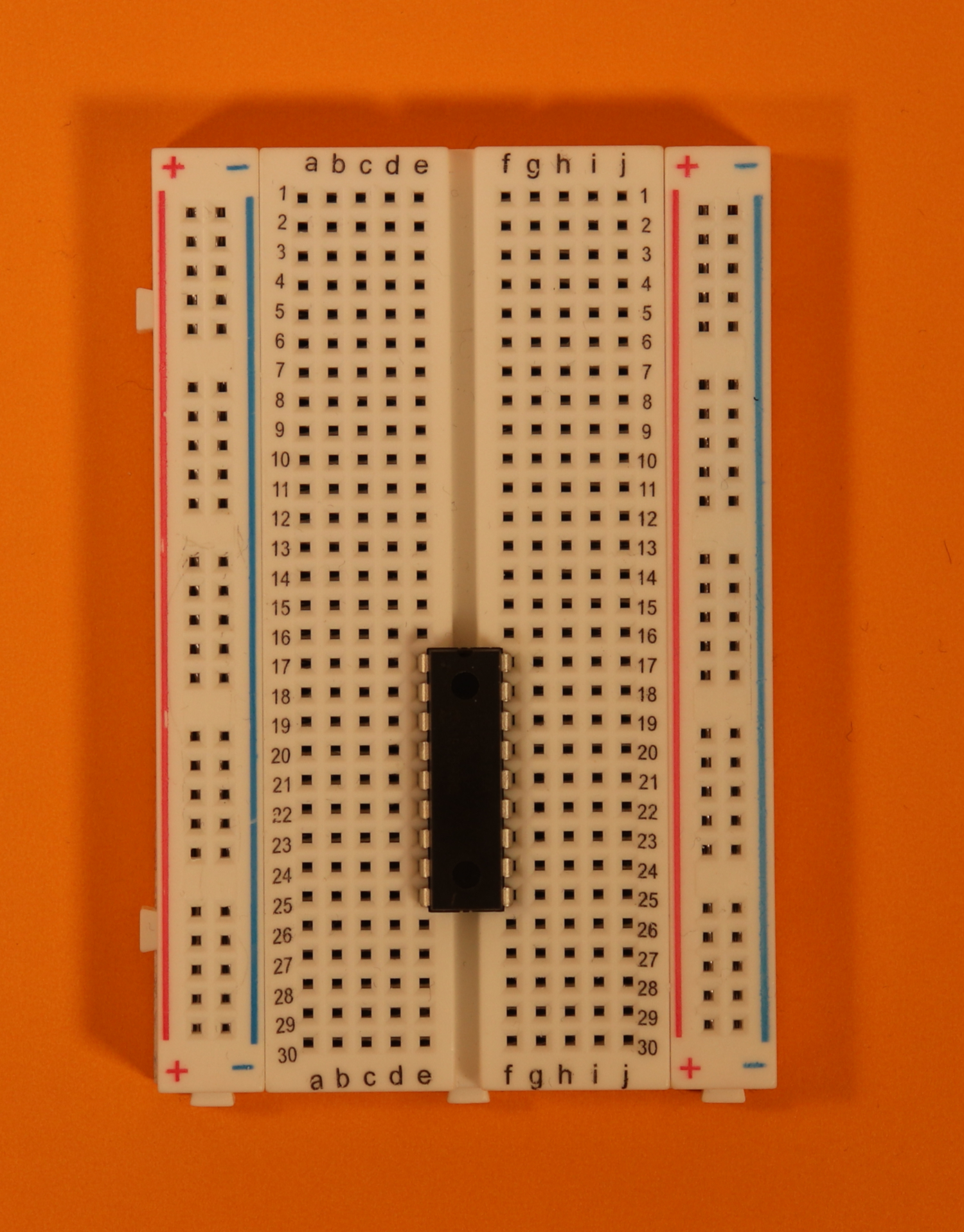
Step 2
Place the PIC16F627A controller in row 17. Make sure that the notch of the PIC16F627A points up.
See more below under troubleshooting.
Remember that the PIC16F627A on its own is useless! We need to flash it with a hex-file first. You can find a detailed introduction into that topic here :)
-
-
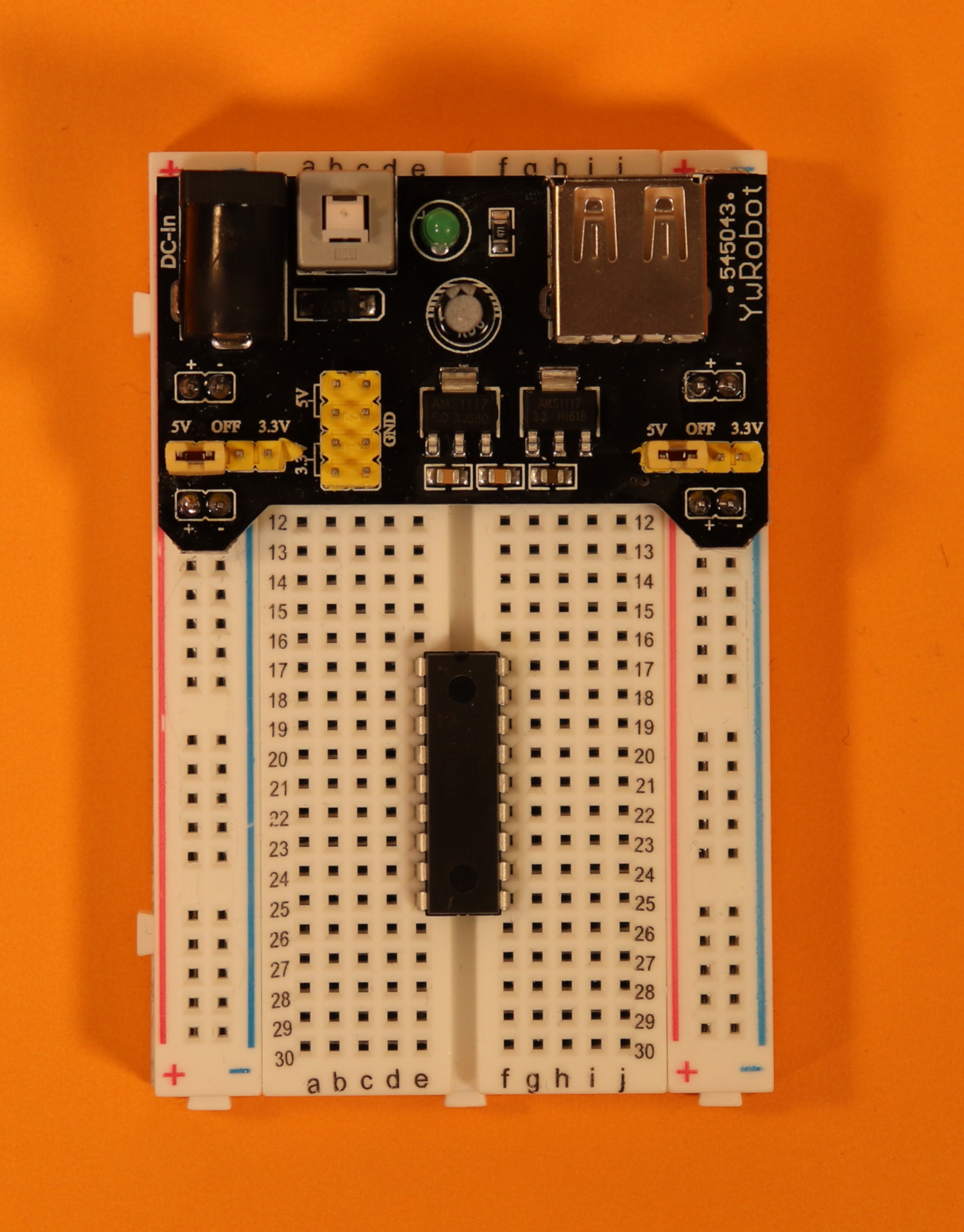
Step 3
Place the USB breadboard power supply. Make sure that both jumpers are set to the 5V configuration.
See more below under troubleshooting.
-
-
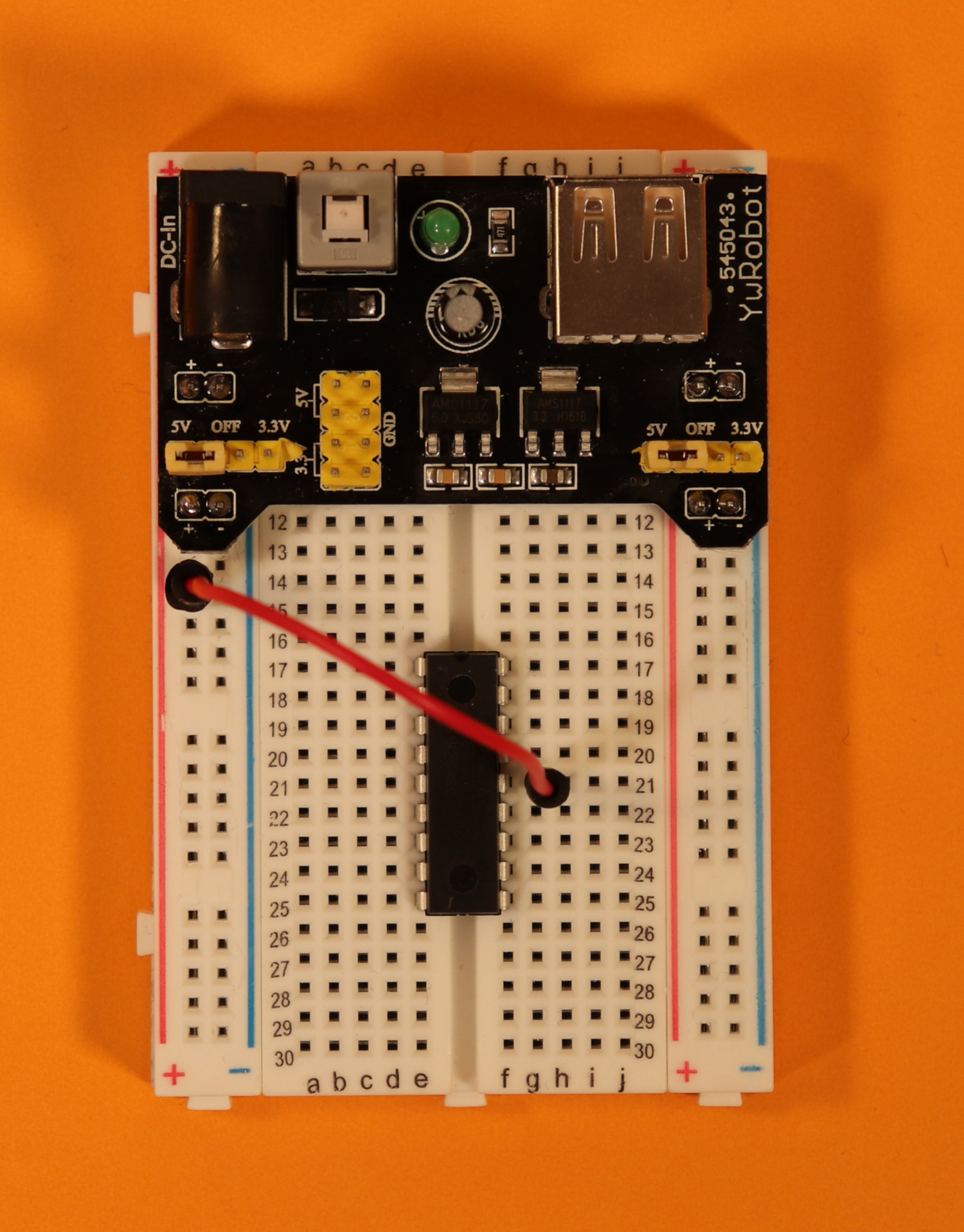
Step 4
Use a red cable to connect pin 14 (VDD) of the PIC16F627A with the +5V power rail.
-
-
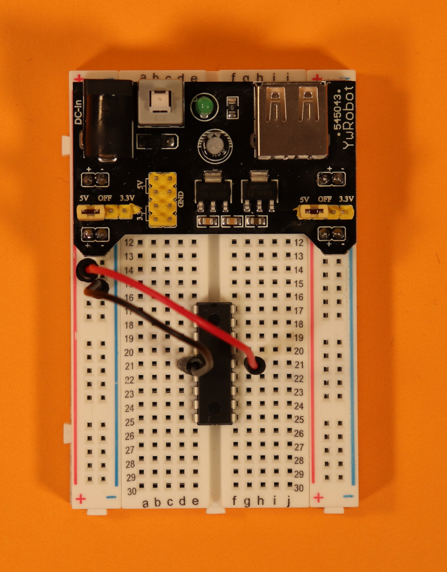
Step 5
Use a black cable to connect pin 5 (VSS) of the PIC16F627A with the ground power rail.
-
-
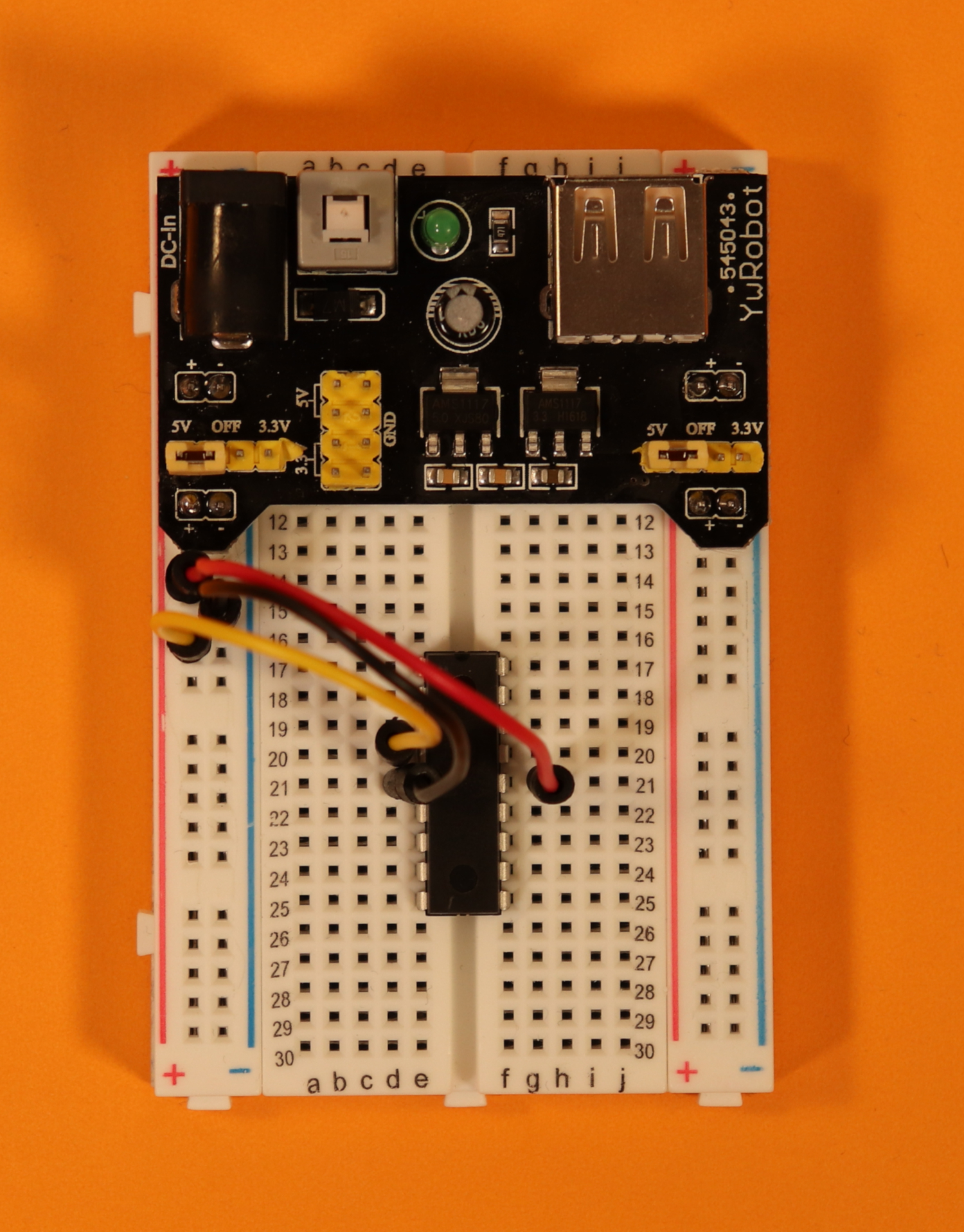
Step 6
Use a yellow cable to connect pin 4 (MCLR) of the PIC16F627A with the +5V power rail.
-
-
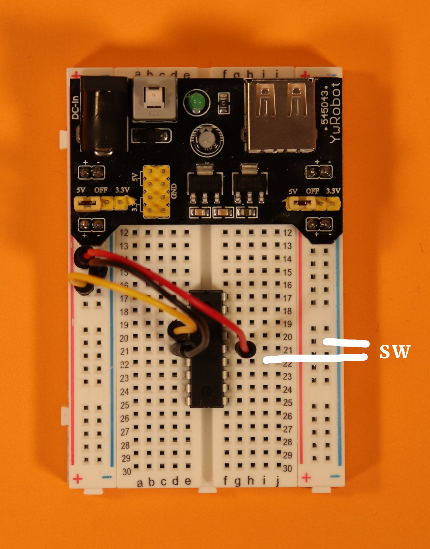
Step 7
Connect the pushbutton. Connect one of the leads to pin 13 of the PIC16F627A microcontroller, and connect the other lead to ground.
-
-
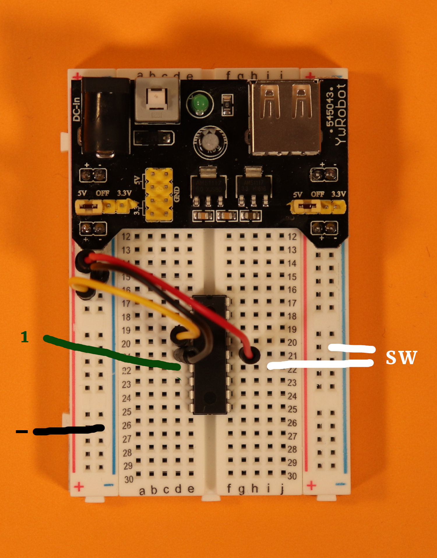
Step 8
Connect the LEDs one by one. The positive terminal (called simply “1” in the image) is connected to the PIC16F627A, and the negative terminal (labeled as “-”) is connected to ground.
In the picture you can see the connections for LED1.
-
-
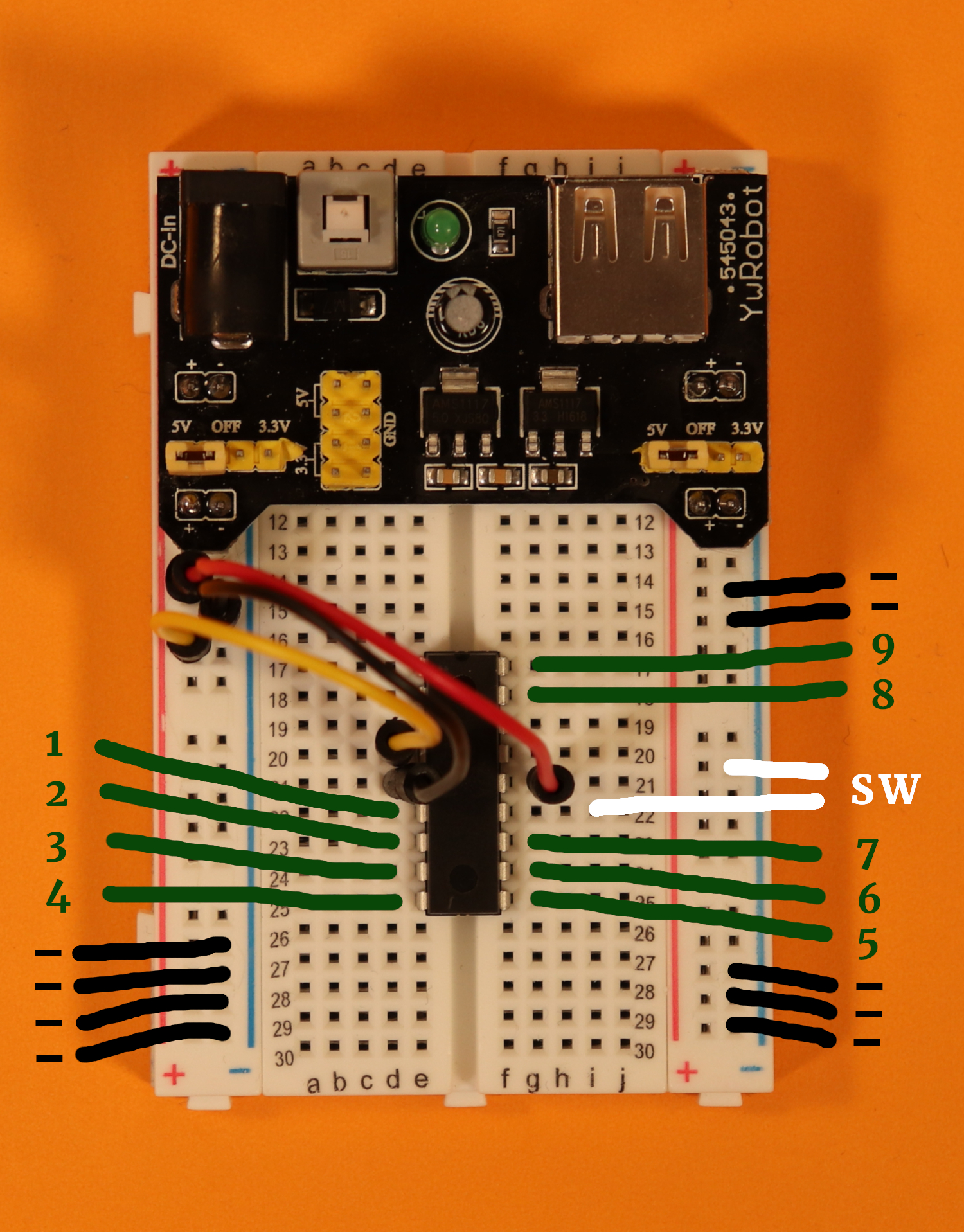
Step 9
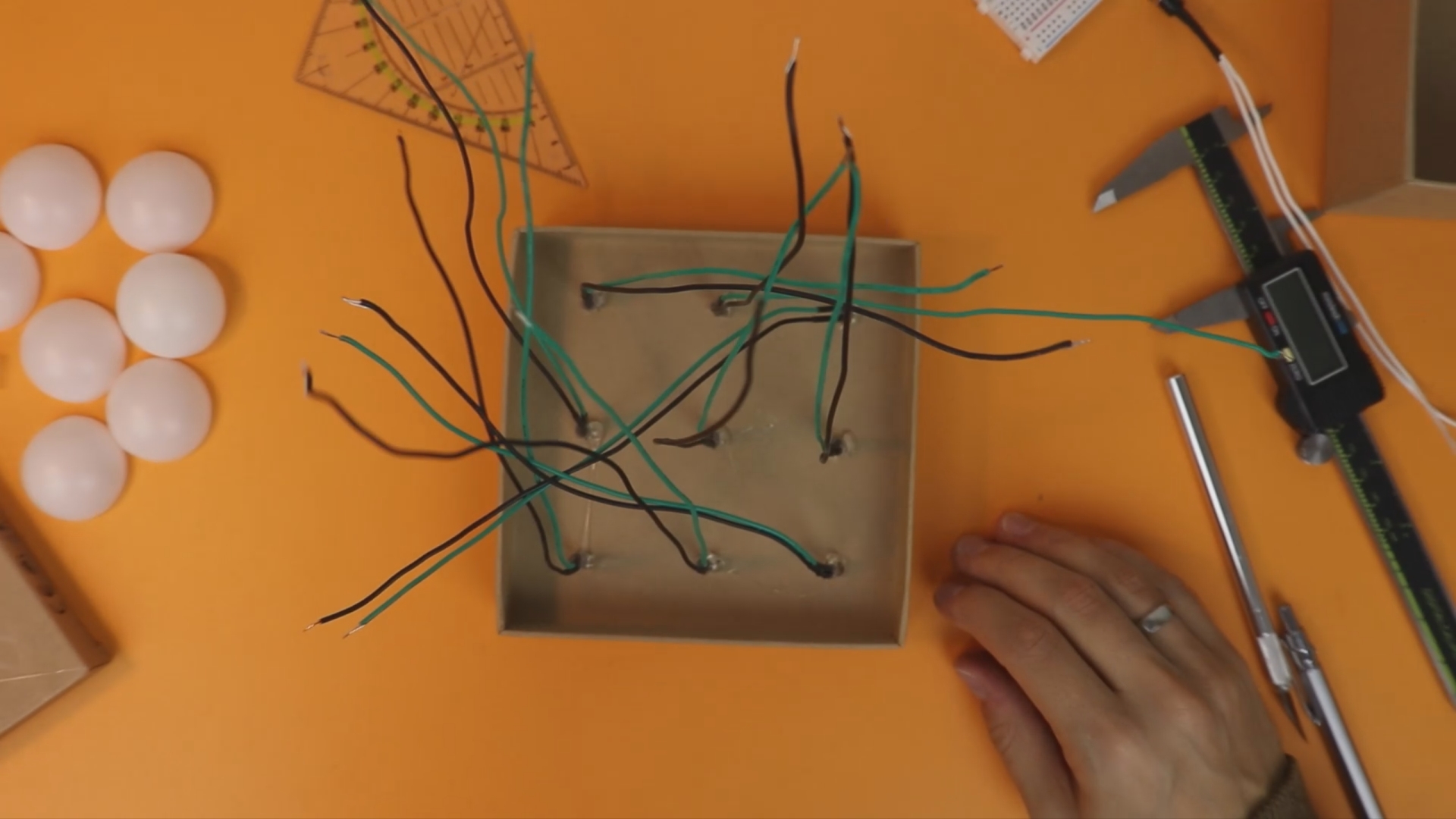
Connect LED2-LED9 in the same way as LED1. In the image to the left, the positive terminals for LED2 to LED9 are called “2” to “9” and the negative terminals are all called “-”. It can get a bit messy with all the cables, so it is a good idea to start with the positive terminals first.
Then, you can connect the ground wires anywhere on either side of the breadboard to the ground rails.
I hope this was helpful. If not, have a look at the YouTube video for a more three-dimensional explanation. If that still doesn't cut it for you, get in touch on social media, and we will figure it out :)
As a pushbutton you can use any standard pushbutton, see the components list. For LEDs I like to use ultrabright ones, see here:
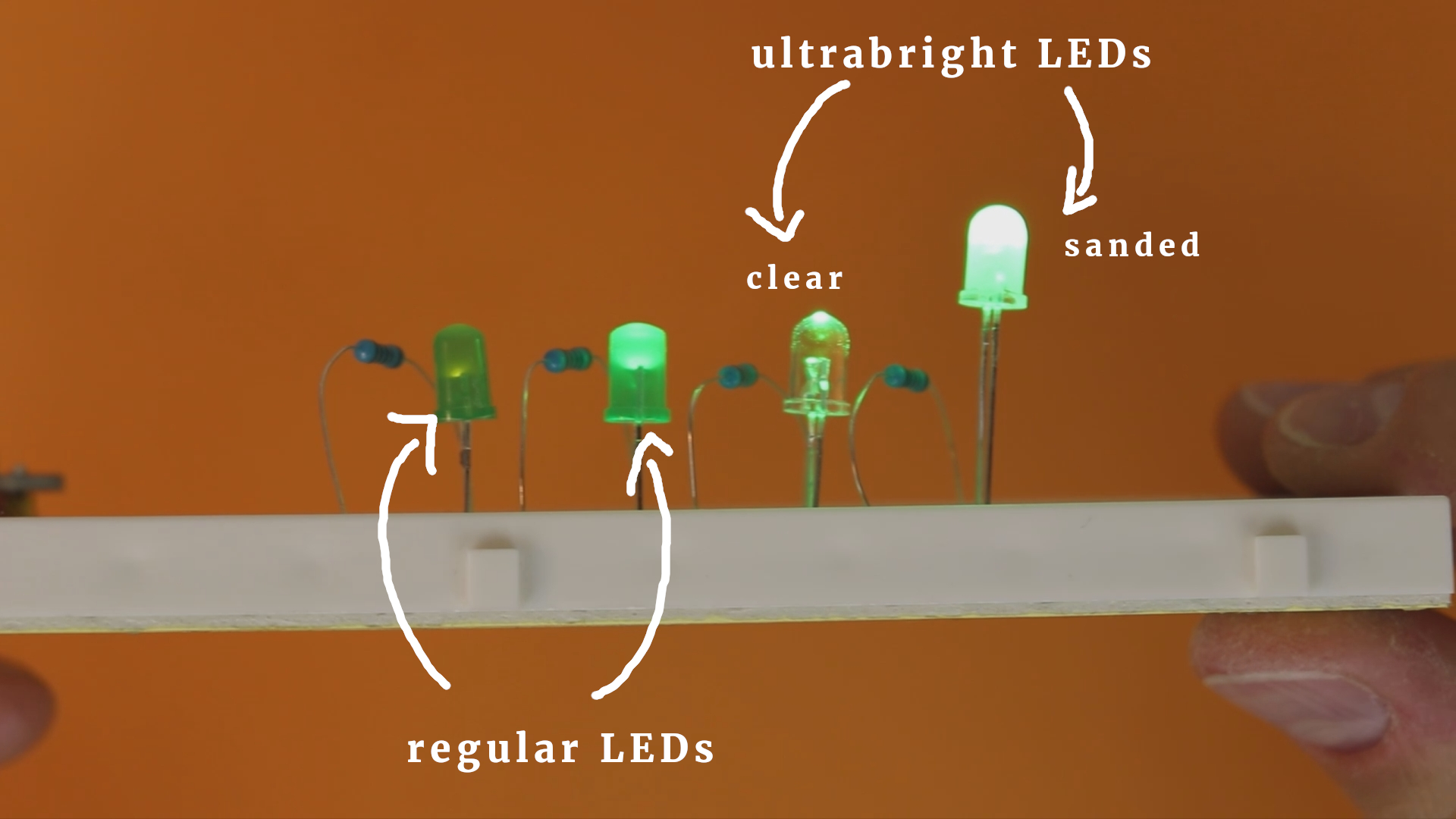
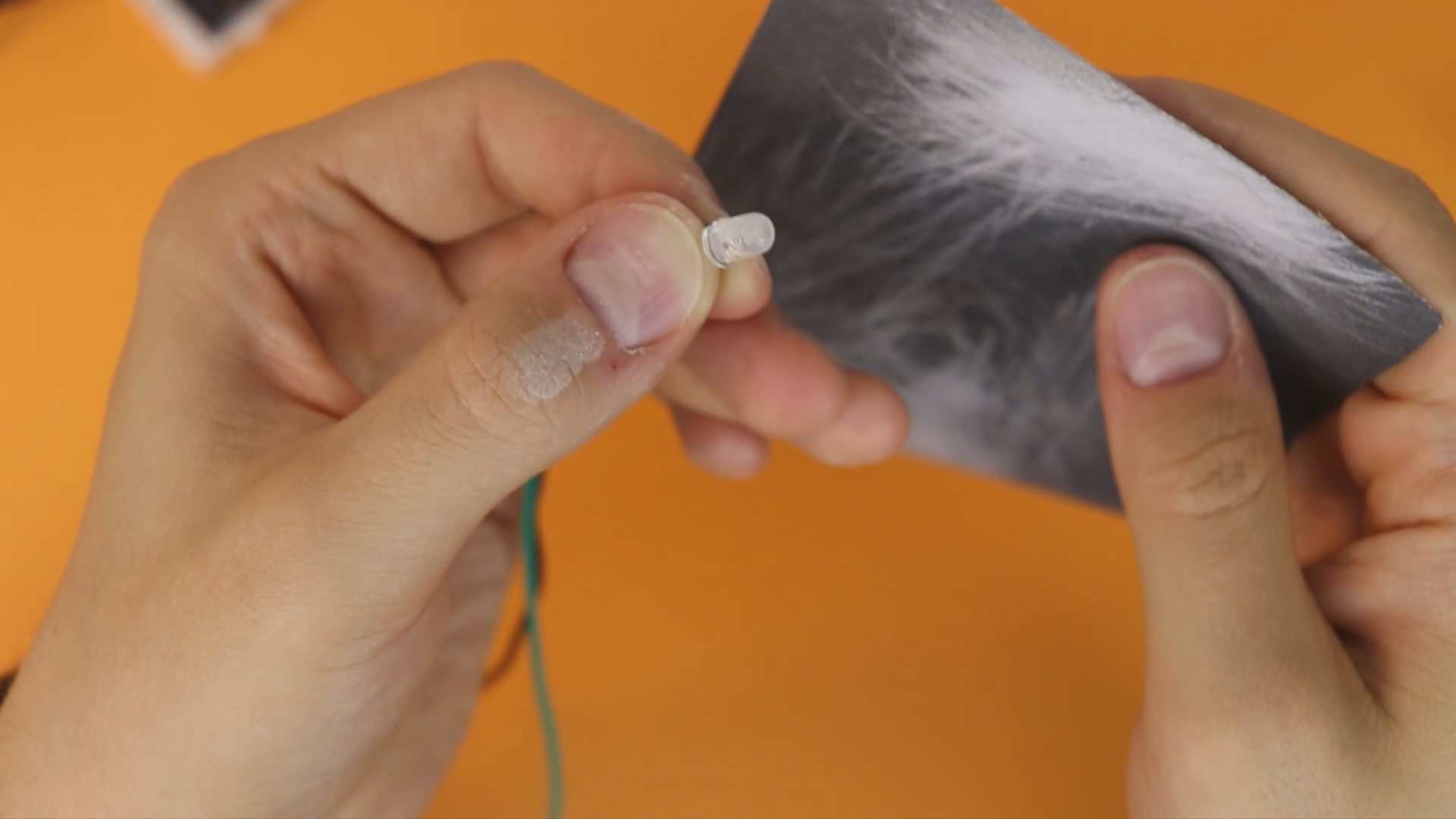
The right LED has been sanded using regular 400 grit sandpaper:
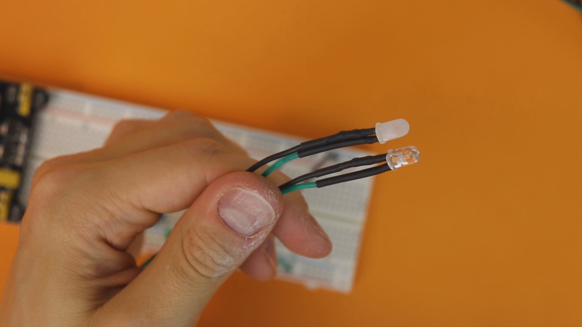

If you don't want to solder, you can find LEDs like these that are already pre-wired with a 220Ω resistor on Amazon or Ebay. Just make sure to get the 5 volts version and not the 9 volts or 12 volts version. They work, too, but the LEDs will be quite dim.
Assembling the housing
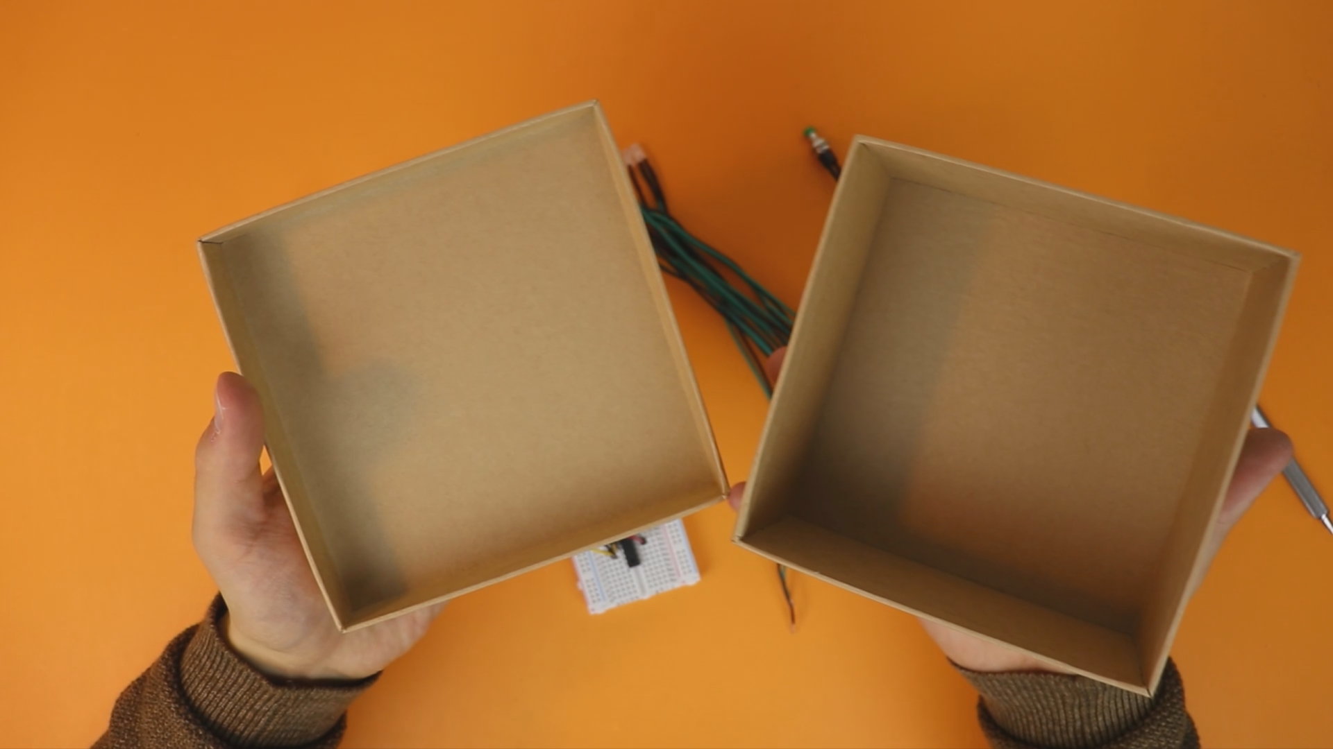
As a housing I use a simple cardboard box. These can be found in dollar stores and don't cost a lot, and they are just perfect for projects like this.
Our circuit does not get very hot because we use standard LEDs, so it is safe to use cardboard. If you want to use high-power LEDs then cardboard is a poor choice, of course.
As an extra diffuser for the LEDs we can use cheap ping pong balls that are easy to cut in half:

Make sure to follow the seam of the ping pong ball, it makes the cut a lot easier (and it helps to keep the cut straight, too).
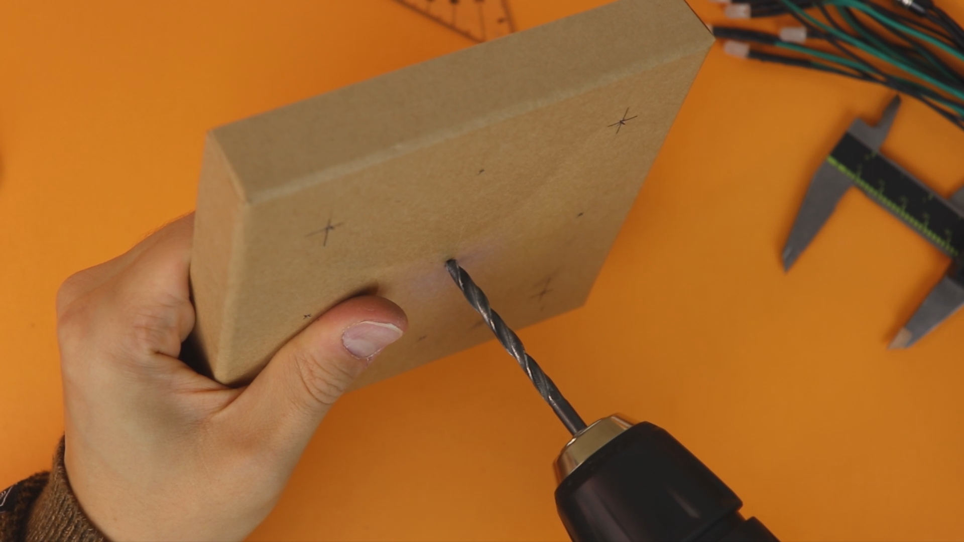
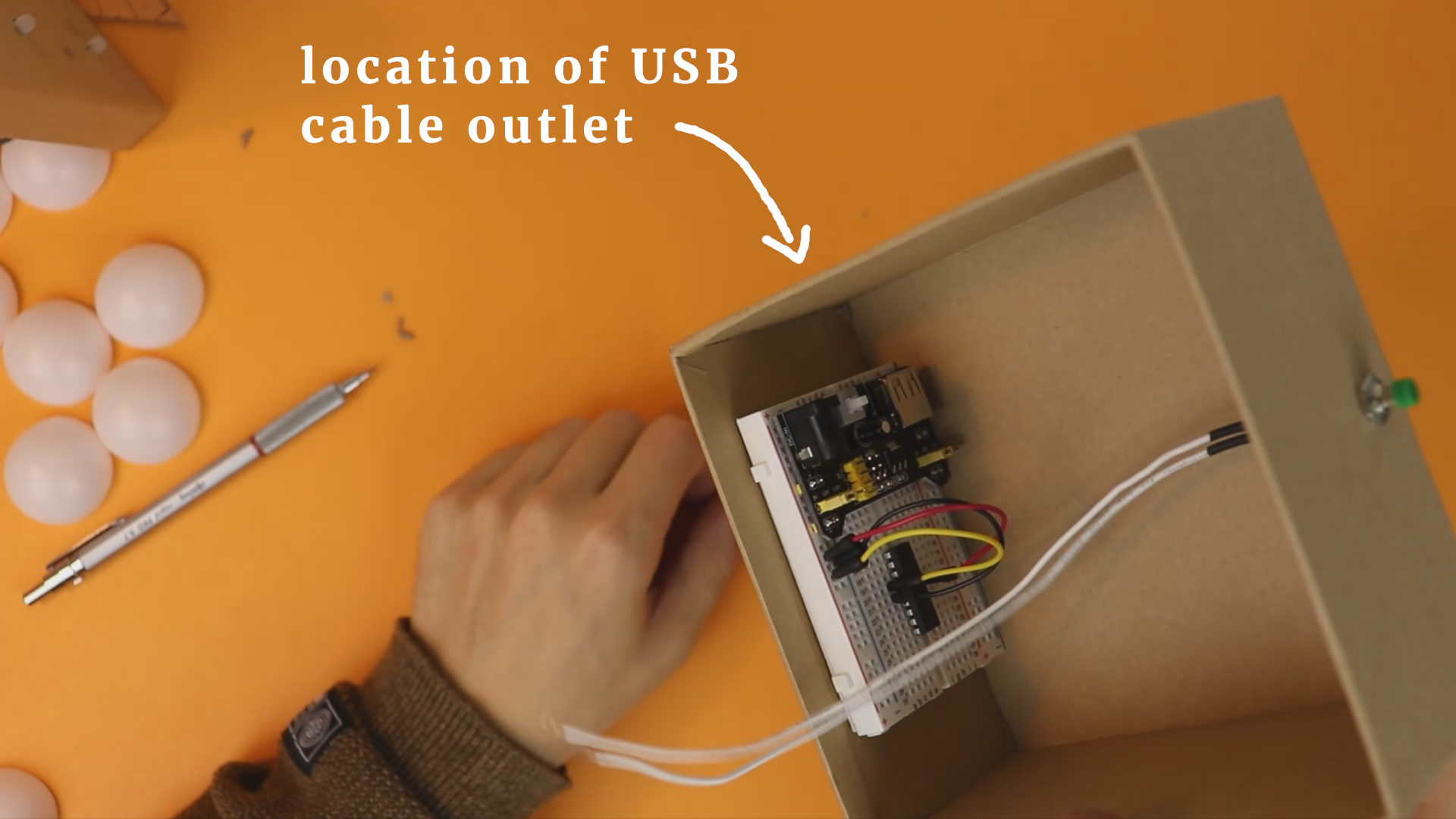
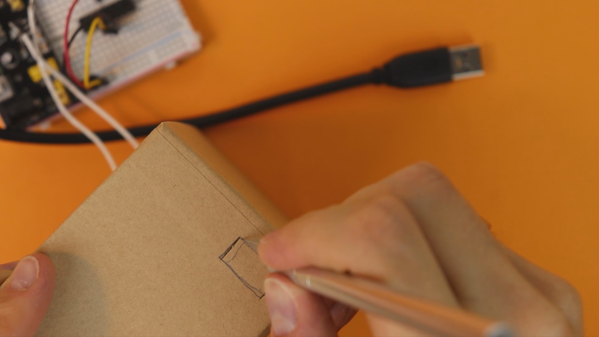
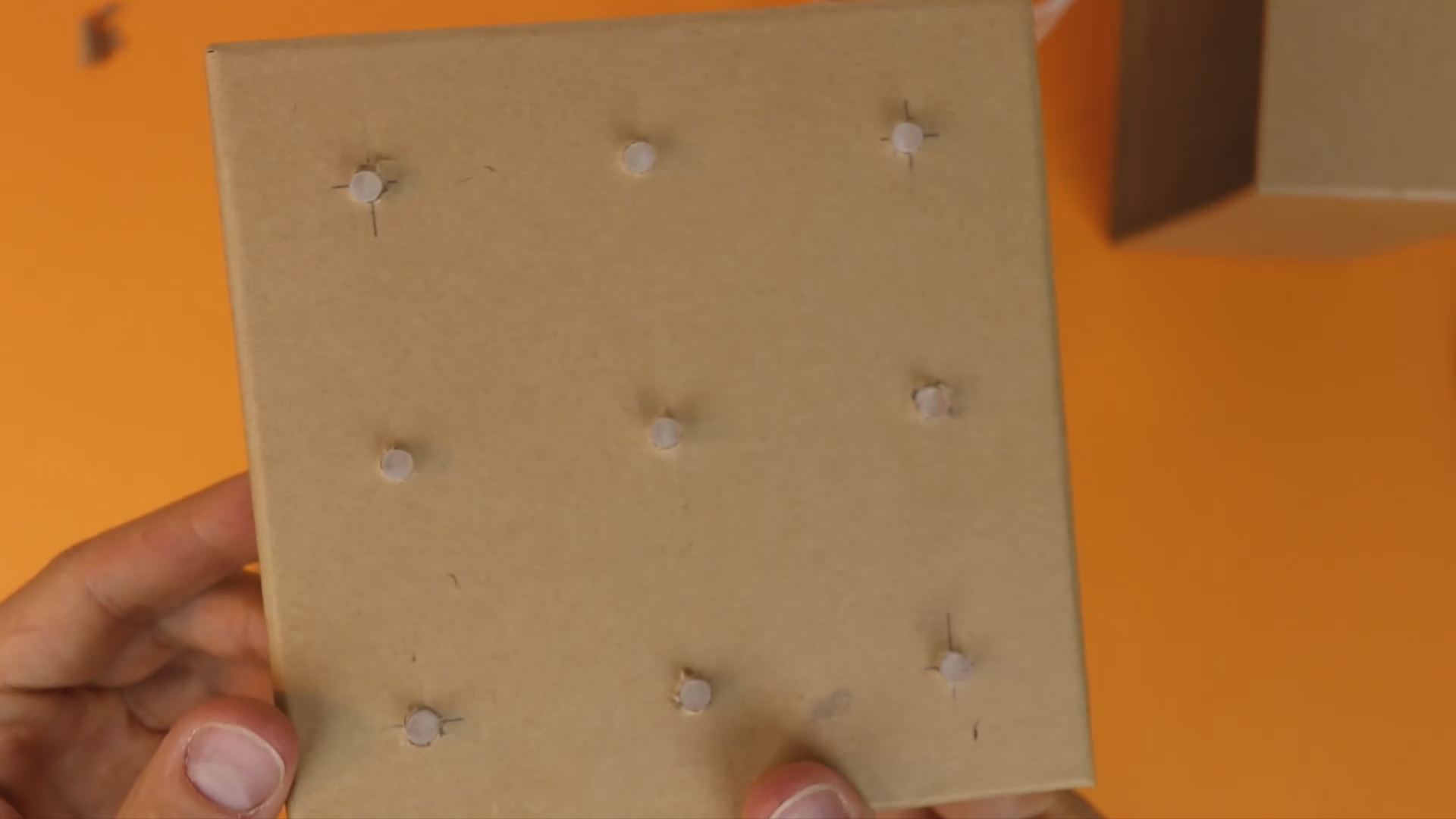
Next, we need to drill 5mm holes for the LEDs (here the caliper, the ruler, and the pencil are useful for marking the positions). We also need to cut an outlet for the USB cable that connects to the USB breadboard power supply, and we need to drill a hole for the pushbutton:

We can then glue the LEDs in place. The holes of 5mm in cardboard should hold them quite well, but I added some hot glue from the back just in case:
Next, we place the box with all the LEDs mounted in front of us, and we can attach the ping pong ball halfs using hot glue:

I found it the easiest to put two drops of hot glue on opposing sides. Then I just placed the half on the cardboard box and let gravity work its magic: because hot glue is liquid and takes a while to set, it will make contact with the cardboard after a few seconds. Make sure you don't move the ping pong ball when you place it, and after a minute or so it is rigidly attached.
And that's basically it! We are done!
Final thoughts
This project was a lot of fun for me, because it is a nice combination of everything we have learned so far. Also I think that this dice could actually be used at game nights with board games, so it is even useful (to some extent)! But kidding aside, if you understand the details of this project you can be proud of yourself, and you have made yet another step into a bigger world! That line might be borrowed from Qui-Gon Jinn, but it is still true!
I have to admit that I do not have a lot of experience in writing down instructions for projects. What did you like? What was good, what was bad? Please let me know :)
I hope I could show you that YOU can learn electronics! I have a few ideas for upcoming projects, but if you have a good idea, get in touch and tell me about it!
YouTube video
I covered this entire project in a dedicated YouTube video:
Appendix: full source code
Here is the full source code you can compile with the XC8 C compiler for PIC microcontrollers. You can also directly download the .hex file in the resources box of this article.
/*
 * File:   main.c
 * Author: boos
 *
 * Created on June 1, 2019, 12:26 PM
 */

#include <xc.h>

// BEGIN CONFIG
#pragma config FOSC = INTOSCIO
#pragma config WDTE = OFF
#pragma config PWRTE = OFF
#pragma config MCLRE = ON
#pragma config BOREN = OFF
#pragma config LVP = OFF
#pragma config CPD = OFF
#pragma config CP = OFF
//END CONFIG

// define ports for LEDs
#define LED1 RB0
#define LED2 RB1
#define LED3 RB2
#define LED4 RB3
#define LED5 RB4
#define LED6 RB5
#define LED7 RB6
#define LED8 RA0
#define LED9 RA1

// define port for switch
// (note the "!" which inverts the status, see below)
#define BUTTON !RB7

void main(void) {

  // enable weak pull-up resistors on PORTB
  nRBPU = 0;

  // all LEDs are outputs
  TRISB0 = 0;
  TRISB1 = 0;
  TRISB2 = 0;
  TRISB3 = 0;
  TRISB4 = 0;
  TRISB5 = 0;
  TRISB6 = 0;
  TRISA0 = 0;
  TRISA1 = 0;

  // the switch is an input
  TRISB7 = 1;

  // switch off comparator at port A
  CMCON = 0b111;

  // "counter" is the variable that stores the current
  // number that is displayed on the dice
  static unsigned char counter = 0;

  // this variable is used for the "slowing down" effect
  static int buffer = 0;

  // main loop
  while(1) {

    // when the button is pressed, keep advancing the dice number
    // (this happens really fast and makes the number "random")
    if (BUTTON) {
      counter++;
      if (counter > 11) {
          counter = 0;
      }
      buffer = 1500;

    // when the button is released, reduce the buffer variable
    // one by one. Whenever it passes 100 steps, advance the
    // dice number by one.
    } else {
        if (buffer > 0) {
            buffer--;
            if (buffer % 100 == 0) {
                counter++;
                if (counter > 11) {
                    counter = 0;
                }
            }
        }
    }

    // The following lines show the LED patterns that correspond
    // to a dice number. There are 12 variations because we also
    // include dice outcomes that are rotated by 90 degrees so that
    // there is a larger variety in outcomes.

    // 1
    if (counter == 0) {
        LED1 = 0;
        LED2 = 0;
        LED3 = 0;
        LED4 = 0;
        LED5 = 1;
        LED6 = 0;
        LED7 = 0;
        LED8 = 0;
        LED9 = 0;

    // 2
    } else if (counter == 1) {
        LED1 = 1;
        LED2 = 0;
        LED3 = 0;
        LED4 = 0;
        LED5 = 0;
        LED6 = 0;
        LED7 = 0;
        LED8 = 0;
        LED9 = 1;

    // 3
    } else if (counter == 2) {
        LED1 = 1;
        LED2 = 0;
        LED3 = 0;
        LED4 = 0;
        LED5 = 1;
        LED6 = 0;
        LED7 = 0;
        LED8 = 0;
        LED9 = 1;

    // 4
    } else if (counter == 3) {
        LED1 = 1;
        LED2 = 0;
        LED3 = 1;
        LED4 = 0;
        LED5 = 0;
        LED6 = 0;
        LED7 = 1;
        LED8 = 0;
        LED9 = 1;

    // 5
    } else if (counter == 4) {
        LED1 = 1;
        LED2 = 0;
        LED3 = 1;
        LED4 = 0;
        LED5 = 1;
        LED6 = 0;
        LED7 = 1;
        LED8 = 0;
        LED9 = 1;

    // 6
    } else if (counter == 5) {
        LED1 = 1;
        LED2 = 0;
        LED3 = 1;
        LED4 = 1;
        LED5 = 0;
        LED6 = 1;
        LED7 = 1;
        LED8 = 0;
        LED9 = 1;

    // 1
    } else if (counter == 6) {
        LED1 = 0;
        LED2 = 0;
        LED3 = 0;
        LED4 = 0;
        LED5 = 1;
        LED6 = 0;
        LED7 = 0;
        LED8 = 0;
        LED9 = 0;

    // 2
    } else if (counter == 7) {
        LED1 = 0;
        LED2 = 0;
        LED3 = 1;
        LED4 = 0;
        LED5 = 0;
        LED6 = 0;
        LED7 = 1;
        LED8 = 0;
        LED9 = 0;

    // 3
    } else if (counter == 8) {
        LED1 = 0;
        LED2 = 0;
        LED3 = 1;
        LED4 = 0;
        LED5 = 1;
        LED6 = 0;
        LED7 = 1;
        LED8 = 0;
        LED9 = 0;

    // 4
    } else if (counter == 9) {
        LED1 = 1;
        LED2 = 0;
        LED3 = 1;
        LED4 = 0;
        LED5 = 0;
        LED6 = 0;
        LED7 = 1;
        LED8 = 0;
        LED9 = 1;

    // 5
    } else if (counter == 10) {
        LED1 = 1;
        LED2 = 0;
        LED3 = 1;
        LED4 = 0;
        LED5 = 1;
        LED6 = 0;
        LED7 = 1;
        LED8 = 0;
        LED9 = 1;

    // 6
    } else if (counter == 11) {
        LED1 = 1;
        LED2 = 1;
        LED3 = 1;
        LED4 = 0;
        LED5 = 0;
        LED6 = 0;
        LED7 = 1;
        LED8 = 1;
        LED9 = 1;
    }

  }

  return;

}


