How to read out a pushbutton with a PIC microcontroller
May 24, 2019 • tutorial
In this week's post we will discuss the simple question of how to read-out the state of a pushbutton using a microcontroller. How can we check if a button is pushed down or not? What are common pitfalls?
You might say that this is not a particularly interesting project on its own, and I get that. But I am also convinced that breaking down a more complicated project in little digestible pieces is a great idea to develop a deep understanding of a topic. That way, later, in more complicated projects, we will be able to focus on the interesting stuff without getting side-tracked. So here we go!
What is a pushbutton?
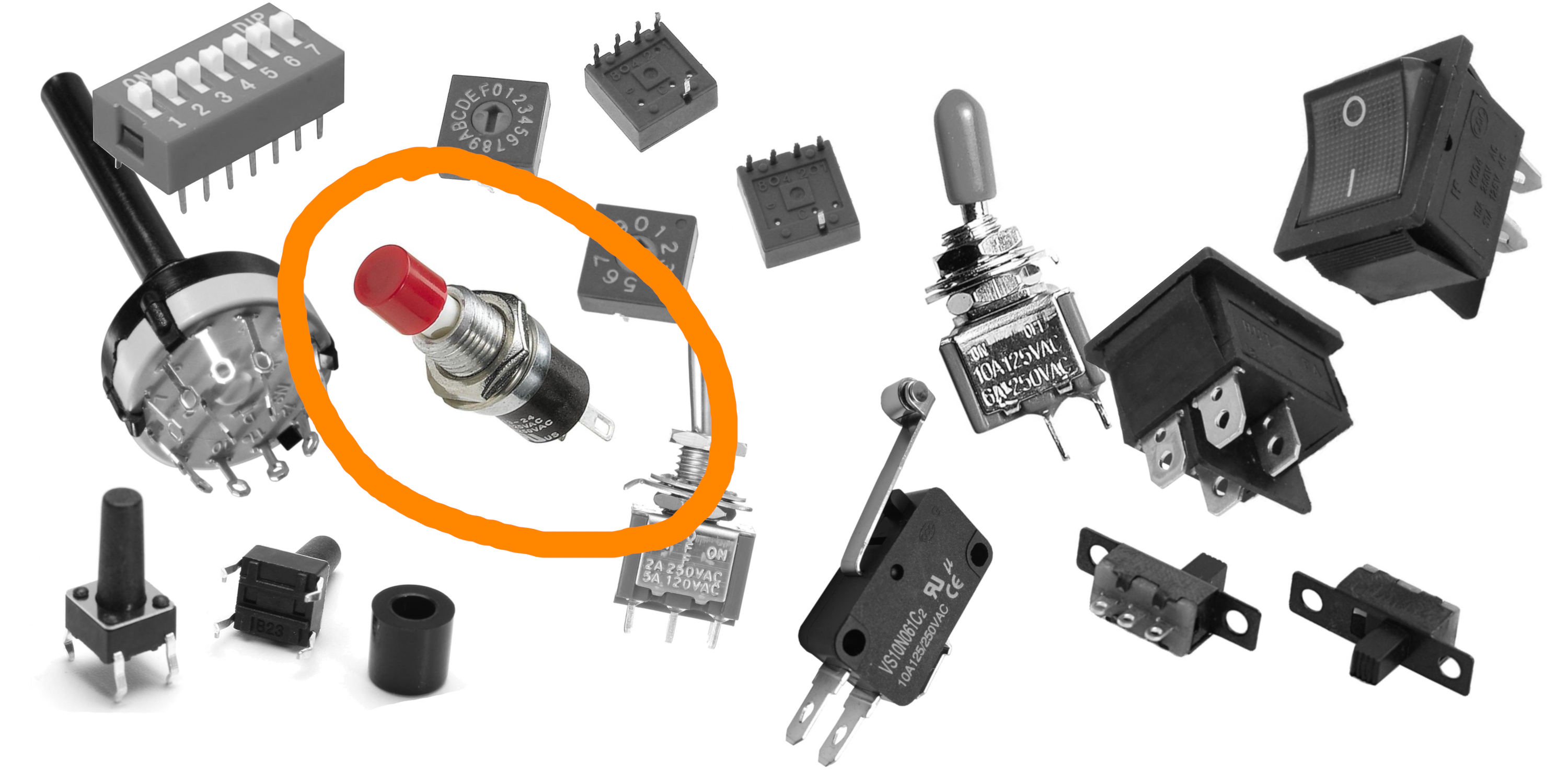
In last week's post we learned about the different kinds of buttons and switches, some of which you can see in the image above. Today, we will try to understand how to read out a pushbutton (circled in orange in the above image) with a microcontroller.
A pushbutton has only two states: it can be pressed, or it can be released. There are other switches that have more throws (for example, a rotary encoder) but we will leave that for another day. All we want: our microcontroller should notice when we press a button.
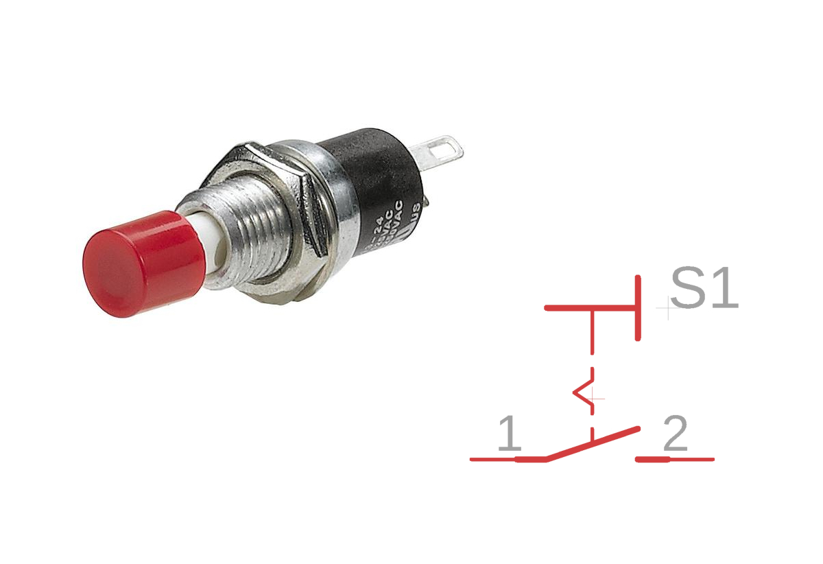
Here you can see the pushbutton we want to use with its schematic diagram:
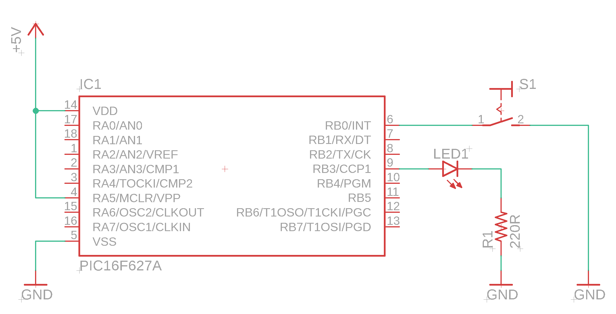
The schematic of our simple test circuit
To be concrete, let us take a look of the test circuit we want to build. Here it is:
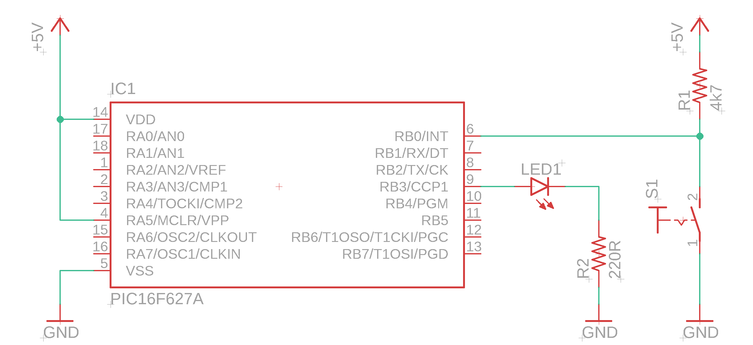
It is built around the PIC16F627A that we have already used in the led-blink tutorial, but the basics that we cover in this tutorial can be applied to any PIC microcontroller. So if you want to use a different controller you can keep reading :)
Let's go through the basics of the schematic, one step at a time:
- The supply symbols +5V and GND are not components, but just symbols. Anything connected to the +5V symbol must be connected to the positive terminal of the +5V power supply, and anything connected to the GND symbols must be connected to the ground terminal. It is sometimes more convenient to use several +5V and GND symbols because it saves us from drawing unnecessary extra lanes into the circuit diagram that makes it less readable. Let me know if you find this confusing, we can cover this topic in an upcoming post if you like :)
- With that out the way, let's focus on the more interesting stuff! :) The pin RB0 is connected to the pushbutton and to the 4.7kΩ resistor. If the button is pressed, pin RB0 is connected to ground. If the button is released, RB0 is connected to +5V over the resistor. More on that later.
- There is also an LED connected to port RB3, and this is exactly the same circuit we used in our led-blink tutorial a few weeks ago. We will use the LED to indicate the state of the pushbutton.
- It's important that the pin MCLR (master clear) is connected to +5V as well, because otherwise the PIC16F627A would keep resetting and would never run. We talked about the function of the MCLR pin in our pic-flash tutorial, go check it out if you want :)
Now we know what the schematic looks like. Let us now understand it as well!
Logic levels: quite literally the 101 of digital circuits

The two states of the pushbutton are discrete. What do I mean by that? There is nothing in between! Either its pushed, or it is released. There is no such thing as half-pushed. In electronics, such discrete states are also called logic levels.
Logic levels have two states, traditionally noted as 0 or 1. You can also think of them as OFF or ON, or LOW and HIGH. Digital circuits, such as microcontroller circuits, work almost exclusively with these kind of signals, and that explains the pun in the headline of this section.
The important message: +5V is called 1 or HIGH-level, and GND is called 0 or LOW-level.
Pull-up and pull-down resistors
Now that we know that microcontrollers work with logic levels, we understand why we need to insert the resistor R1 into the circuit!
Say, for a second, that we didn't do it. Then the schematic would look like this:
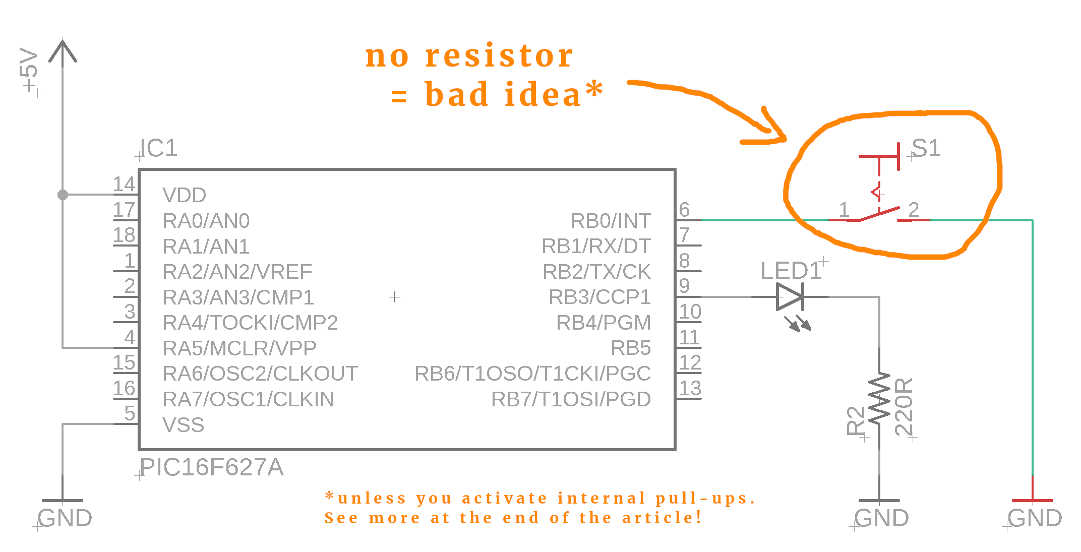
And sure enough, if you press the button, then the pin RB0 is on LOW (because it is connected to ground). But what if the button is left open? Well, then the inputs just floats around! And that is bad, because a floating input does not have a definite logic level which will confuse the microcontroller.
This is why we add the resistor R1 in the schematic:
When the button is open, the resistor R1 connects the pin RB0 to +5V. This is why we call it a pullup-resistor: it pulls the logic level up to HIGH.
Okay, but why do we need the resistor R1? you might ask. And it's true, if the button is open then the situation is exactly the same: pin RB0 would be connected directly to +5V.
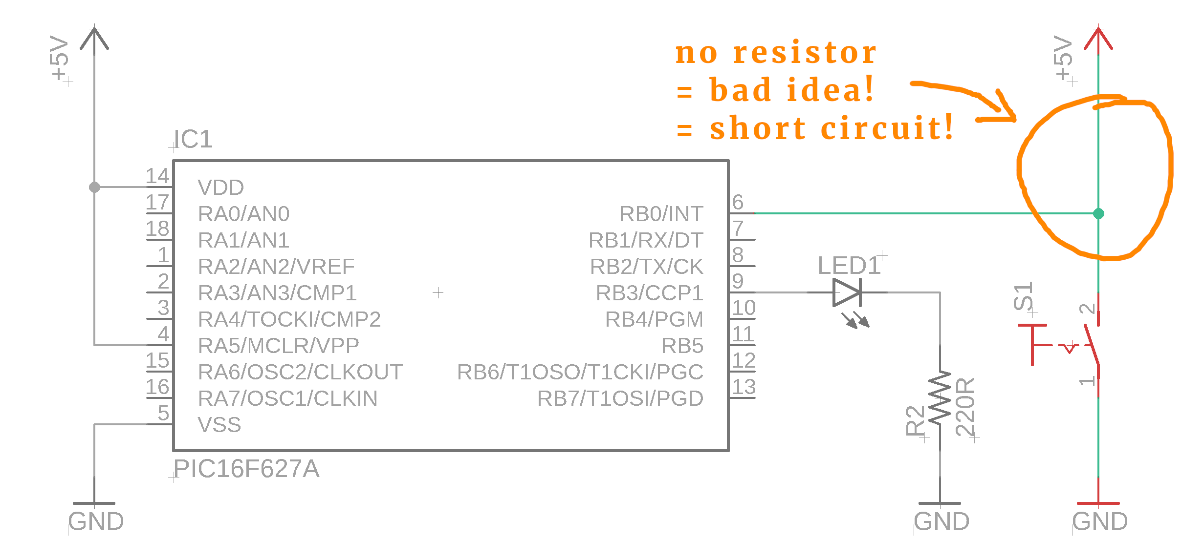
But what happens when you press the button? Then, +5V will be connected directly to GND, which is a short circuit! A short circuit is the death of any circuit, and we should avoid it at all cost. There is nothing that limits the current flowing from +5V to ground, leading to overheating and eventual death of the electronics. So, once again, here is the correct circuit, and I hope I could convince you that this makes sense:
The value of the pullup-resistor is not really critical. For 5V circuits the value of 4.7kΩ is frequently used, but you might as well use 10kΩ instead. Anything lower than 4.7kΩ is not a good idea because then the current flowing to the resistor would be unnecessarily high.
Lastly, you can of course also use a pull-down resistor. What is that? It is almost the same idea! The only difference is that pull-down resistors connect the input of the PIC to ground, and then you mount the switch between +5V and the input pin. It does not matter at all what option you choose. If you are curious: we choose the pull-up option in this tutorial because many PIC controllers have internal pull-up resistors that can be switched on automatically, so that we no longer need an external resistor. We will talk about this below.
A digital input for a PIC microcontroller
As we have seen in our first program some time ago, microcontrollers need to be programmed. The code tells them what to do. Microcontrollers have many pins that can be configured either as outputs or as inputs. In the led-blink tutorial we connected an LED to one pin RB3, configured it as an output, and made the connected LED blink.
Let us now tell the PIC16f627A to treat RB0 as an input. It is quite simple, we have to set the so-called tristate-register to the value 1:
TRISB0 = 1;Remember that in our first program, when we wanted a pin to be an output, we had to set the tristate register to 0 instead. Easy to remember:
- Configure a pint as an input: tristate register set to 1 (the “1” looks like the “I” in Input)
- Configure a pint as an output: tristate register set to 0 (the “0” looks like the “O” in Output)
Next, we can define an abbreviation for port RB0 to make our code a bit more user-readable:
#define SW RB0After this line, we can refer to RB0 as SW in the code (In my mind, “SW“ is an abbreviation for “switch,” but you can of course use any other abbreviation you want.)
Now we want to find out if the button is pressed. How do we do that? We need these lines:
if (!SW) {
	// do something
}
Do you notice the “!” sign? This inverts the result of reading out SW. If SW is 1, then !SW is 0, and if SW is 0, then !SW is 1. Sounds confusing, but all it does is switch a 0 for a 1 and a 1 for a 0.
We need to use the “!” because when the button is pressed the input will be LOW (because the button connects the input to ground). If we want to react instead to when the button is released, we write instead:
if (SW) {
	// do something
}
Finally, there is a nice way to capture both the pressed button and the released button. It works like this:
if (!SW) {
	// do something when the button is pressed
} else {
	// do something else when the button is released
}
The complete source code
Alright, here is the complete source code in all its glory:
/*
 * File:   main.c
 * Author: boos
 *
 * Created on May 23, 2019, 9:58 PM
 */

// CONFIG
#pragma config FOSC = INTOSCIO  // Oscillator Selection bits (INTOSC oscillator: I/O function on RA6/OSC2/CLKOUT pin, I/O function on RA7/OSC1/CLKIN)
#pragma config WDTE = OFF       // Watchdog Timer Enable bit (WDT disabled)
#pragma config PWRTE = OFF      // Power-up Timer Enable bit (PWRT disabled)
#pragma config MCLRE = ON       // RA5/MCLR/VPP Pin Function Select bit (RA5/MCLR/VPP pin function is MCLR)
#pragma config BOREN = ON       // Brown-out Detect Enable bit (BOD enabled)
#pragma config LVP = OFF        // Low-Voltage Programming Enable bit (RB4/PGM pin has digital I/O function, HV on MCLR must be used for programming)
#pragma config CPD = OFF        // Data EE Memory Code Protection bit (Data memory code protection off)
#pragma config CP = OFF         // Flash Program Memory Code Protection bit (Code protection off)

#include <xc.h>

#define SW RB0
#define LED RB3
#define _XTAL_FREQ 4000000

void main(void) {

	// RB0 is an input
	TRISB0 = 1;

	// RB3 is an output
	TRISB3 = 0;

	while (1) {

		if (!SW) {
			LED = 1;
		} else {
			LED = 0;
		}

	}

	return;
}
Debouncing: what is it, and why should you care?
So far, all our program does is to directly display the state of a pushbutton via the LED. Press the button, the LED glows. Release the button, and the LED goes off. That is not a very realistic application.
Usually, pushbuttons are used to transmit some information into the controller. When you set the time on your microwave, and it is 9am, you have to press the hours button nine times, to advance the hours from 12am to 9am.
Let's consider the following schematic (this time with a pull-down resistor instead of a pull-up resistor, just for fun):
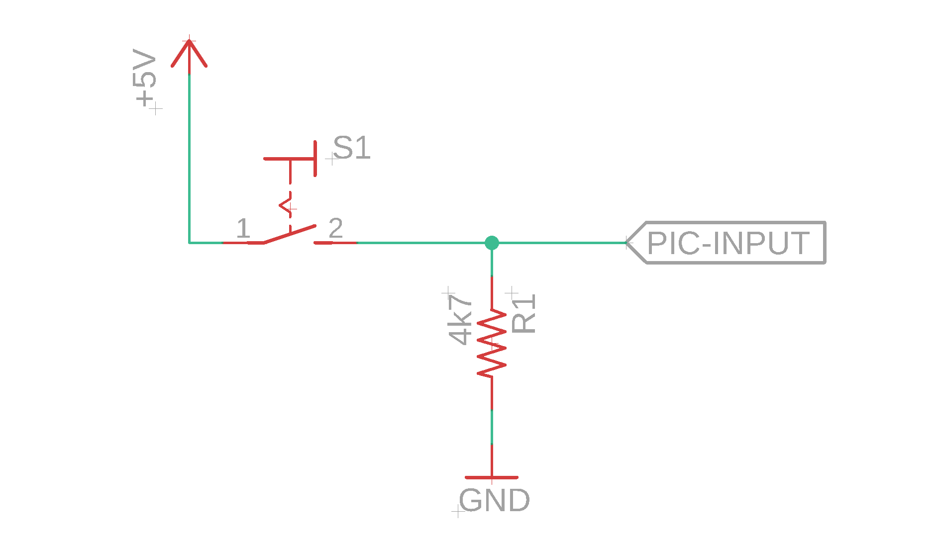
When you press the button S1, the PIC-INPUT gets connected with +5V. Otherwise, it is connected to GND via the pull-down resistor. Imagine now that you press the button in real life, hold it down, and monitor the signal at the PIC-INPUT label really closely. You will see something like this:

The green line is the signal or the logic level. We see that when you press the button, it jumps around! This is called bouncing, and it happens because the mechanical switch inside the button vibrates when the button is pressed down. It is a very fast process and only lasts around 0.5-1 milliseconds. Not all buttons exhibit bouncing, but most of them do. It is invisible to the human eye, but our fast electronics circuits get confused by it.
It is a real concern: think again about your microwave. When you press the button just once (as in the above plot), you want to advance the hours from 1pm to, say, 2pm. But what will happen? Looking at the above diagram, you see that a single button press actually gets registered as more than one, in this case as three button presses!
Counteracting this bouncing is called debouncing, who would have thought :) There are many ways this can be done, and there are two excellent articles on this topic over at All About Circuits and The Lab Book Pages.
In this tutorial, we will focus on the question of how to debounce a switch using software.
Debouncing in software
Actually, debouncing in software is is quite simple. But let's not get ahead of ourselves. First, we need to modify the program a bit so that the whole debouncing thing becomes necessary in the first place.
The above software merely mirrors the state of the button onto the LED. If the button is pressed, the LED is illuminated. If the button is left released, the LED is off. So even if there is bouncing, we would never see it: the LED would just blink really quickly and then stay off after the we release the button and the bouncing is complete.
So I wrote a different program. It does the following:
- At the beginning, the LED is turned off.
- Each button press then toggles the state of the LED.
Think about it for a second. It is a slightly different program from before, and now we really need the debouncing.
Okay, but how do we implement it? It is very simple :) The key observation is that the bouncing happens very quickly, so we just need to ignore very rapid button changes! How do we tell our PIC to do that?
Here is the relevant code (full code below):
while (1) {

		// toggle the status
		// (but only when the button is pressed
		//  AND when enough time has passed since the last button press )
		if ((!SW) && (SW_debounce == 0)) {
			status = !status;
		}

		// if the button is active, set the buffer
		if (!SW) {
			SW_debounce = 100;
		}

		// drive the LED
		if (status) {
			LED = 1;
		} else {
			LED = 0;
		}

		// debouncing
		if (SW_debounce > 0) {
			SW_debounce--;
		}

	}
Let's go through the lines and explain the main idea!
- Lines 1 and 27 comprise the main loop that gets run over and over again.
- Lines 3-8 react to the button press. The variable
statuscontains the state of the LED. The expressionstatus = !status;inverts the value of the variable, which is what we want the button press to do, nothing special. - Line 15-20 are pretty standard and just map the content of the
statusvariable onto the LED. - Lines 11-13 are important for the debouncing. Remember that at the beginning the buffer variable
SW_debouncehas the value zero. Whenever the button gets pressed, though, it gets set to 100. Then, a second button press (from bouncing) will not be registered by the software because the second condition in line 6 (SW_debounce == 0) is no longer met. - If it weren't for lines 22-25, we would arrive in a deadlock because we could never toggle the LED ever again. Remember that the internal frequency of operation is 4MHz which corresponds to about one million instructions per second (you have to divide by four for technical reasons). Each time the main loop cycles through, at the end, we subtract 1 from the buffer variable
SW_debounce. After one hundred cycles, the buffer variable is back to zero, and the software can react to a button press again. - By the time the software can react again, we hope that the button bouncing phase is over already. This way we can teach the controller to ignore the bouncing. The number 100 is chosen by trial-and-error. When you work with switches, just play with this number a bit. It depends on your switch (some of them have a ridiculously long bounce time) as well as the operating speed. If you run your program at a low frequency of a few kHz, the value 100 could turn your software blind to button presses for a couple of seconds!
Let me know if this explanation is clear for you. If it is not clear to you I will do my best to explain it better next time :) Here is the complete code:
/*
 * File:   main.c
 * Author: boos
 *
 * Created on May 23, 2019, 10:13 PM
 */

// CONFIG
#pragma config FOSC = INTOSCIO  // Oscillator Selection bits (INTOSC oscillator: I/O function on RA6/OSC2/CLKOUT pin, I/O function on RA7/OSC1/CLKIN)
#pragma config WDTE = OFF       // Watchdog Timer Enable bit (WDT disabled)
#pragma config PWRTE = OFF      // Power-up Timer Enable bit (PWRT disabled)
#pragma config MCLRE = ON       // RA5/MCLR/VPP Pin Function Select bit (RA5/MCLR/VPP pin function is MCLR)
#pragma config BOREN = ON       // Brown-out Detect Enable bit (BOD enabled)
#pragma config LVP = OFF        // Low-Voltage Programming Enable bit (RB4/PGM pin has digital I/O function, HV on MCLR must be used for programming)
#pragma config CPD = OFF        // Data EE Memory Code Protection bit (Data memory code protection off)
#pragma config CP = OFF         // Flash Program Memory Code Protection bit (Code protection off)

#include <xc.h>

#define SW RB0
#define LED RB3
#define _XTAL_FREQ 4000000

void main(void) {

	// RB0 is an input
	TRISB0 = 1;

	// RB3 is an output
	TRISB3 = 0;

	// status variable that we want to toggle with a button press
	int status = 0;

	// auxiliary debouncing variable
	int SW_debounce = 0;

	while (1) {

		// toggle the status
		// (but only when the button is pressed
		//  AND when enough time has passed since the last button press )
		if ((!SW) && (SW_debounce == 0)) {
			status = !status;
		}

		// if the button is active, set the buffer
		if (!SW) {
			SW_debounce = 100;
		}

		// drive the LED
		if (status) {
			LED = 1;
		} else {
			LED = 0;
		}

		// debouncing
		if (SW_debounce > 0) {
			SW_debounce--;
		}

	}

	return;
}
Use internal pull-up resistors
Many PIC microcontrollers offer internal pull-up resistors. They can be switched on or off by setting a certain bit in software. For the PIC16F627A they are switched ON like this:
nRBPU = 0;Yes, that switches them ON. Why do we need to set it to zero to switch them ON? This is a technicality, but you can tell from the name of the configuration bit. It is not RBPU but rather nRBPU, where the “n” stands for “negated.”
And, while speaking of acronyms, RBPU stands for Port B Pull-Up. Notice how we didn't specify for which input pin we enabled the pull-ups! This is because RBPU enables a pull-up on every input pin on PORT B (PORT B is the collection of all the pins RB0, RB1, RB2, RB3, RB4, RB5, RB6, RB7).
But wait, doesn't this mess with our LED at port RB3? you might wonder. No, RBPU only affects those pins that are configured as inputs. Since we configured the pin RB3 as an output, it remains unaffected.
This is quite nifty because we can now omit the pull-up resistor. The final, optimized schematic looks like this:
I listed the final source code that sets the internal pull-ups and that comes with software-debouncing in the appendix. The above circuit is the most ideal one we can build with the PIC16F627A because it uses the least amount of external components, and in the future we will see this kind of circuit countless times :)
Now what?

Congrats, you have made it! I hope I could explain how to connect a button and how to read it out using a microcontroller. If anything was unclear, please do let me know, and I will do my best to improve the presentation :)
We are finally ready to leave the stage of tutorials and are now fully equipped to start thinking about real projects! Let me know if you have any ideas or suggestions. Thanks for reading!
Appendix: Software debouncing with internal pull-ups enabled
/*
 * File:   main.c
 * Author: boos
 *
 * Created on May 24, 2019, 12:05 AM
 */

// CONFIG
#pragma config FOSC = INTOSCIO  // Oscillator Selection bits (INTOSC oscillator: I/O function on RA6/OSC2/CLKOUT pin, I/O function on RA7/OSC1/CLKIN)
#pragma config WDTE = OFF       // Watchdog Timer Enable bit (WDT disabled)
#pragma config PWRTE = OFF      // Power-up Timer Enable bit (PWRT disabled)
#pragma config MCLRE = ON       // RA5/MCLR/VPP Pin Function Select bit (RA5/MCLR/VPP pin function is MCLR)
#pragma config BOREN = ON       // Brown-out Detect Enable bit (BOD enabled)
#pragma config LVP = OFF        // Low-Voltage Programming Enable bit (RB4/PGM pin has digital I/O function, HV on MCLR must be used for programming)
#pragma config CPD = OFF        // Data EE Memory Code Protection bit (Data memory code protection off)
#pragma config CP = OFF         // Flash Program Memory Code Protection bit (Code protection off)

#include <xc.h>

#define SW RB0
#define LED RB3
#define _XTAL_FREQ 4000000

void main(void) {

	// enable pull-ups on PORTB
	// (Yes, we have to set it to zero to enable it, because this configuration bit is inverted.
	//  You can tell so by the preceding "n" in front of the "RBPU")
	nRBPU = 0;

	// RB0 is an input
	TRISB0 = 1;

	// RB3 is an output
	TRISB3 = 0;

	// status variable that we want to toggle with a button press
	int status = 0;

	// auxiliary debouncing variable
	int SW_debounce = 0;

	while (1) {

		// toggle the status
		// (but only when the button is pressed
		//  AND when enough time has passed since the last button press )
		if ((!SW) && (SW_debounce == 0)) {
			status = !status;
		}

		// if the button is active, set the buffer
		if (!SW) {
			SW_debounce = 100;
		}

		// drive the LED
		if (status) {
			LED = 1;
		} else {
			LED = 0;
		}

		// debouncing
		if (SW_debounce > 0) {
			SW_debounce--;
		}

	}

	return;
}


