Schematics 101 – how to read them and not get overwhelmed
May 31, 2019 • tutorial
Whenever you build an electronics project that surpasses a certain complexity, a schematic is needed. Schematics show all the components in an electric or electronic circuit, and how these components are connected to each other. At the same time, they can be quite hard to understand and it is easy to get overwhelmed.
In this tutorial we will go through the basics of schematics, and I will list a few helpful strategies to understand even complicated schematics. So, if you are new in electronics and sometimes get intimidated by schematics, look no further :)
And, as always: if anything is not clear, get in touch on social media and I will do my best to help!
Just as a small disclaimer: in this article I will talk about schematics generated with Eagle which we talked about earlier in an article on useful software in hobby electronics. Many of the details we address work for schematics in general, so even if you don't use Eagle I hope that this tutorial will be ever so slightly useful :)
What is a circuit? What is a schematic?
In understanding schematics, I find it helpful to understand the difference between a circuit and a schematic.
- The circuit is the real thing that we build, on a breadboard, with wires, cables, and tools, right in front of us.
- The schematic is an abstraction of that circuit, a mere representation. It is not real.
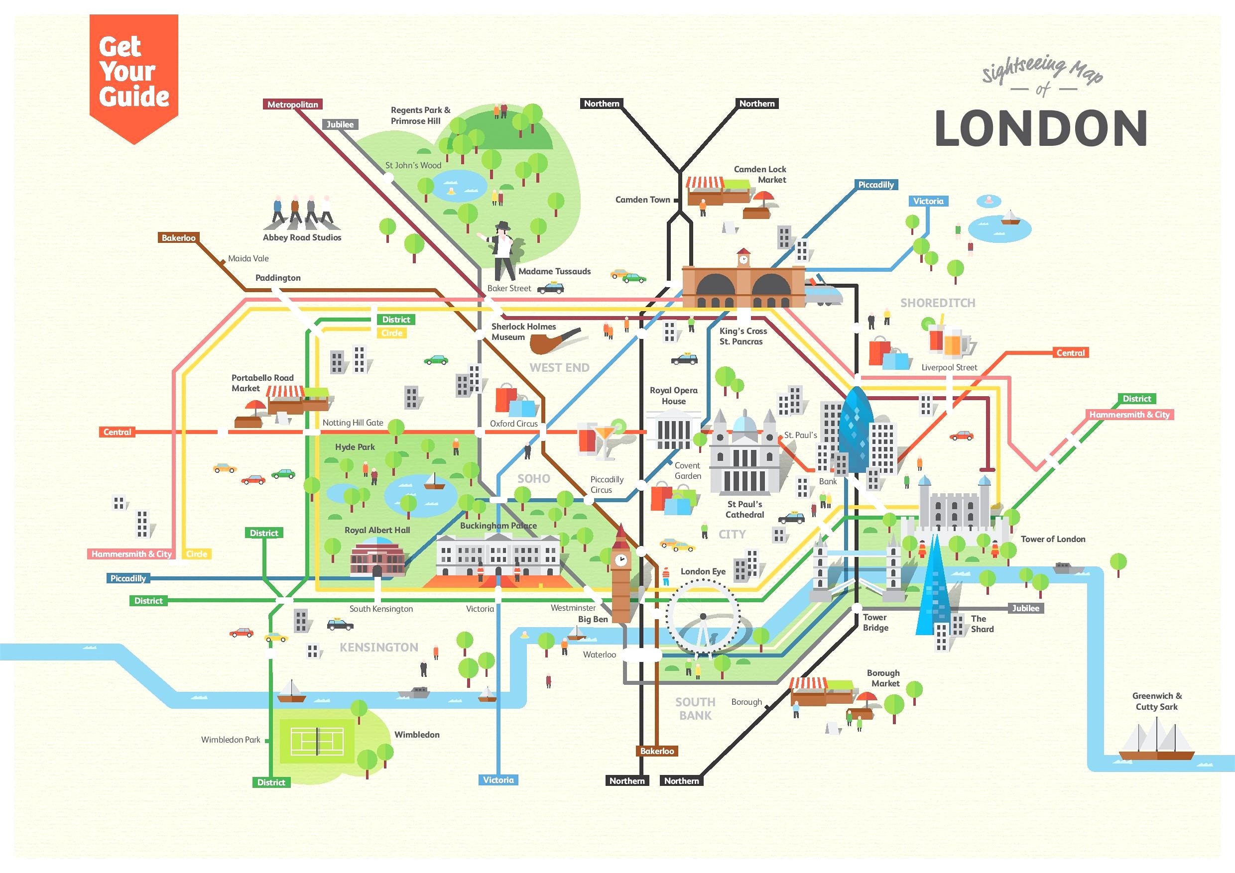
Okay, some of you might think I've kind of lost it. So let me give you an example of what I mean. Let's look at these two pictures of London:

|
|
The first one is an accurate satellite image of London. The second one is the map of the London tube. In our example, the first one is the circuit (the “real thing”) and the second one is the schematic (the “abstraction”). I hope it makes more sense now.
A schematic only cares about what is connected to what. Much like the map of the London tube: if you want to get from the Sherlock Holmes Museum to Piccadilly Circus, you don't need to know all the detailed directions en route there. It is enough to know that you can take the Bakerloo Line for two stops.
All of this is to say that a schematic does not necessarily have to resemble the actual circuit in shape or form :)
Supply symbols
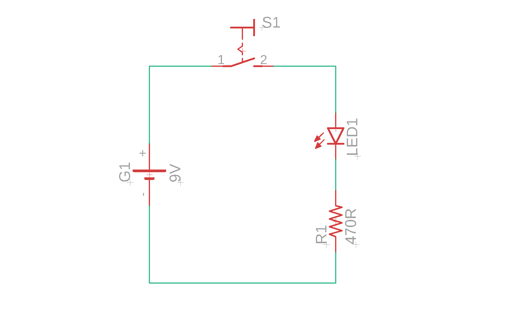
Okay, let's talk about something else. When I first looked at schematics, I found the so-called supply symbols to be very confusing. Let's illustrate that with a simple example. Think about an LED (and her resistor) that is connected to a battery using a switch. This is the schematic:
Pretty simple, right? The following schematic is an equivalent way to depict the same thing:

It looks very different, doesn't it? There are two supply symbols that are the reason for this difference:
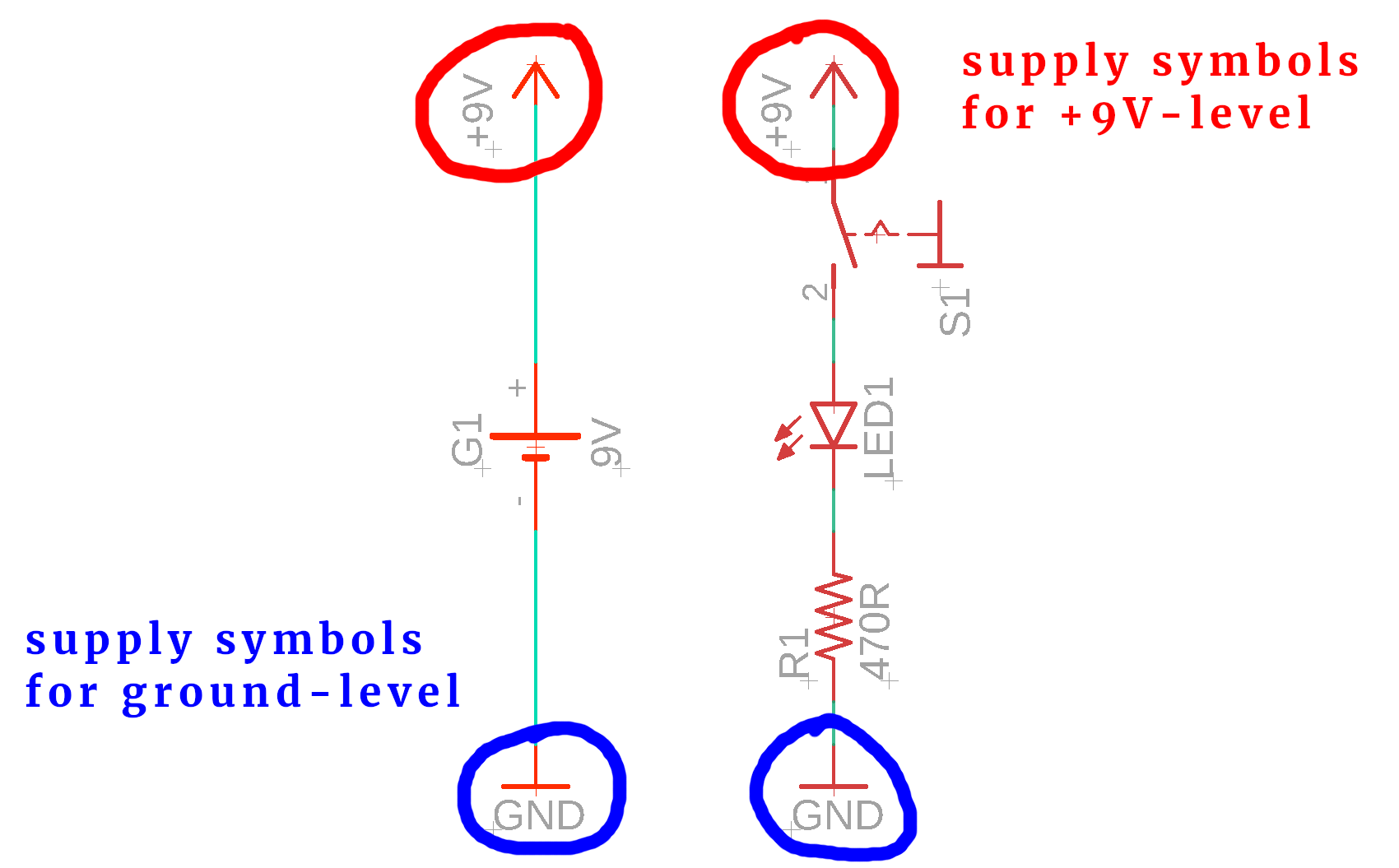
Basically, the supply symbols are sort of a collective symbol. Anything connected to the same supply symbol is automatically connected to each other. The one side of the resistor is connected to the GND supply symbol, as is the negative terminal of the battery. Therefore, the negative terminal of the battery is also connected to the one end of the resistor. Makes sense?
This is very similar to breadboards! On breadboards we already find these kind supply symbols, but we usually call them “rails:”
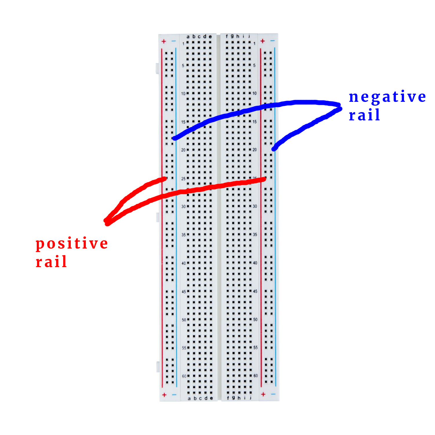
In the above example there are only two rails. In practice, there can be many many more. Often, circuits have a +12V rail and a +5V rail (or a +3.3V rail). Sometimes, they have a negative voltage rail. But now that we know what they are we can understand them!
Power supply for ICs
Integrated Circuits (or “ICs” or short) are ubiquitous in electronics. Unfortunately their power supply can be depicted in a rather confusing way.
Here is the PIC16F627A microcontroller that we have seen many times (and, for simplicity, it is only connected to the operating voltage):

This, on the other hand, is a standard digital counting IC (we don't actually need to know what it does, for our intents and purposes it is just “some other IC”):
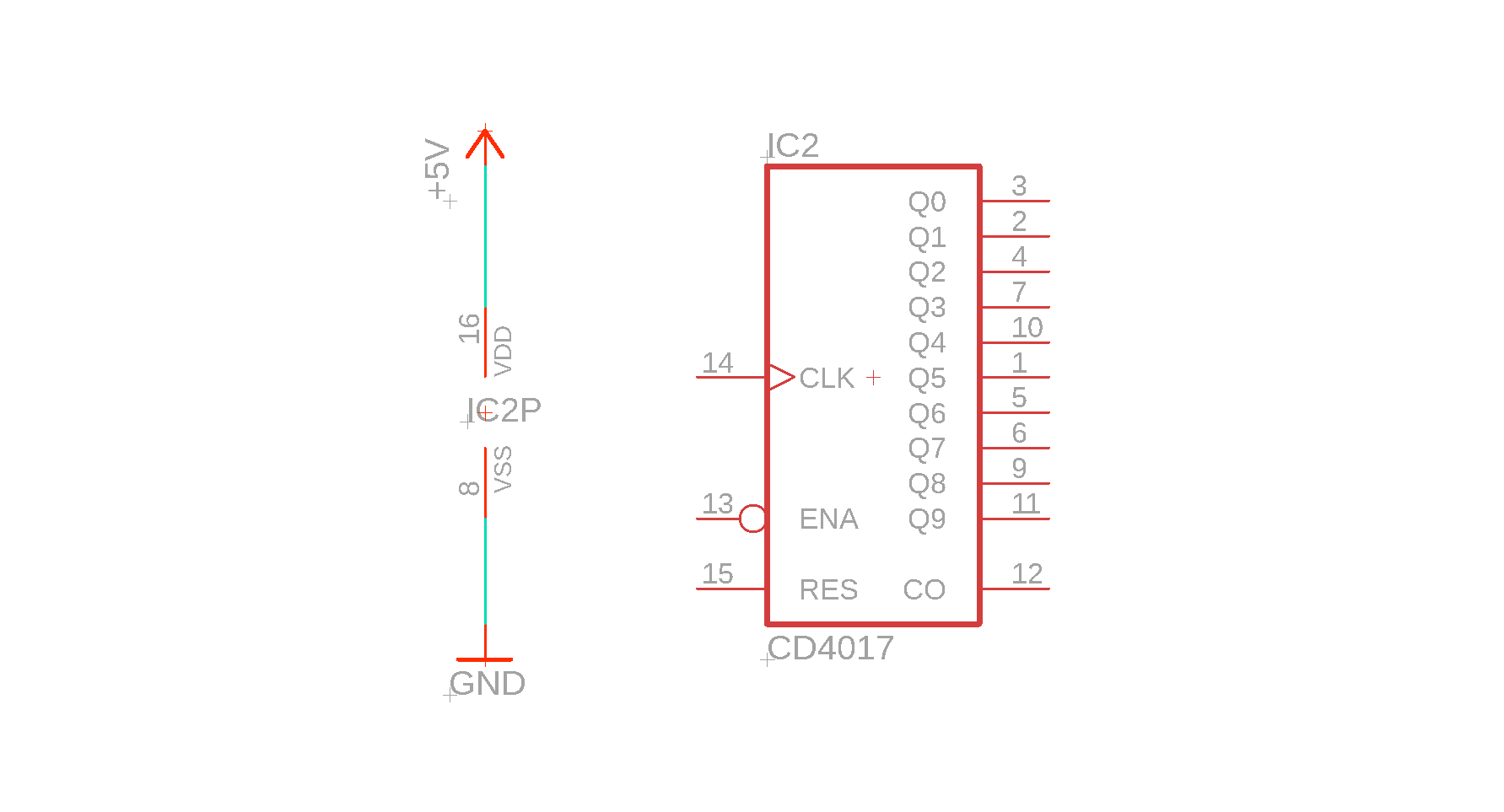
Do you see the difference? The PIC16F627A's symbol has dedicated pins for power supply. The CD4017's power supply pins (pin 8 for GND and pin 16 for +5V), however, appear as a separate component, labeled IC2P. This undoubtedly must stand for IC2 Power supply.
But why is it a separate symbol?
Quite frankly, I don't know. I have one theory: Usually, there are a lot of these types of ICs (so-called logic ICs, like the CD4017, and many of its friends and colleagues) in one circuit. They are rarely found alone. This means that there would be many many power supply lines that had to be drawn by hand, which can distract from the rest of the schematic.
For microcontrollers like the PIC16F627A, however, this rarely happens. Most schematics only have one controller, so it does not add a lot of ballast to draw the power supply lines attached to the controller's symbol.
All that is to say that always double-check the power supply connections on your ICs. I have been contacted by many people over the years who had problems with their circuit, and all that happened was that they forgot to connect the power supply to their IC because they did not understand the meaning of the symbol IC2P :)
Labels
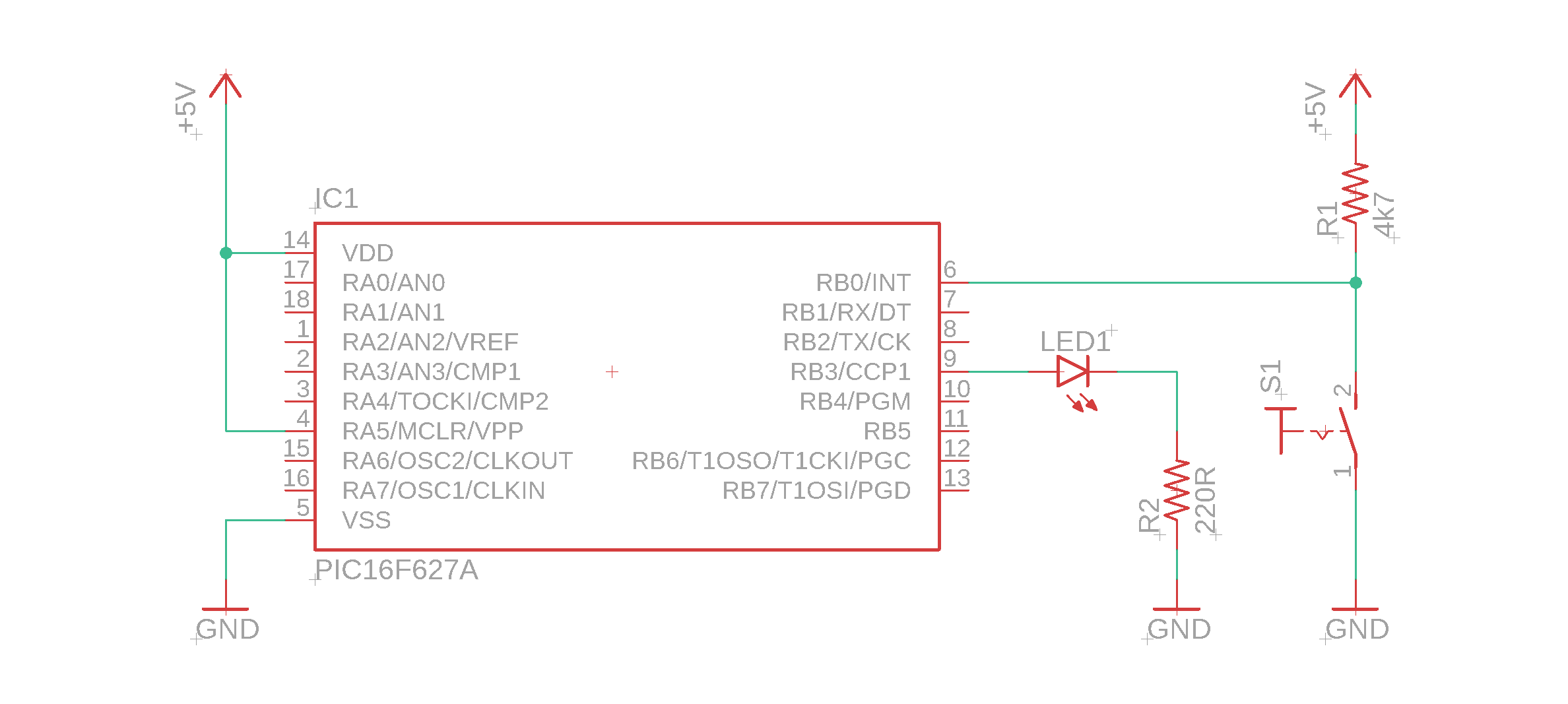
There is another potentially confusing ingredient to many schematics: labels. They are designed to make our life simpler, and they do, but you first have to know what they do. Let's take a look at the pushbutton circuit we developed last week:
And, for the heck of it, let us imagine that it is a bit more complicated with some stuff connected to the remaining pins RB1, RB2, RB4, RB5, RB6, and RB7:
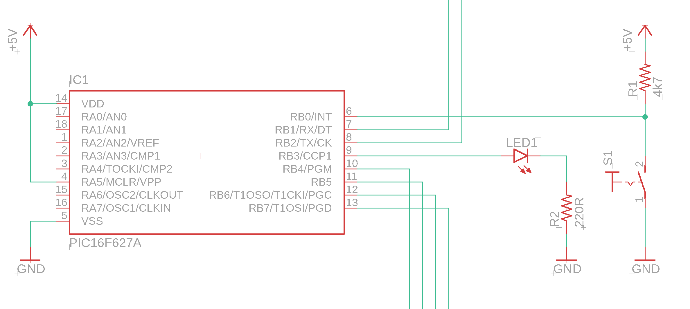
It is starting to look messy, isn't it? This is where labels come in. Instead of having a lane that crosses a bunch of others (more on that in the next section) we can also use a label:
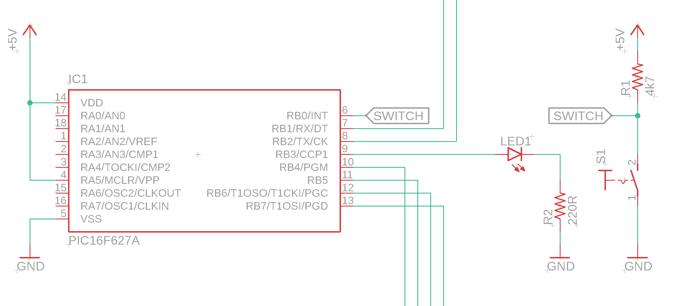
This schematic is the same as the one above, but we replaced the horizontal lane with two labels with the same name (“SWITCH”). Anything that is connected to that label is also connected to each other. We see: this is exactly the same idea as we already encountered for the supply symbols.
Junctions
As we have seen above, schematics can become quite messy at times. Time for another example! Look at the Chicago Circle interchange:
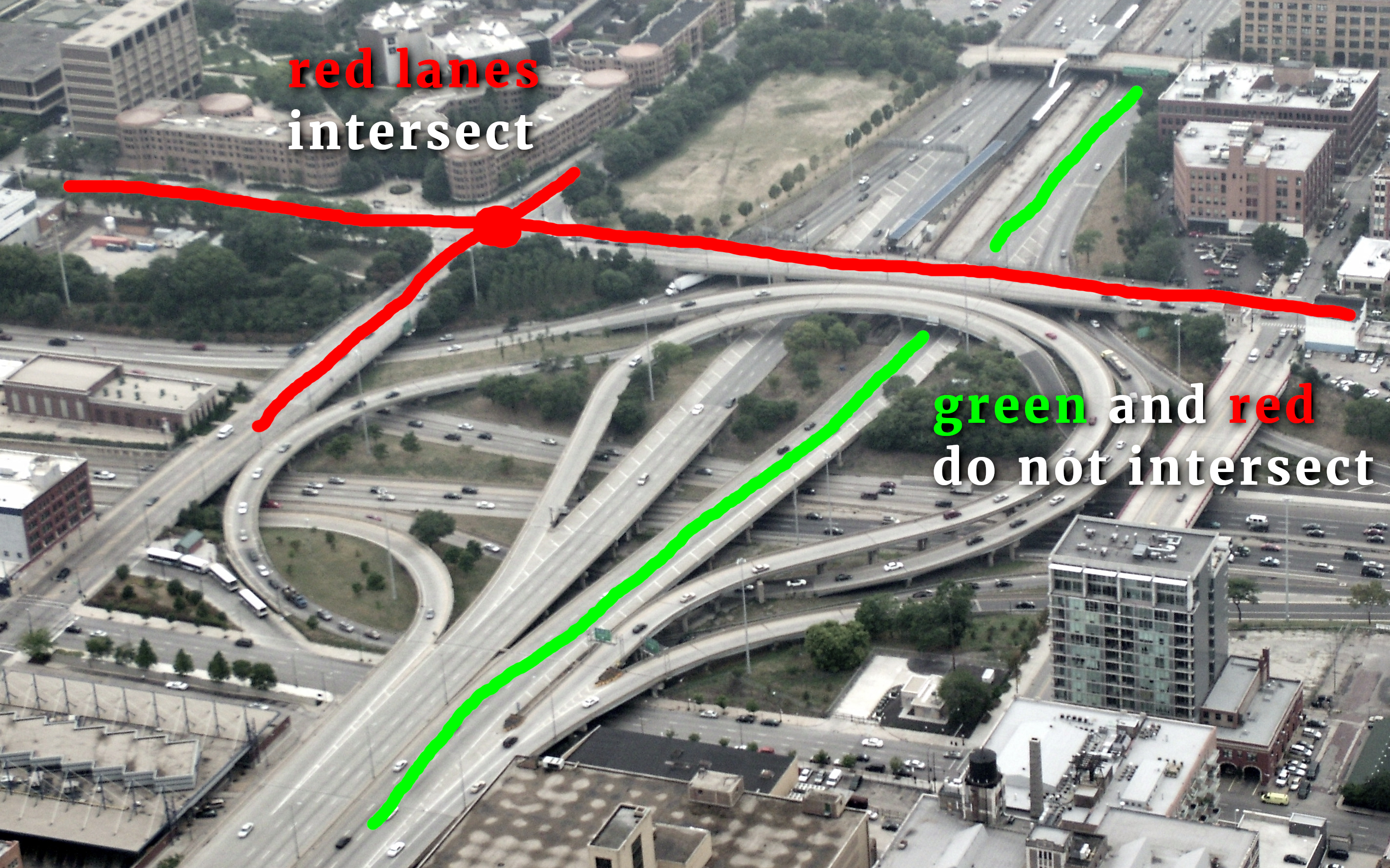
It is quite important that a few of these lanes in fact intersect, but most of them don't. This is usually fairly easy to see for streets and highways. On schematics it can be a bit more difficult.
Take a look, for example, at a magnified version of the circuit above. It is perhaps not as complicated as a true spaghetti junction, but still, you get the idea. Let us focus on the red and green lane:
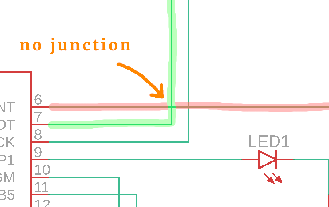
These lanes cross but do not intersect. Say, for a second, that the schematic would look like this instead:
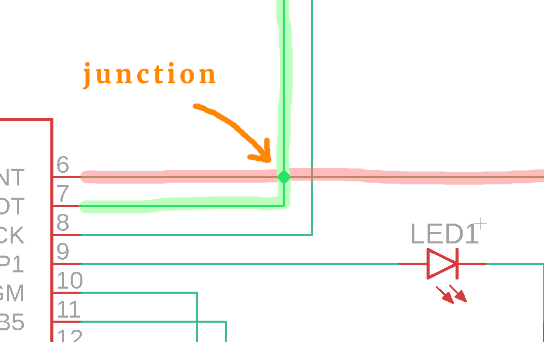
Then the lanes would intersect. This dot on the lanes is called a “junction.” Whenever there is a junction dot, two crossing lanes are electrically connected to each other. When there is not dot, then they just cross (like a bridge over a road).
Sometimes people forget to draw the junctions properly in their schematics, and if you are confused about it: just ask! And also ask yourself: does it make sense if they are connected? In the above example it doesn't make any sense to connect them: this would connect two of the PIC's pins, and that is almost never a good idea.
Conventions
I learned electronics in Europe, but now I live in North America. And I had to learn that a few symbols and names are slightly different. It is not really a big deal, but it helps to have it in mind.
The most striking differences are with resistors, capacitors, and coils:
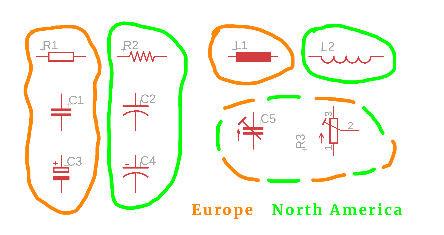
The above image is pretty self-explanatory. What I find interesting is that the trim capacitor C5 and potentiometer R3 share the same symbol between Europe and North America. Does anybody know why?
Final tip: divide and conquer!
If you are intimidated by a schematic (this will happen, it happens to all of us) then the best way to deal with it is to split it into smaller parts that you can understand. If already the Romans believed in this principle there might be some truth to it ;-)
Once you understand the smaller parts, you can forget about them. And, before you know it, the schematic will make more sense to you, because you learned to focus on the important things systematically.
I do realize that this may sound a bit empty, and at this point you are surely right. We haven't seen a really complicated schematic in our tutorials yet. I will save that for another time :)
So, what do you think? Did I miss something terribly important? Get in touch on social media and let me know :)


