How to use light-dependent resistors (LDRs) with microcontrollers
January 13, 2020 • tutorial
Microcontrollers show their true potential when we connect them with sensors providing the microcontroller with information about the real world. In this tutorial we will learn how to connect a simple light-dependent resistor (LDR) to a PIC microcontroller that allows us to have the controller react to the ambient brightness.
In order to convert the brightness level into a digital number that the microcontroller can understand we will use a simple voltage divider circuit in combination with a microcontroller's analog to digital converter (ADC), and we will finish up with a small sample circuit around the PIC16F1455 that we already know from our electronic candle project, turning on an LED when the brightness goes below a certain level. Let's go!
Some basics: conductors and insulators
Very broadly speaking, electric materials are either conducting or non-conducting. All the non-conducting materials are usually called insulators. So we distinguish between conductors on the one side, and insulators on the other. Semiconductors are in between. OK, great!
But why are some materials conductors and some other materials insulators?
We need to remember that electric current is nothing but electrons that move through a wire. Electrons are elementary particles that, together with protons and neutrons, make up every single atom you could ever encounter. Okay, so the movement of electrons corresponds to a current. On the other hand, when electrons cannot move the material does not conduct current, and is an insulator.
So how can we find out if electrons can move freely in a material or not? At this stage we have to use quantum physics and calculate the motion of electrons in a given material. This sounds very complicated, but we can simplify this by looking at the energy of an electron and compare it to the so-called Fermi level of the material. The Fermi level is the highest energy of an electron that is still bound to the material.
Here you can see a sketch of that idea:
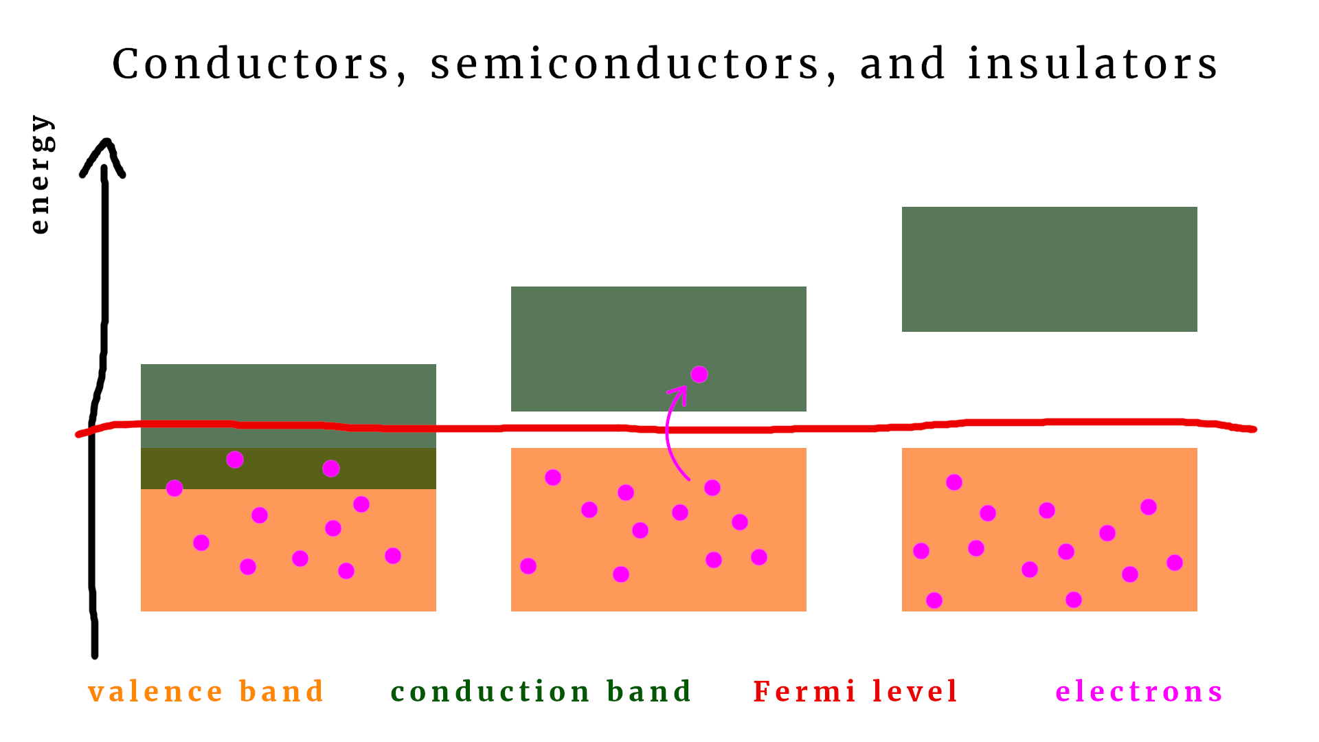
On the vertical axis you can read off the energy of an electron (purple dots). Let's understand it step by step.
- If the energy of an electron is larger than the Fermi level it is in the conduction band: it is no longer bound and can move freely through the material and can be part of a current. This condition is satisfied in the leftmost diagram, which is why it depicts a conductor.
- If the energy of an electron is less than the Fermi level, the electron is said to be in the valence band: it is bound to its atom, it cannot move, and it cannot be part of a current. That is the case in the rightmost diagram, which is why it is an insulator.
- And yes, you guessed it: the middle diagram depicts a semiconductor, wherein the conduction band and the valence band are very close together. In fact, they are so close together that small thermal excitations (say, the room temperature) can be enough top kick an electron from the valence band into the conduction band.
As you can see: the concept is very simple. By the way, the term “band” comes from condensed matter physics and we should not worry too much about it (unless you want to study physics). The main message is the following:
The energy of an electron in a material determines if it can be part of a current or not.
Why should we care? Light-dependent resistors (LDRs) use the so-called photoelectric effect to kick electrons from the valence band into the conduction band. For that reason, LDRs contain a semiconductor material. Just like in the explanation above, a small external energy is enough to kick an electron into the conduction band. In this case it is not thermal energy, but rather the energy of incoming light.
In a nutshell: LDRs work because the incoming light makes a special semiconductor material inside of them become conducting. If that light is turned off again, the electrons are no longer kicked into the conduction band, and the LDR becomes insulating again.
Light-dependent resistors, photodiodes, and phototransistors
Here you can see a light-dependent resistor (LDR) in closeup:
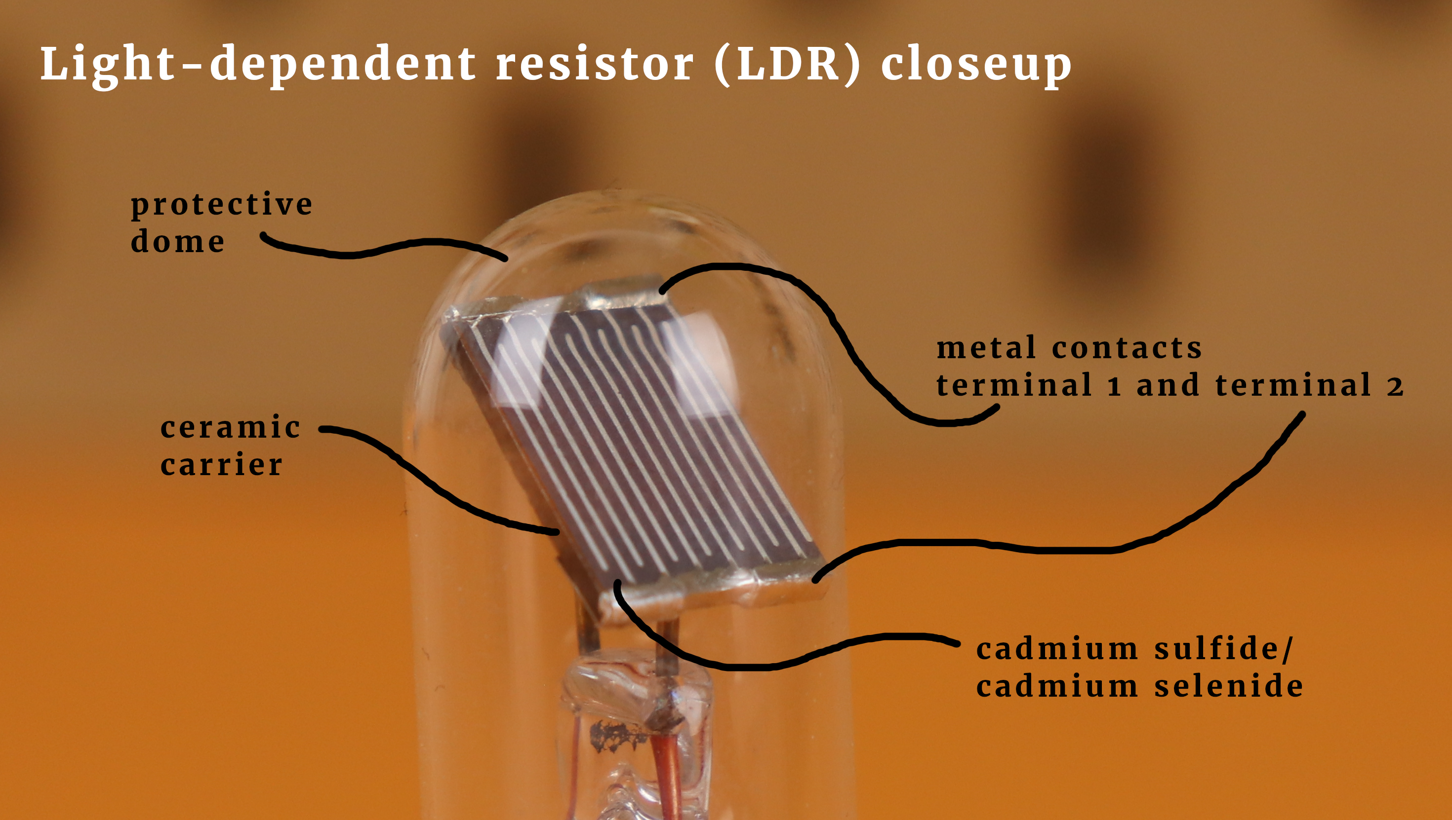
The two metal terminals are mounted on a ceramic substrate and are therefore not in electrical contact. They are isolated from each other. In between the meander-shaped contacts, however, is where the magic happens: there is a special semiconductor material (often it is cadmium sulfide or cadmium selenide) that is susceptible to the photoeletric effect that effectively makes the semiconductor a true conductor when we turn on some light.
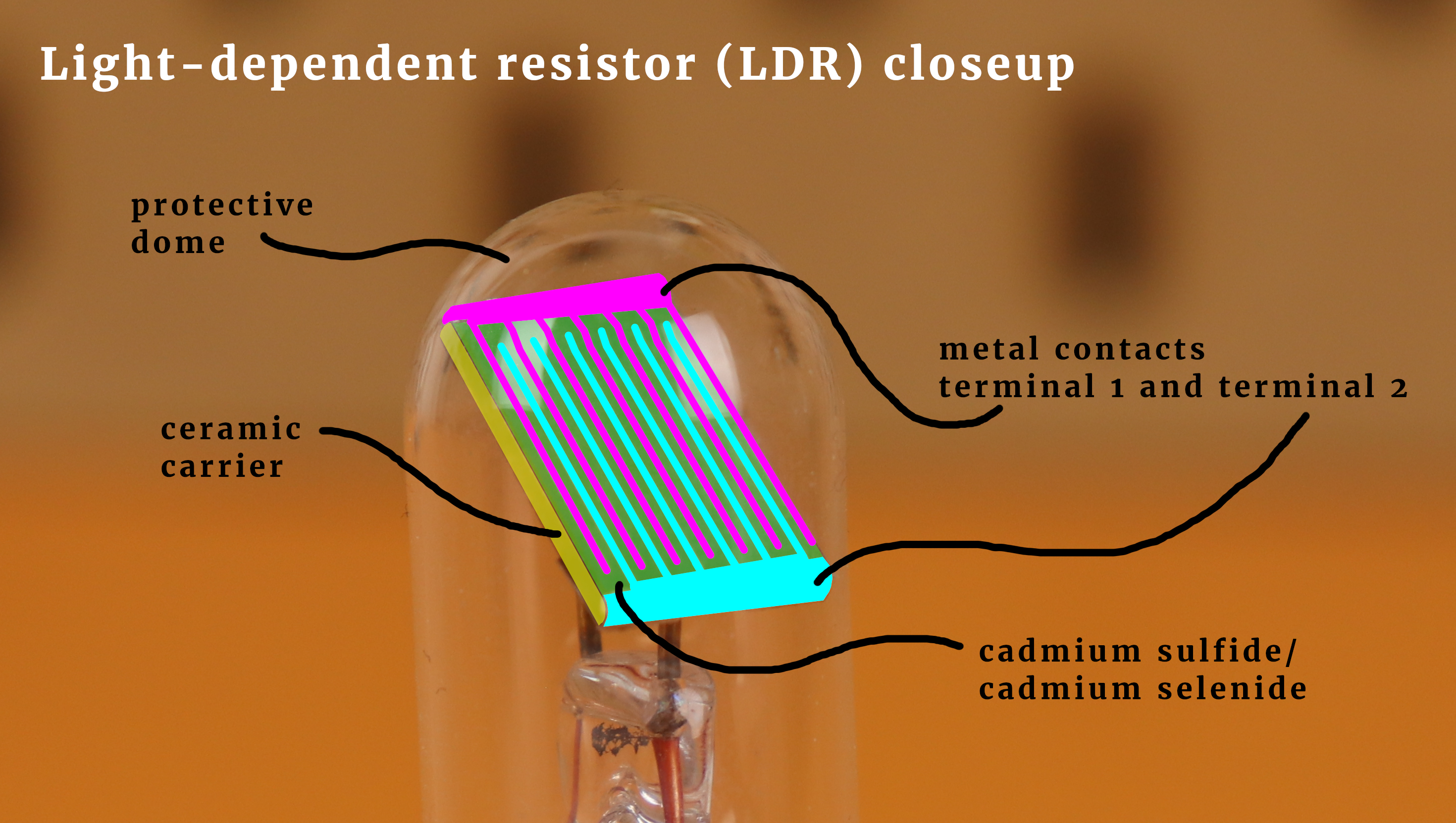
Here is the same image again, but with some additional colors to highlight the individual components:
The LDR depicted above is somewhat atypical, however. More standard packages look like this (I am sure you have seen them somewhere before):
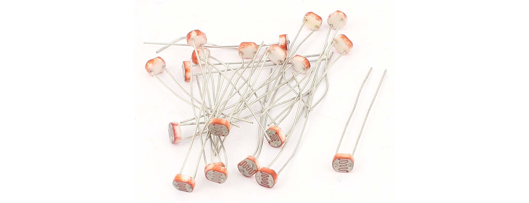
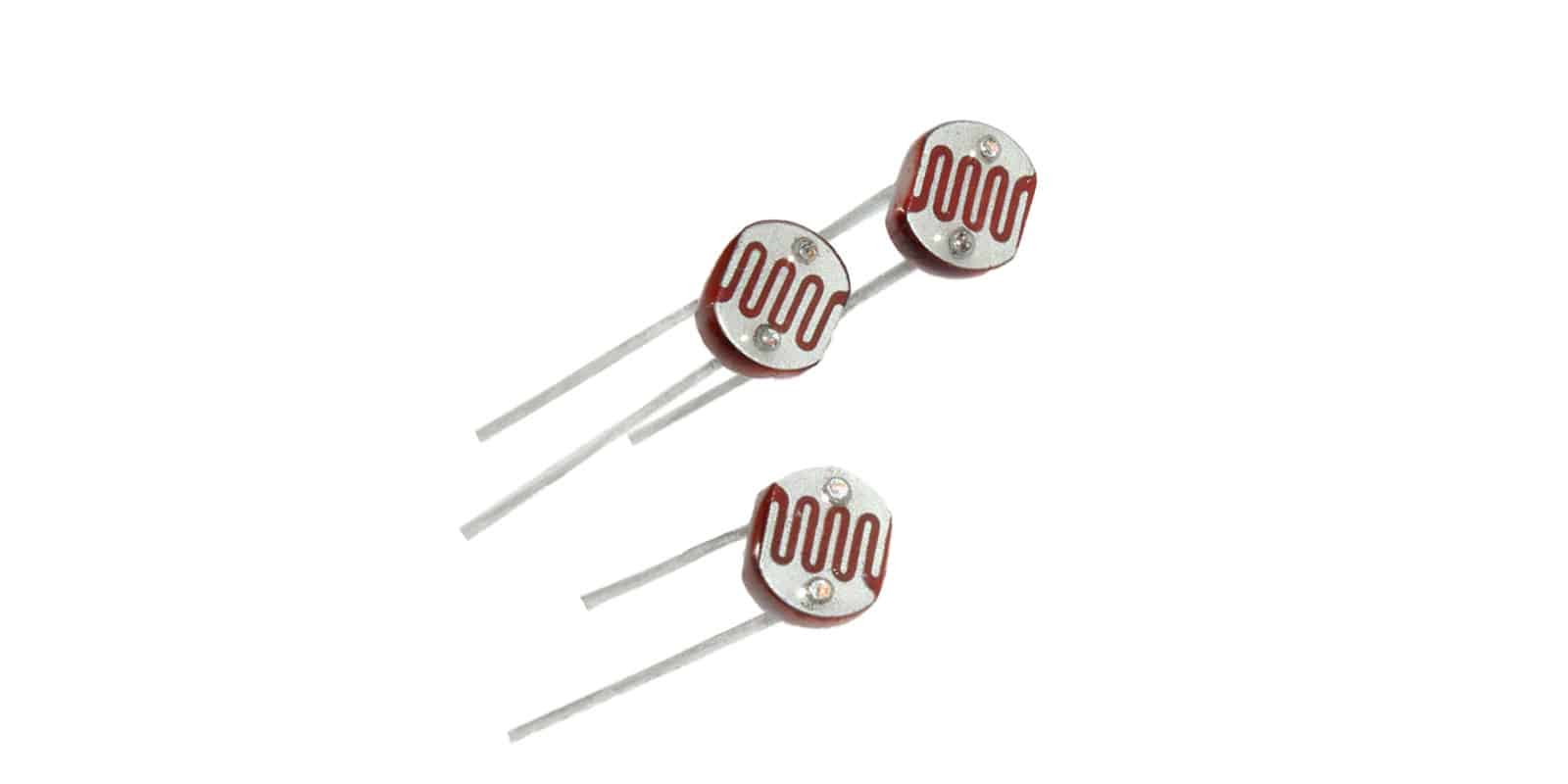
LDRs are very cheap and can be bought by the hundreds for just a few dollars. LDRs have some important characteristics:
- ON resistance: when they are fully illuminated, the resistance is typically a few dozen Ohms. For example, the depicted LDR in the above has a resistance of around 30Ω when exposed to my studio lights.
- OFF resistance: when thy are surrounded by darkness, the resistance is much higher. My LDR's resistance increases to around 150kΩ.
- LDRs are slow, especially the older ones from times where the manufacturing process of semiconductor materials was not as reliable as it is today. Slow means that it can take a few milliseconds up to a couple of seconds or even minutes (in extreme cases) for some LDRs to settle for a stable resistance after the brightness level is either increased or decreased rapidly. For this reason LDRs are useful as ambient light sensors, but not useful for data transmission via light pulses.
If you want to measure brightness levels at much shorter time scales, you will need an active semiconductor device that makes use of a so-called PN junction. These are either diodes or even transistors that contain a photosensitive material. Here you can see a few of them:
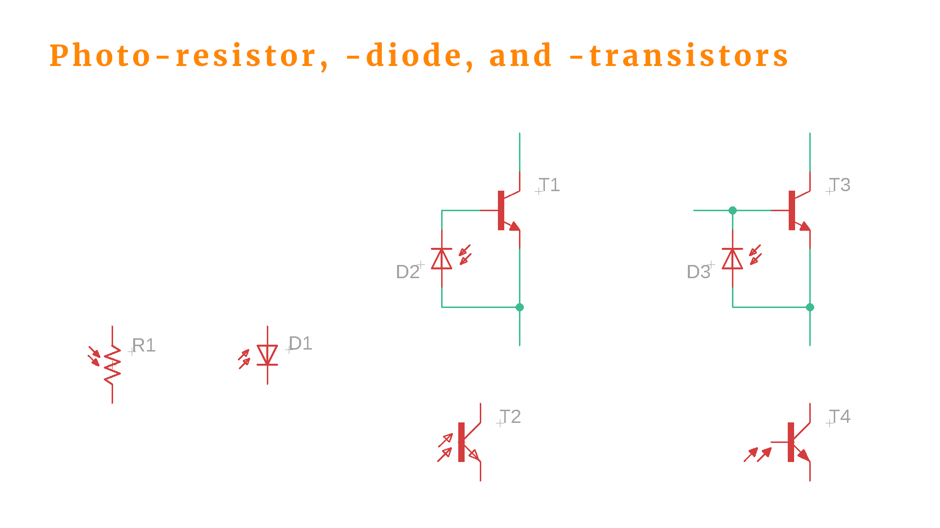
- On the left you can see our good old LDR that I only included for completeness. Speaking of completeness, LDRs are not only called light-dependent resistors but also go under the name photoresisor.
- D1 is a so-called photodiode. Its symbol almost looks like an LED, but for LEDs the arrows point away from the diode, not towards it :) In darkness it works as a regular diode, but that diode functions breaks down when exposed to light. For this reason photodiodes are used in so-called reverse bias circuits. Photodiodes also geenrate a small photocurrent when exposed to light.
- If you combine an NPN transistor T1 with a photodiode D2 you obtain a phototransistor T2. It essentially works like a regular transistor, but the base current is generated by a photodiode. This means that the transistor is capable of switching currents that are much larger than the small photocurrent.
- T4 is also a phototransistor (formed by an NPN transistor T3 with a photodiode D3) but its base pin is accessible which can be useful to further tune the behavior of the transistor threshold.
Photodiodes and phototransistors are active components, whereas an LDR or photoresistor is a passive component. Let me know if you want to learn more about photodiodes and phototransistors, and we can cover them in a future tutorial or article! For the rest of this tutorial, however, we will focus on LDRs, and, in particular, how we can connect them to a microcontroller.
Voltage dividers
These simple circuits are very useful when working with resistive sensors such as LDRs. There are also many other sensors that are resistive, so even if you don't plan on using an LDR anytime soon, this concept may still be relevant to you at some point :) Here you can see a typical voltage divider:
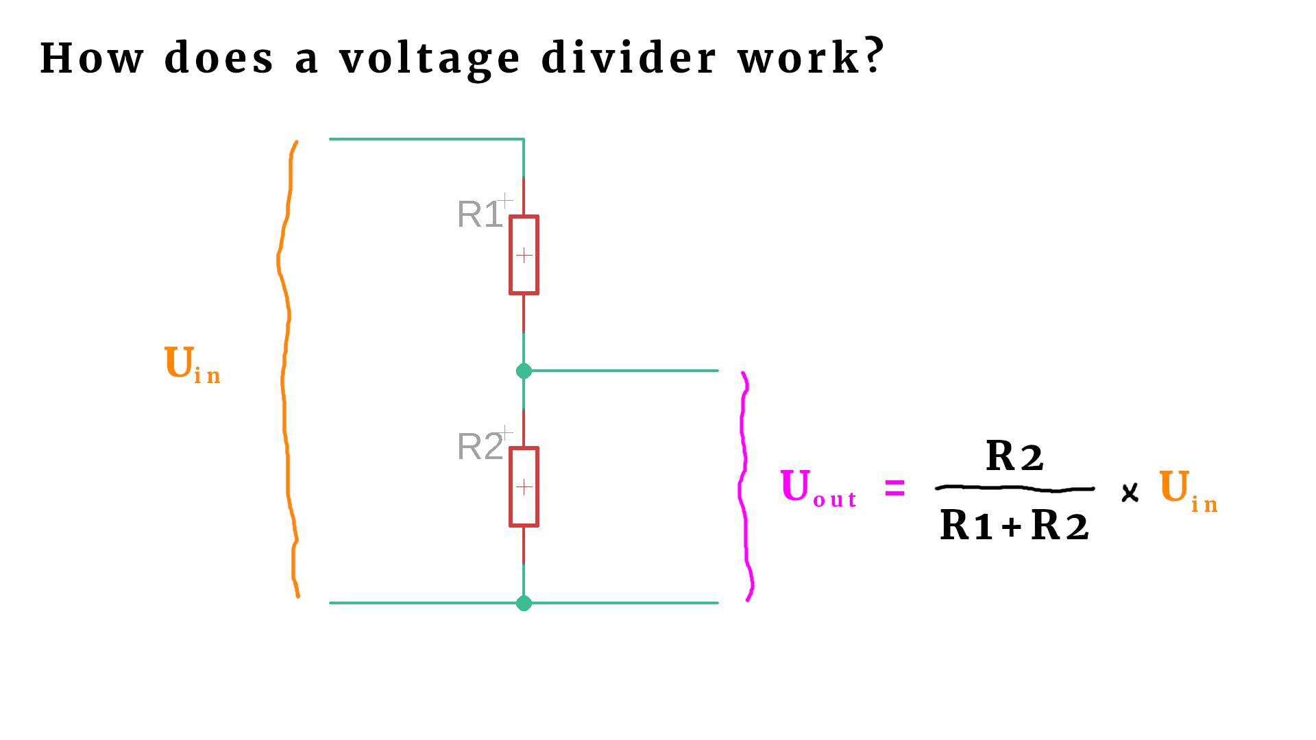
The name voltage divider comes from the fact that the voltage Uin is broken down into a smaller voltage Uout, where the ratio can be adjusted with the two resistors R1 and R2. If you know one of the resistors, say R1, and you know the total voltage Uin, then the voltage divider can be used to determine R2 by simply measuring the voltage Uout.
Another way to think about this circuit is to consider extreme cases (which are all consistent with the mathematical formula):
- If R1 becomes infinite (e.g. when you remove it), the output voltage has to be zero.
- If R1 is zero (e.g. if you replace it by a wire) then Uin and Uout are the same.
- If R2 becomes infinite (e.g. when you remove it), Uin and Uout are also the same.
- If R1 = R2, the output voltage Uout is exactly 1/2 of the input voltage Uin.
I like this kind of approach: based on some simple limits we can convince ourselves rather quickly if a formula makes sense or not. Trust your intuition :)
Reading out an LDR via a microcontroller
Now we can replace either R1 or R2 with an LDR and read out the voltage Uout with a microcontroller's analog to digital converter (ADC). This is the circuit:
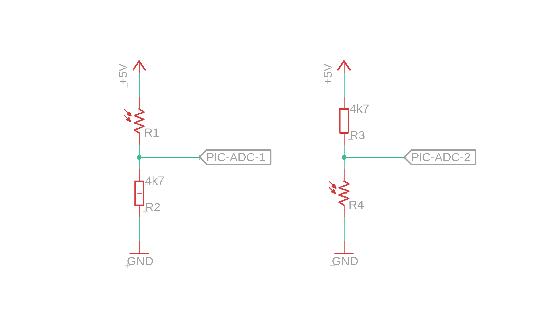
Why are there two options? Let's look at them separately:
- First, we need to remember that an LDR becomes conducting if light shines onto it.
- For this reason, the circuit on the left measures brightness: the voltage increases as it gets brighter and R1 decreases.
- The circuit on the right, on the other hand, measures darkness.
Of course this does not really matter when you connect the circuit to a microcontroller, and in that case both circuits are equally sensible. If, on the other hand, you want to connect an LDR voltage divider to external analog circuitry, the above distinction may become important :)
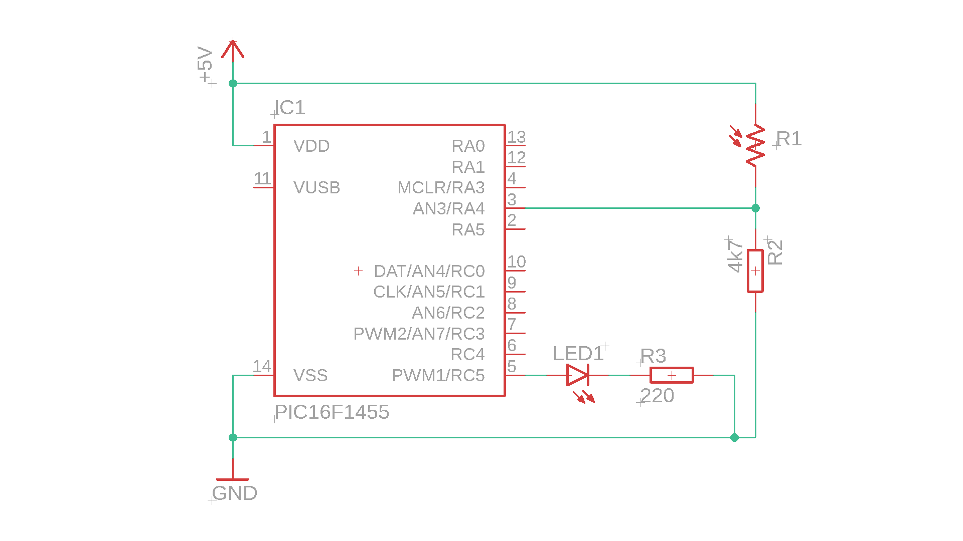
Example: switching on an LED when it gets dark
This is a simple example circuit that uses the PIC16F1455's analog to digital converter module to read out the output voltage of the voltage divider formed by R1 and R2, and this voltage measures the brightness.
You can find the source code in the appendix and the compiled .hex file in the resources box, if you want to build the little circuit. The program is essentially just a variation of the electronic candle program. Here is the main loop:
	// main loop
    while (1) {

        // read out the brightness ADC value (will be between 0 and 255)
        CHS0 = 1; CHS1 = 1; CHS2 = 0; GO = 1; while (GO);
        brightness = ADRESL;

        // turn LED ON if brightness is less than half
        if (brightness < 127) {
            LED = 1;
        } else {
            LED = 0;
        }

    }
In lines 67-69 we read out the ADC value, which in this case is between 0-255. In line 71-76 we react to the brightness value. If it is less than half, we turn the LED on, and if not, we turn it off.
This code is not ideal for some reasons. First of all, the main program is paused while we wait for the ADC conversion result (and it can be done more elegantly and resource-friendly with interrupts). But the more serious problem is the following:
Imagine the brightness level is at 126, so the LED is turned ON. When the LED is ON, the ambient brightness might be slightly more than 127 (because some part of the LED's light might find its way back to the LDR). But then, of course, since the brightness level is more than 127, the LED will turn OFF again, and the cycle repeats itself. This behavior is unstable and is sometimes called a feedback loop. So, in a real-life application, this would not be sufficient :)
Final thoughts

I hope this tutorial was interesting to you, and you consider using an LDR in your next project. These are fascinatingly simple little devices, with many possible applications. If something was not clear or could be explained better, please get in touch on social media and I'll do my best to get back to you. Thanks for reading!
Appendix: The full source code
Here you can find the full source code. The code (as well as the .hex file) are also available for download in the resources box.
/*
 * File:   main.c
 * Author: boos
 *
 * Created on January 13, 2020, 7:36 PM
 */

// CONFIG1
#pragma config FOSC = INTOSC    // Oscillator Selection Bits (INTOSC oscillator: I/O function on CLKIN pin)
#pragma config WDTE = OFF       // Watchdog Timer Enable (WDT disabled)
#pragma config PWRTE = OFF      // Power-up Timer Enable (PWRT disabled)
#pragma config MCLRE = OFF      // MCLR Pin Function Select (MCLR/VPP pin function is digital input)
#pragma config CP = OFF         // Flash Program Memory Code Protection (Program memory code protection is disabled)
#pragma config BOREN = OFF      // Brown-out Reset Enable (Brown-out Reset disabled)
#pragma config CLKOUTEN = OFF   // Clock Out Enable (CLKOUT function is disabled. I/O or oscillator function on the CLKOUT pin)
#pragma config IESO = OFF       // Internal/External Switchover Mode (Internal/External Switchover Mode is disabled)
#pragma config FCMEN = OFF      // Fail-Safe Clock Monitor Enable (Fail-Safe Clock Monitor is disabled)

// CONFIG2
#pragma config WRT = OFF        // Flash Memory Self-Write Protection (Write protection off)
#pragma config CPUDIV = NOCLKDIV// CPU System Clock Selection Bit (NO CPU system divide)
#pragma config USBLSCLK = 48MHz // USB Low SPeed Clock Selection bit (System clock expects 48 MHz, FS/LS USB CLKENs divide-by is set to 8.)
#pragma config PLLMULT = 3x     // PLL Multipler Selection Bit (3x Output Frequency Selected)
#pragma config PLLEN = ENABLED  // PLL Enable Bit (3x or 4x PLL Enabled)
#pragma config STVREN = ON      // Stack Overflow/Underflow Reset Enable (Stack Overflow or Underflow will cause a Reset)
#pragma config BORV = LO        // Brown-out Reset Voltage Selection (Brown-out Reset Voltage (Vbor), low trip point selected.)
#pragma config LPBOR = OFF      // Low-Power Brown Out Reset (Low-Power BOR is disabled)
#pragma config LVP = ON         // Low-Voltage Programming Enable (Low-voltage programming enabled)

#include <xc.h>

// global variable
static unsigned char brightness = 0;

// define LED
#define LED RC5

void main(void) {

    // set internal oscillator to 4MHz
    IRCF0 = 1;
    IRCF1 = 0;
    IRCF2 = 1;
    IRCF3 = 1;

    // set LED to output
    TRISC5 = 0;

	// ADC sampling frequency per bit is F_osc/2
	ADCS0 = 0;
	ADCS1 = 0;
    ADCS2 = 0;

    // result alignment
    ADFM = 1;

	// RA4 is an analog inputs
	TRISA4 = 1;
    ANSA4 = 1;

	// turn the ADC on
	ADON = 1;

    // main loop
    while (1) {

        // read out the brightness ADC value (will be between 0 and 255)
        CHS0 = 1; CHS1 = 1; CHS2 = 0; GO = 1; while (GO);
        brightness = ADRESL;

        // turn LED ON if brightness is less than half
        if (brightness < 127) {
            LED = 1;
        } else {
            LED = 0;
        }

    }

    return;

}


