DS1302 real-time clock tutorial: the clock that doesn't forget the time!
November 4, 2020 • tutorial
Whenever you are building a clock with a microcontroller there is a problem: when you turn off the power, the time is lost. This is where a real-time clock comes in. It's a handy little integrated circuit that uses a small battery to keep track of the time whenever the main power is disconnected. And in today's tutorial we will learn all about it: how to use it with a microcontroller and how to store custom bits and bytes on there as well.
So let's go ahead and learn how to build a clock that doesn't forget the time! If you want to follow along with this tutorial, here is all you need (and check out the YouTube video too if you want):
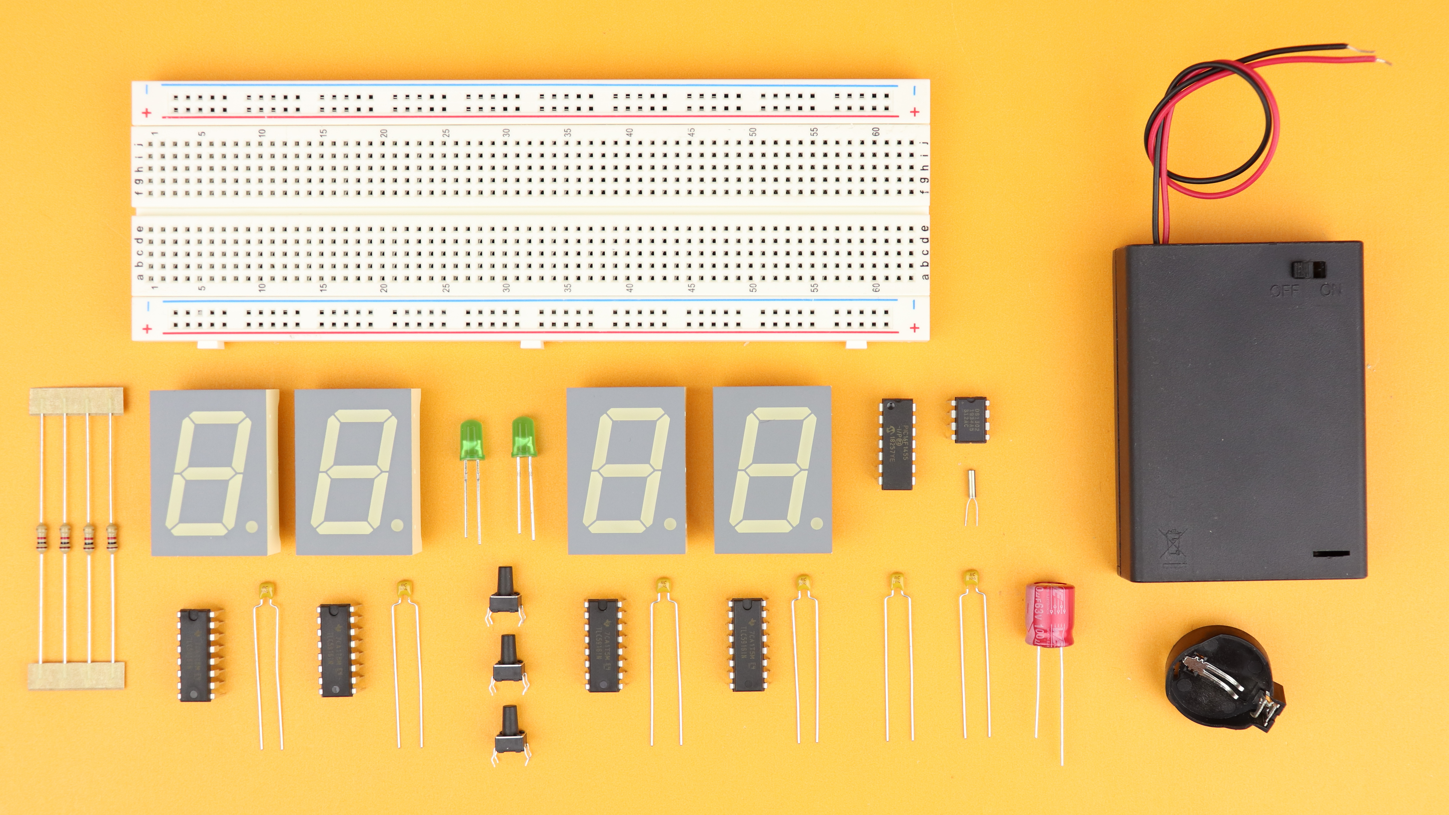
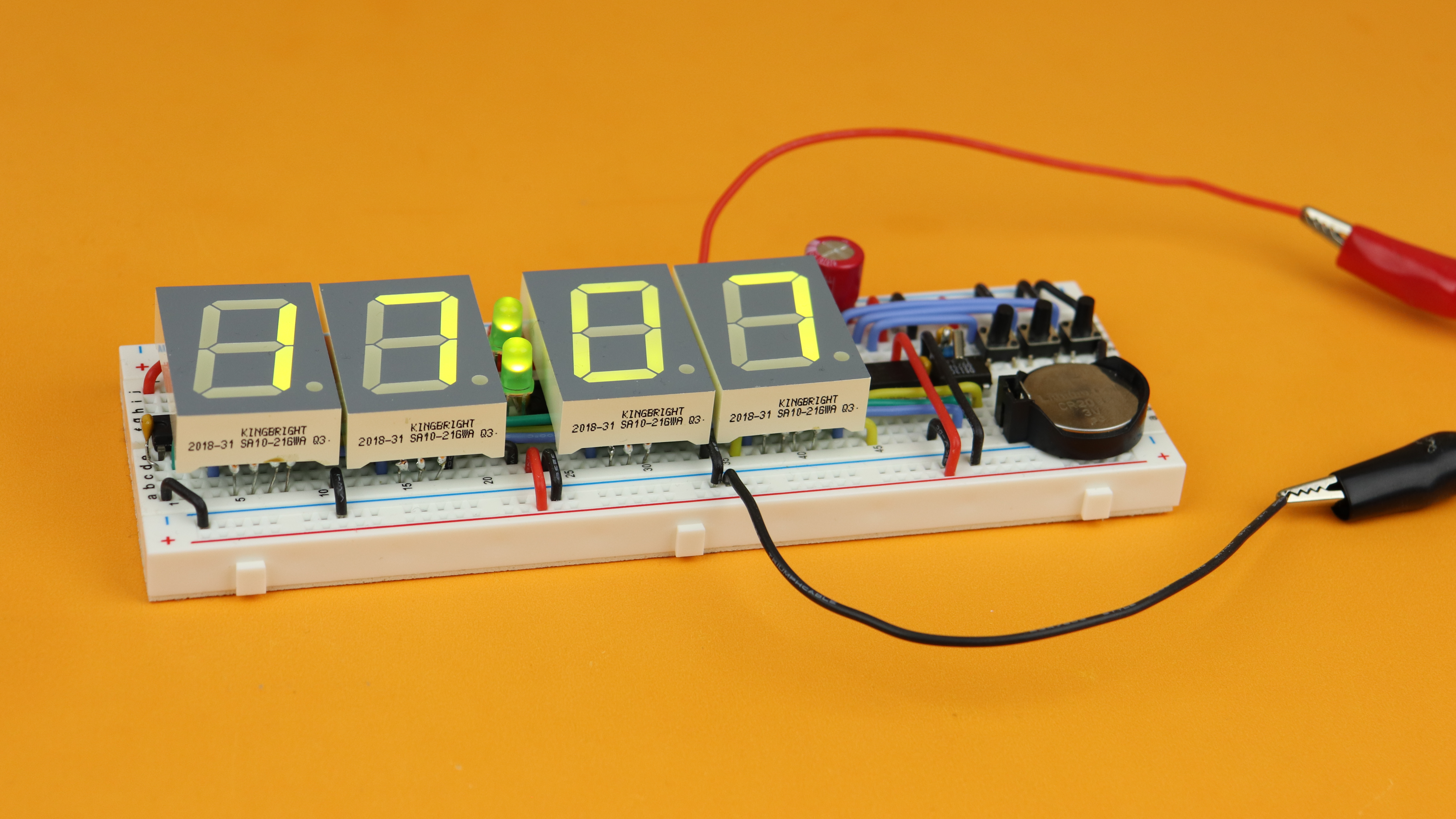
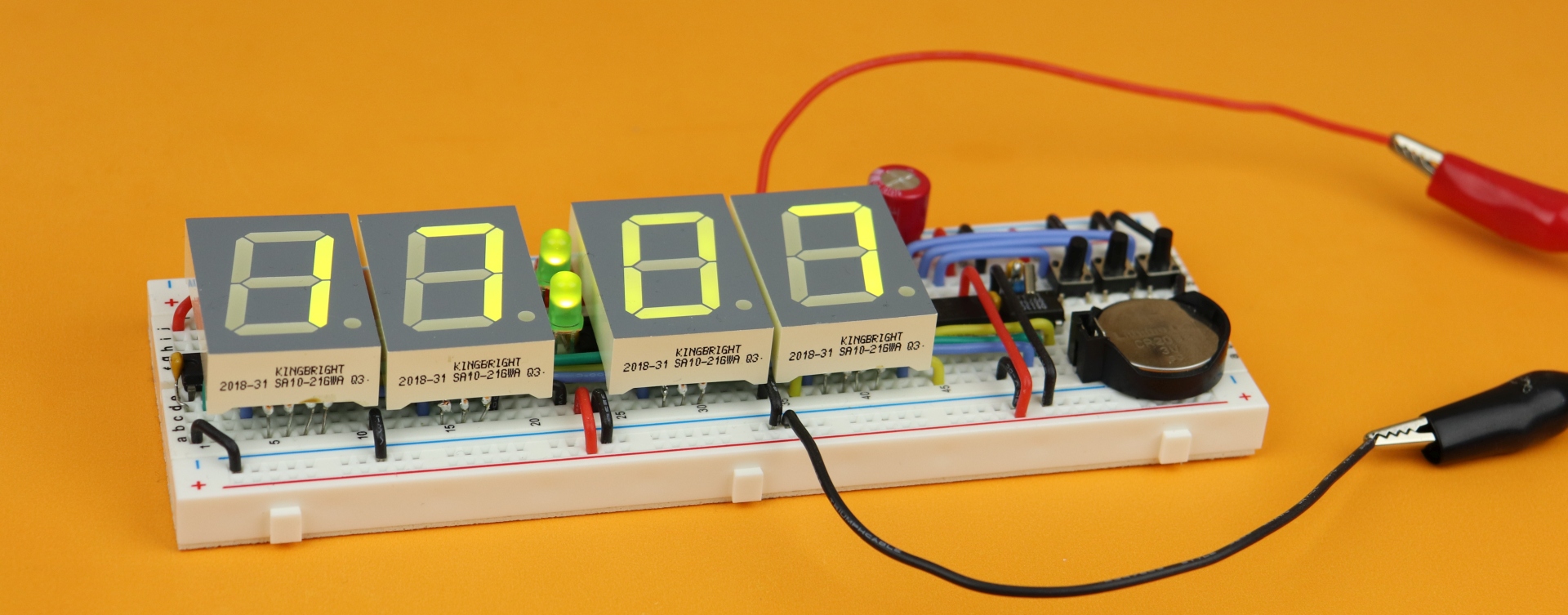
Check out the components box to links of all the components. And here is how the final clock will look like:
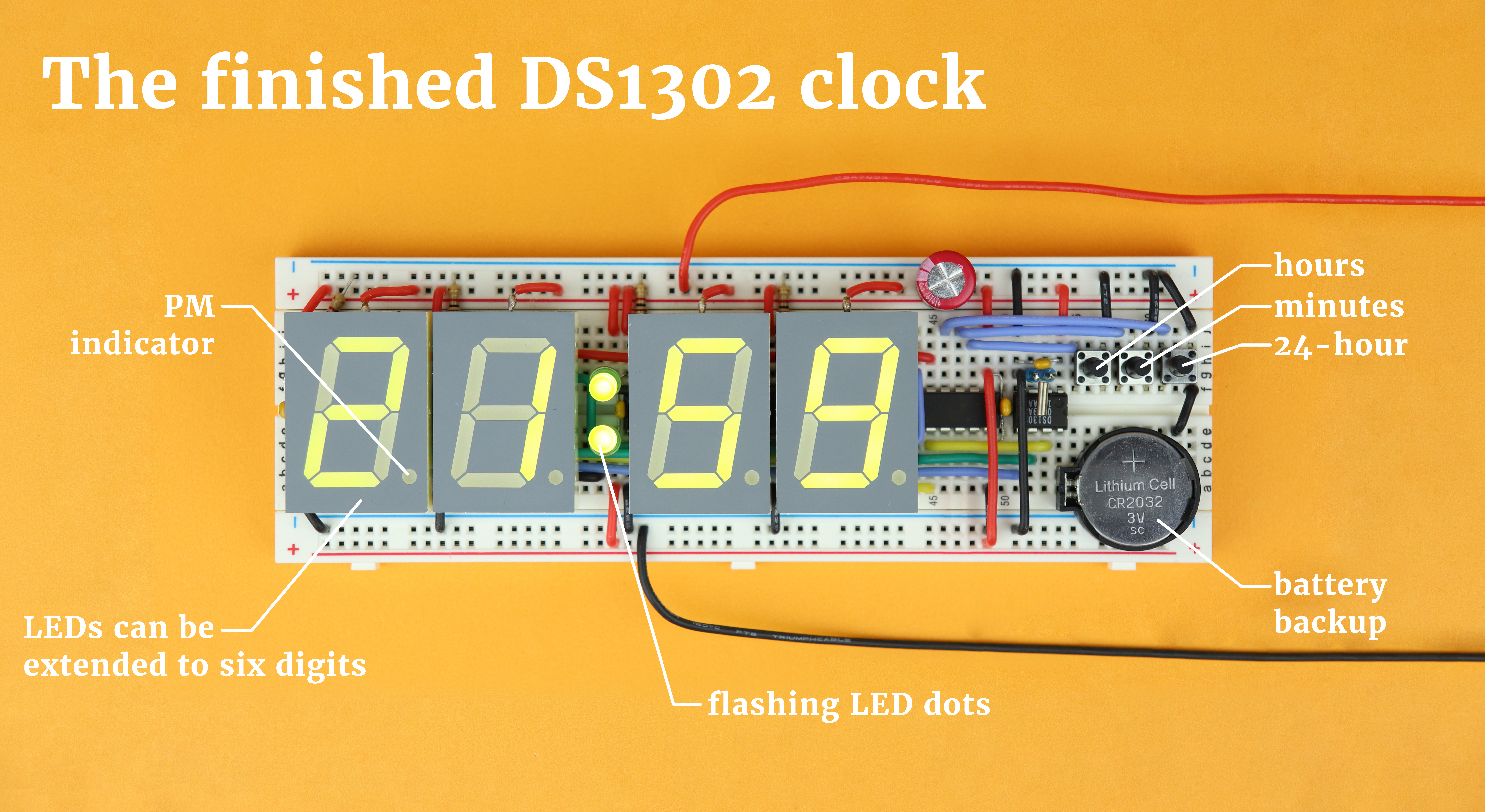
And here is how it works:
- The four 7-segment displays show the time in the HH:MM format.
- The LED dots in between blink once every second.
- You can extend everything to include seconds as well to arrive at a HH:MM:SS clock, more on that below.
- The left pushbutton increases the hours and the middle one increases the minutes. Whenever they are pressed, the seconds are reset to zero to allow for a precise time adjustment.
- Pressing the right pushbutton switches between 24-hour mode and AM/PM mode. When in AM/PM mode, the decimal point of the leftmost display works as the PM indicator.
- And the best part: the real-time clock DS1302 remembers all of that when the power is switched off! It will keep counting up the time and only needs the small CR2032 coin cell battery for that, and it will last for a very long time (years).
- The DS1302 can also store user information in its freely accessible RAM module, and here we use it for the clock to remember whether it's in 24-hour mode or in AM/PM mode, but you could also use it to store alarms or other stuff.
And for the rest of this tutorial we will learn how to program the microcontroller so that it does all that, and then build this clock step by step. Don't forget that you don't need to understand the microcontroller code in all its detail, you can still build this clock yourself just by using the .hex-file. Let's go!
Schematic
Don't be discouraged if the schematic looks a bit frightening at first, we will take it apart, piece by piece, until it all makes sense. Here it is!
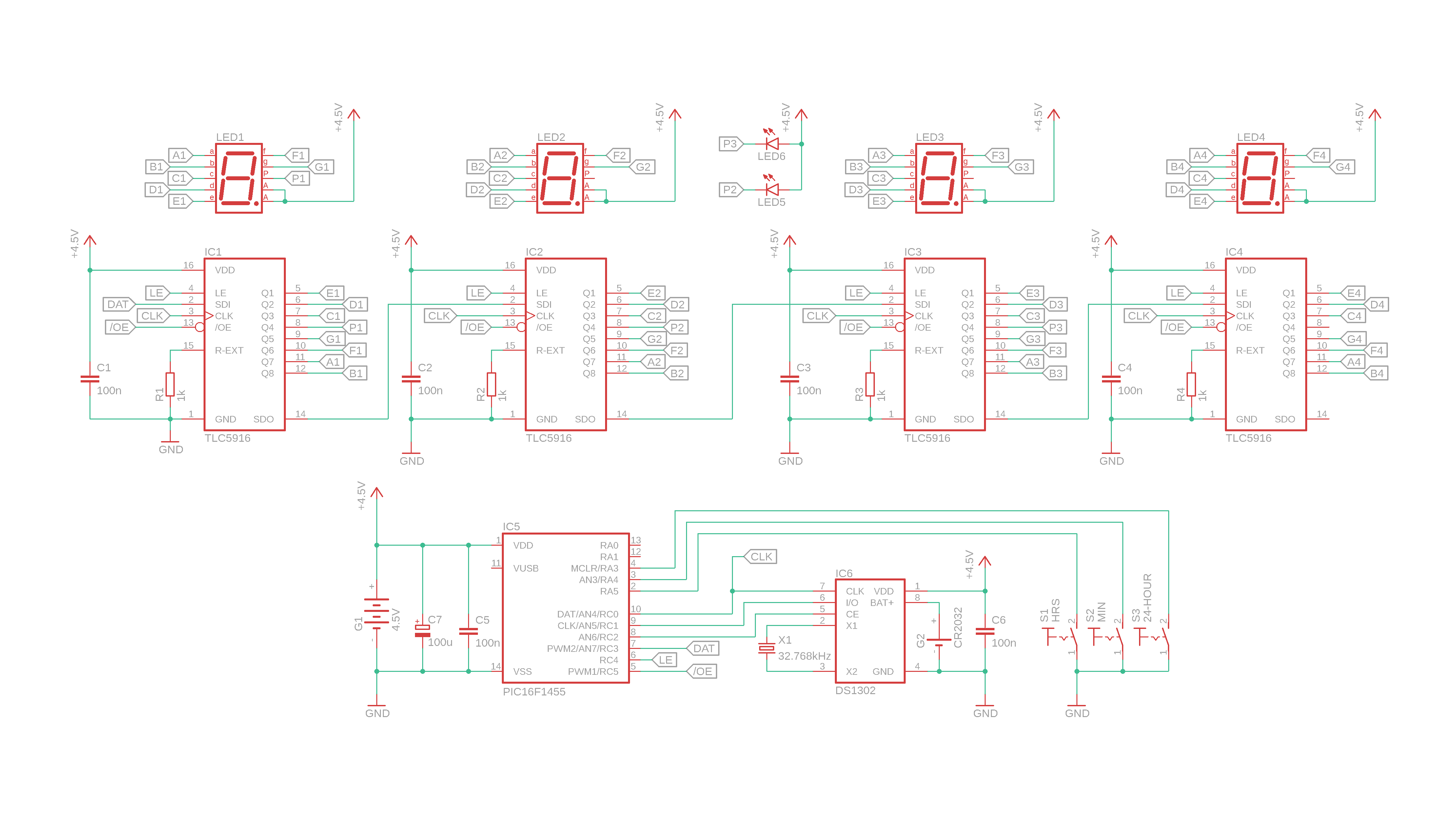
So, what do the difference components do? Let's look at the lower part first!
- G1 is our battery that will power the circuit, and C7 is a bulk capacitor. C5 is the bypass capacitor for IC5.
- Speaking of which, IC5 is the PIC16F1455 microcontroller that works as the brain of this circuit: it reacts to the user input via the pushbuttons, sends the time information to the LEDs, and communicates with the real-time clock.
- IC6 is the DS1302 real-time clock module, the real star of the show today. We will learn more about the DS1302 later, but in a nutshell it's basically a tiny clock with a battery backup (the CR2032 coin cell G2). C6 is another bypass capacitor, and X1 is a watch crystal that can be used to generate a stable 1Hz reference. The three pins CLK, I/O, and CE are data lines that can be used to transmit data between the real-time clock and the PIC16F1455.
- S1–S3 are pushbuttons for the user input, and the microcontroller has the internal pull-up resistors enabled so that it is enough for those switches to connect to ground whenever pushed. You can read more about that sort of thing here.
And now, let's focus on the upper part. And good news there, we already know all of it! Why? It's just a series of LEDs controlled by the TLC5916 driver IC which we we learned all about a few weeks ago. Basically the TLC5916 works as a shift register and LED driver in one. The 1kΩ resistors R1–R4 limit the current to 18.75mA, and the capacitors C1–C4 are bypass capacitors. The display data is sent from the PIC16F1455 to the SDI pin of IC1 and is then passed along through the TLC5916 drivers from left to right. Except for the leftmost display we are leaving the decimal point disconnected (because for the first display it serves as the PM indicator) and the two LEDs in the middle will serve as blinking dot. But that's it!
And, just to be cute, this can easily be extended to six displays! Because the data that is sent to the LEDs travels from left to right, we can just add two more displays and dots like this:
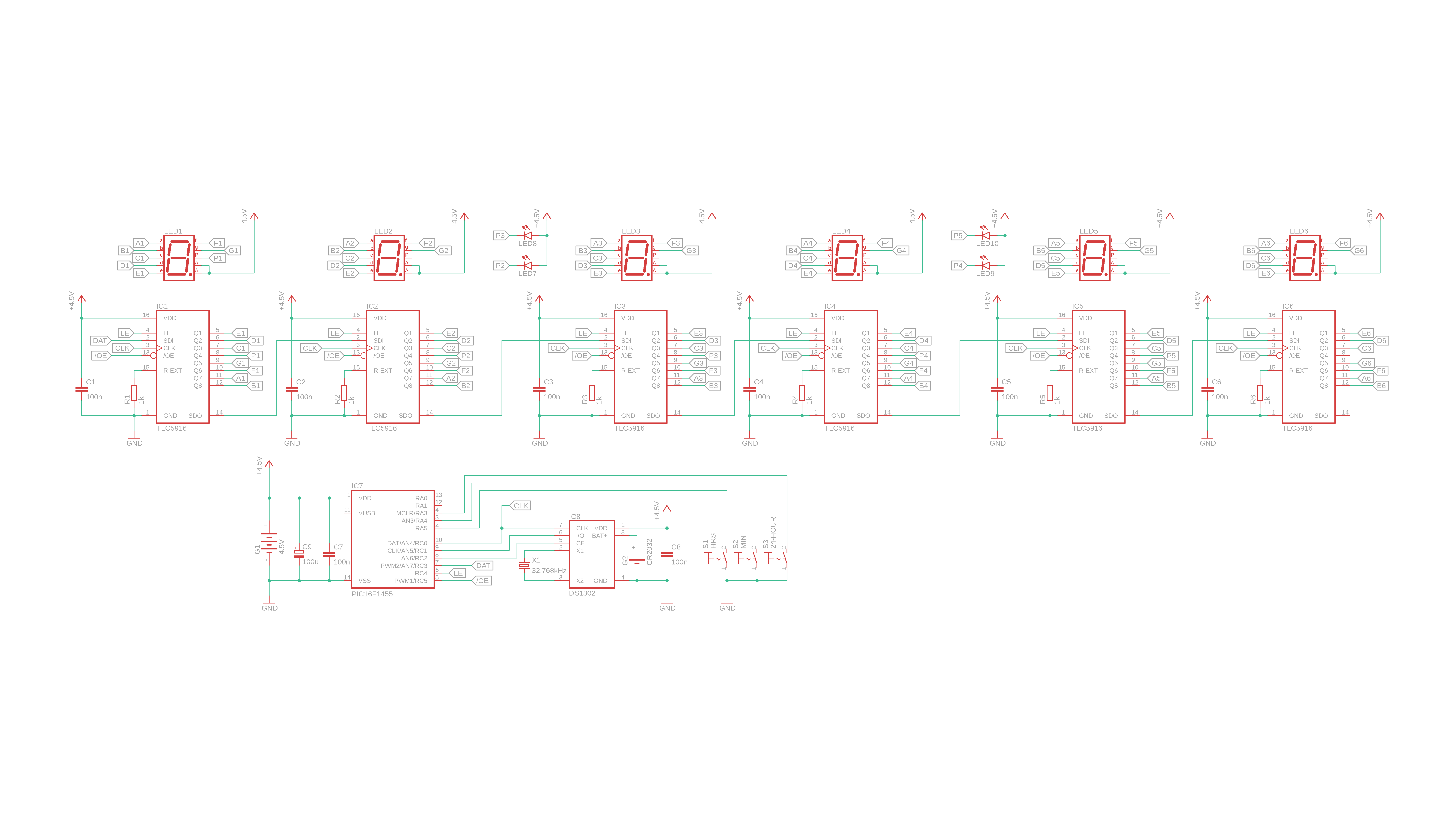
For this tutorial I will not focus on the six-digit version, mostly because it does not fit onto one breadboard, but the software we will talk about later actually is already written for six digits! This works nicely because if you only use four digits, the seconds information will leave the last TLC5916 before it becomes visible. If you have questions about getting the six-digit version to run, reach out on social media and I will do my best to get back to you :)
How to use the DS1302 real-time clock
Okay, before we talk about the software that is needed to make the PIC16F1455 talk to the DS1302 real-time clock we better learn how the DS1302 real-time clock works. It's really quite simple :)
Here you can see a typical DS1302 module that you can buy on Amazon or similar websites. It has all the main components we need, but since I don't like using external boards on simple breadboard projects I bought one of these modules and then desoldered the battery holder and the crystal.
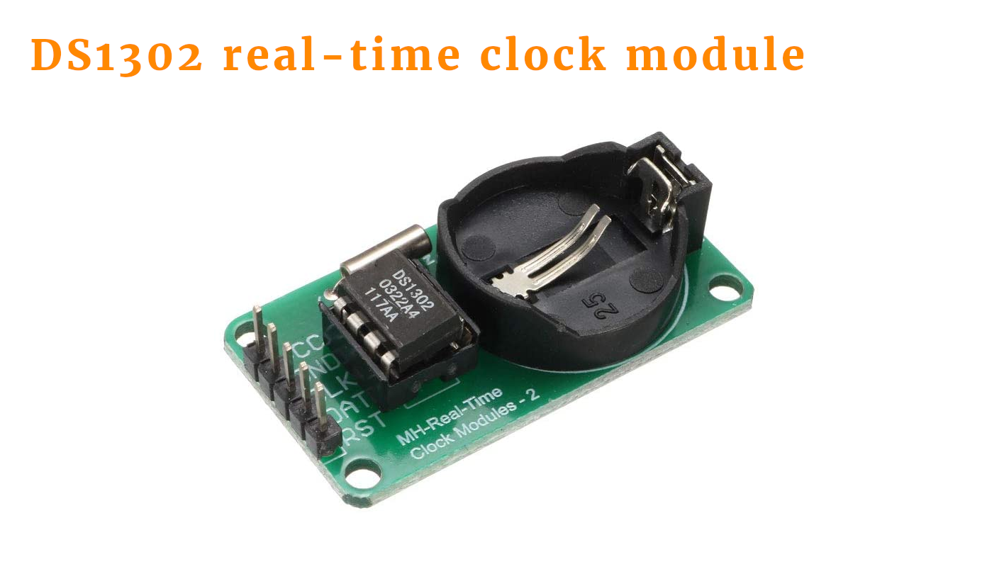
But hey, if you don't want to solder then this module is a great choice for you, and you can find a link to this type of PCB in the components box.
So how does the DS1302 work? Here is an overview of its main components:
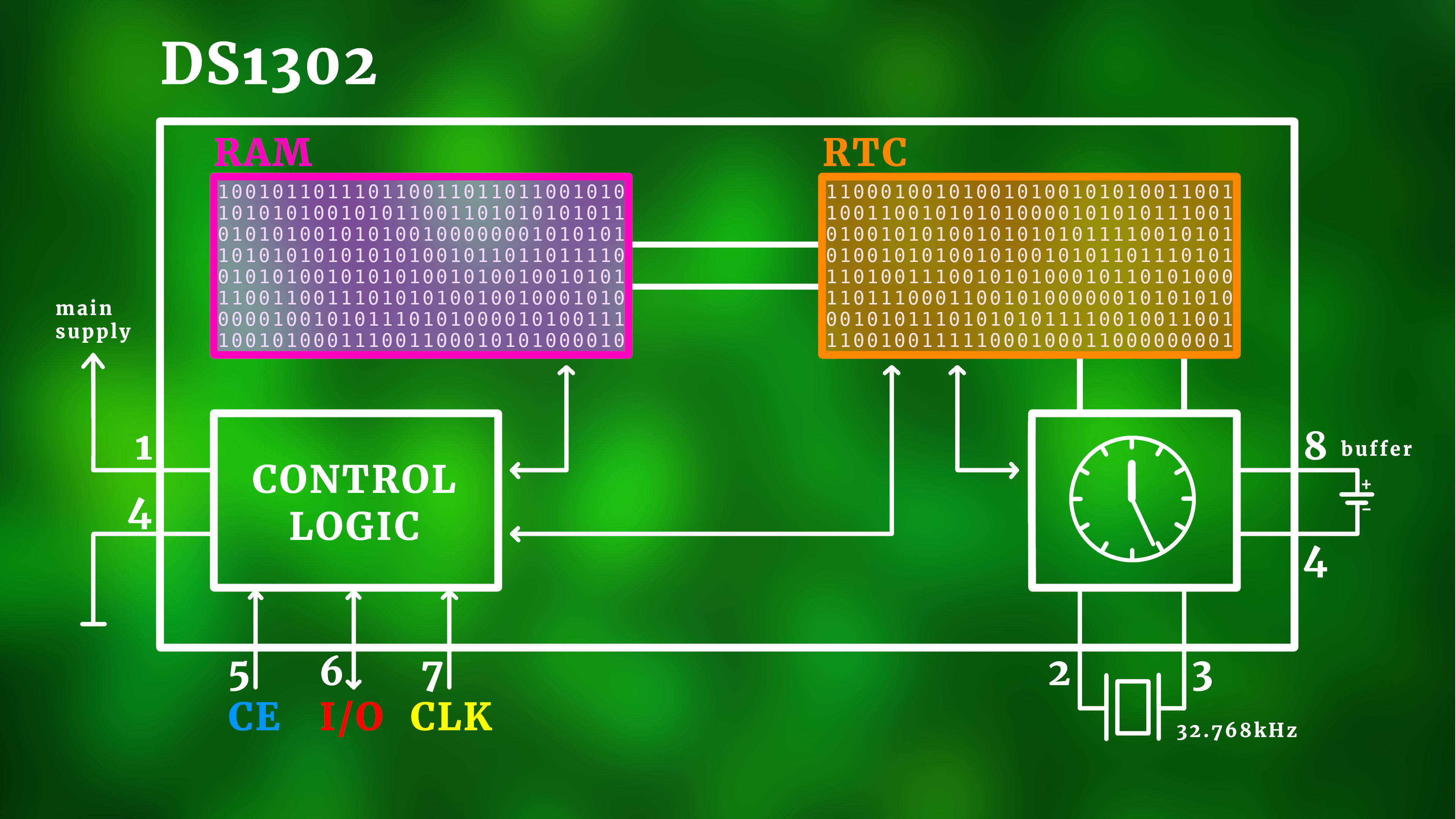
Looks complicated, but it's not that bad. Let's go through the different parts together.
- On the right you can see the internal clock. As soon as a battery is connected to the battery pins 4 (minus) and 8 (plus), the crystal at pins 2 and 3 starts resonating. The DS1302 uses this frequency of 32.768kHz and divides it by 215 to arrive at a stable 1Hz signal. Then, internally, it starts counting seconds, minutes, hours, and even days, months, and years. For the last part it has a built-in calendar that comes with leap year compensation up to the year 2100.
- This time information is stored in the RTC memory (orange) and as long as a buffer battery is connected this time information is continuously updated. It's important to know that every piece of time information is stored at a certain address in that memory.
- There is also an independent RAM module (purple) whose information is kept alive via the buffer battery, but it can only be updated externally. This is useful for storing settings and things like that, as we will see shortly. And again, every piece of information is stored at a certain address in that memory.
- The control logic is responsible for the communication with the outside world. It is only operational when the main supply at pins 1 (VDD) and pin 4 (ground) is turned on.
- The three pins CE, I/O, and CLK are all we need to talk to the DS1302 using a simple serial protocol. We'll talk about that in just one second. CE stands for “Chip Enable” and basically turns the DS1302's control logic on. CLK is a clock input pin, and I/O is a bidirectional data pin that can send out information or receive it.
By the way, if you want to learn more, you can always check out the DS1302 datasheet in the resources box.
So let's look at a simple example. Say we want to know the current value of the seconds. The DS1302 splits two-digit decimal numbers in ones and tens (which is sometimes also called binary-coded decimal system, or BCD for short). So let's learn how we can read the ones of the seconds.
The basic communication process between the DS1302 and the PIC microcontroller (or any other controller) is like a question-and-answer game. If you want to read out information, here is what you do:
- Turn the CE-pin on.
- Send a control byte from the PIC to the DS1302. This control byte basically means “DS1302, please tell me the ones of the seconds.”
- The DS1302 returns an answer byte, and that byte has the requested information inside of it.
- Turn the CE-pin off again.
Here is how to do this with the CE, CLK, and I/O pins:
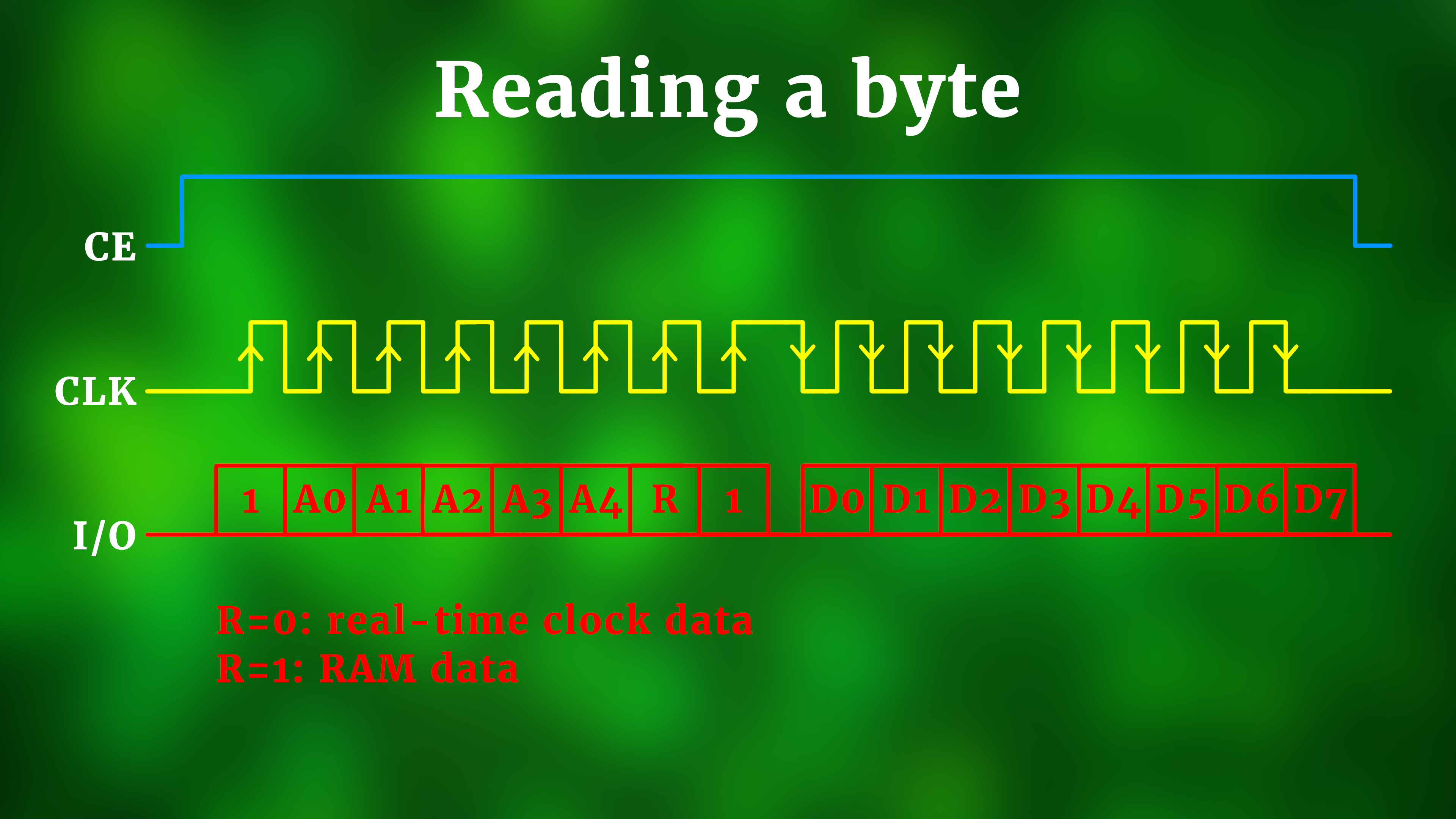
The first eight red boxes are the control byte. Each of the boxes can be either 1 or 0. A0–A4 encode the address where we are looking, and the bit R decides whether to look inside the RTC memory or the RAM.
When you look closely you see that we have to provide each bit of the control byte on the I/O pin, and after that pulse the CLK pin from 0 to 1. This means that data is transferred into the DS1302 at the so-called “rising edge” (and that's why I included the arrow on the rising part of the clock signal).
After having transmitted our eight bits of the control byte, it's time for the DS1302 to answer. The first bit of the response appears immediately after the last CLK pulse. This is why we say that the response is transferred with the so-called “falling edge” (which is why for the second part the arrows are on the falling edge of the clock signal). The eight bits D0–D7 then contain the answer to our control byte.
If you want to send information instead, it works like this:
- Turn the CE-pin on.
- Send a control byte from the PIC to the DS1302. This control byte basically means “Hey DS1302, I will send you the new ones of the seconds.”
- The DS1302 then waits for another control byte that contains the information.
- Turn the CE-pin off again.
And here is how it looks like for the CE, CLK, and I/O pins:
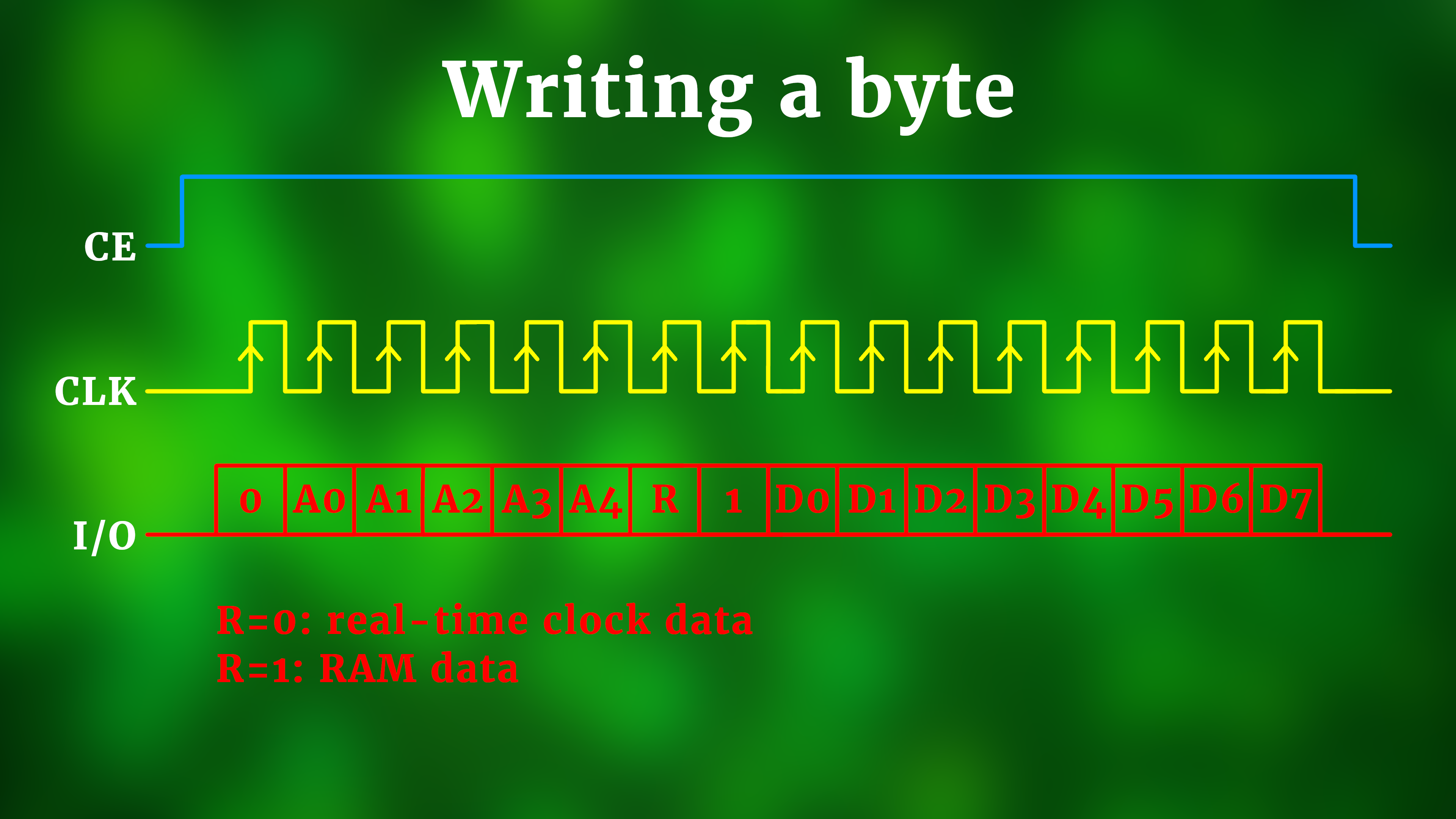
Comparing this with the reading procedure you can see that it's actually simpler: we are just sending two control bytes instead of one. The first one tells the DS1302 where we want to send the data (instead of where we want to look for it), and the second byte is then written to that location in either the RTC memory (when R=0) or into the RAM (when R=1).
So what exactly are the addresses? Here is the table from the datasheet. Orange is the time information in the RTC memory, and the purple part is the general purpose RAM.
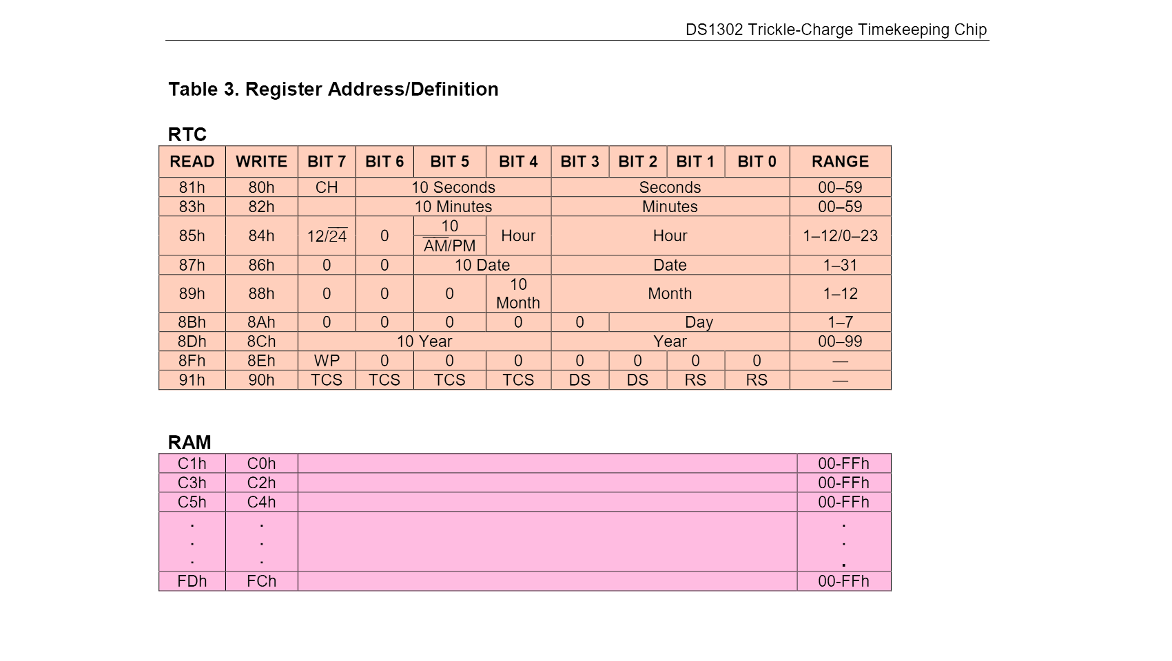
This table is a bit confusing, but it's actually super helpful. It does not tell us the addresses exactly, but it already tells us the entire command byte that we need for each action!
So, back to our original example: how do we read the ones of the seconds? By sending 0x81, which is a hexadecimal number, and in binary reads 0b10000001. And, sure enough, this matches to address 0 in the RTC memory :) And then the right columns tell us how the answer byte will look like, and the ones of the seconds are encoded in the bits 0-3.
And how do we write data? Say we want to set the ones of the second to 9, and the tens of the seconds to 2, so that the overall seconds read 29. Then, first, we have to send the command byte 0x80, which in binary is 0b10000000. So we are still at address 0 in the RTC memory, but now we want to write. And in order to send the 29 to the seconds we have to transmit the binary number 0b00101001, because 0b0010 is 2 and 0b1001 is 9 :) If you are lost with binary numbers you can check out my article on how to learn binary, I hope it helps :)
There is a lot more information stored in the DS1302, as you can see in the image above. In that case just look into the read and write columns of the table for the correct codes. And it works exactly the same way if you want to access the RAM: just look at the purple part of the diagram above. In that case the big columnb on the right is all empty because, well, it's completely up to you what you store in the eight bits of RAM at each address.
But yeah, that's how it works :) Now we have to program this into a microcontroller so that it can do that for us, all automatically. So let's go :)
Programming the PIC16F1455
Besides interfacing with he DS1302 RTC module, our PIC16F1455 has to do some other things as well. Here is a diagram of what the PIC has to do:
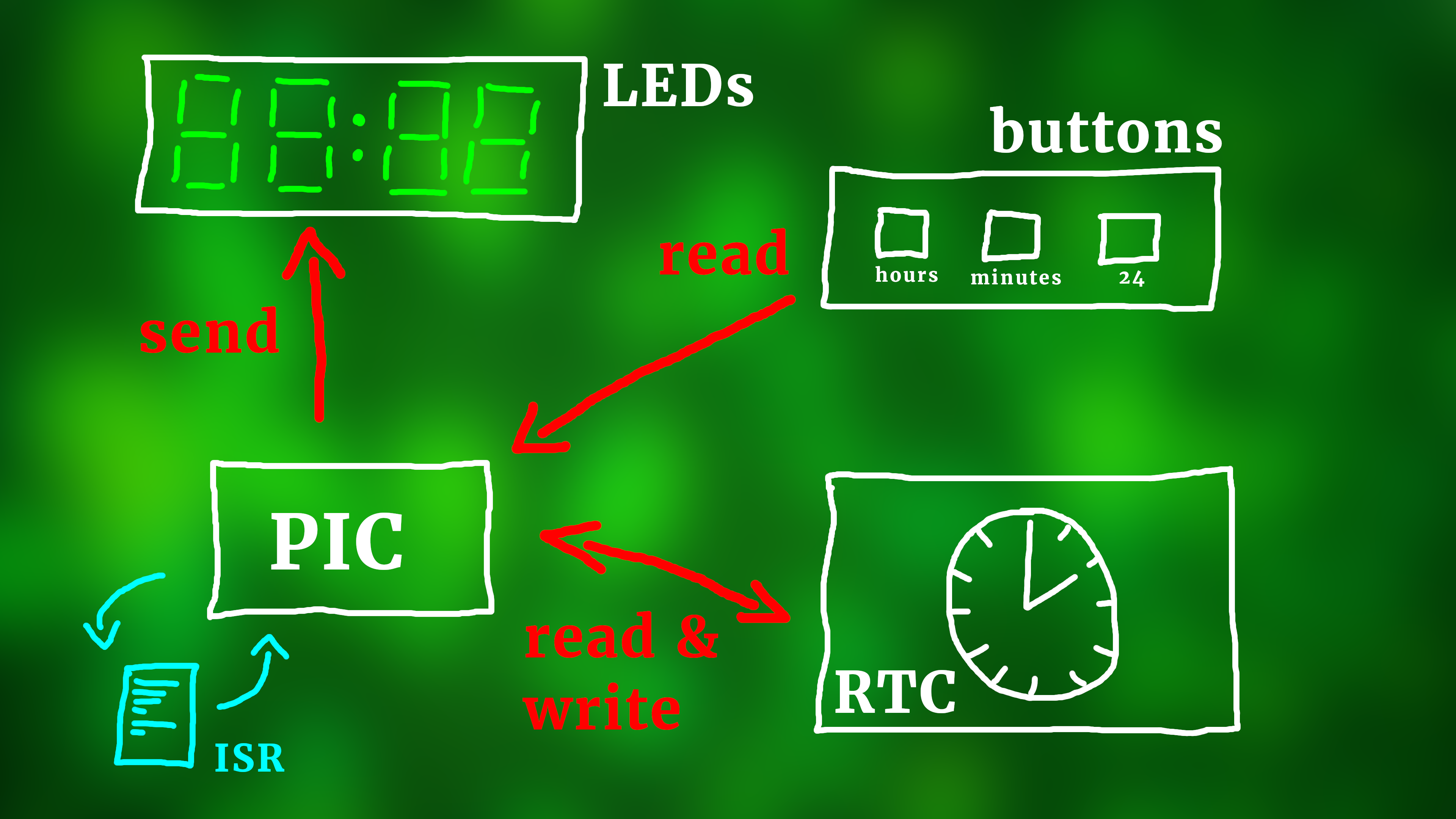
- It has to send the current time information to the LEDs.
- It has to react to the pressing of the pushbuttons.
- And it interfaces with the DS1302. Typically it only has to read the current time (since the DS1302 does that all for us), but in case the buttons are pressed to adjust the minutes or hours the PIC also has to send the new data to the DS1302 as well.
- And last, the ISR part at the bottom left stands for the so-called interrupt service routine. We use it here for a software debouncing of the pushbuttons, and if you want you can read more about it here.
Before we get into the nitty-gritty details of the source code, let me just say this: you don't need to understand everything in this part oof the article to build your own clock like this. Remember that the the source code is converted into a .hex-file, and the .hex-file has to be flashed onto the PIC16F1455 to tell it what to do. And we will describe in the next section how you can flash the PIC16F1455 using the .hex file you can download in the resources box :)
Alright, so let's look at the source code! You can find the code in its entirety in the appendix and you can also download the main.c file in the resources box. To keep our life simple, I divided the code in to three major parts:
- Reading data from the RTC.
- Displaying the data on the LEDs.
- Reacting to the pressing of buttons.
Before we get there I just want to mention some preliminary details. We are running the PIC16F455 at 4MHz with its internal oscillator, which is nice because it saves some external components. Right at the beginning we also define these arrays here:
// how are your segments connected to the TLC5916 driver?
// key:                       a  b  c  d  e  f  g  .
unsigned char seg_to_bit[] = {6, 5, 3, 2, 1, 7, 8, 4};

// useful array to convert 24-hour format into 12-hour mode
// key:                   0, 1, 2, 3, 4, 5, 6, 7, 8, 9, 10, 11, 12, 13, 14, 15, 16, 17, 18, 19, 20, 21, 22, 23
unsigned char get12[] = {12, 1, 2, 3, 4, 5, 6, 7, 8, 9, 10, 11, 12, 1,  2,  3,  4,  5,  6,  7,  8,  9,  10, 11};

// useful array to get the PM bit from 24-hour data
// key:                   0, 1, 2, 3, 4, 5, 6, 7, 8, 9, 10, 11, 12, 13, 14, 15, 16, 17, 18, 19, 20, 21, 22, 23
unsigned char getPM[] = { 0, 0, 0, 0, 0, 0, 0, 0, 0, 0, 0,  0,  1,  1,  1,  1,  1,  1,  1,  1,  1,  1,  1,  1};
The array seg_to_bit[] tells the controller which LED segment is connected to which output of the TLC5916, just as we already discussed in the TLC5916 tutorial. The arrays get12[] and getPM[] are just simple shortcuts that convert a 24-hour hours value into its 12 hour format (and tell you whether it is PM or not). You could just as well implement this with if-clauses, but I think this way it's a litte faster and uses less program memory.
And another thing, the interrupt service routine is called around 3900 times per second, and here is how it looks like:
// The interrupt service routine handles the blink animation of the dots
// as well as the debouncing of the three pushbuttons.
void __interrupt () isr (void) {

    // this is called abound 3900 times per second
	if (TMR0IF) {

        // blink animation
        BLINK_BUFFER += 1;
        if (seconds1 != seconds1old) {
            seconds1old = seconds1;
            BLINK_BUFFER = 0;
        }
        if (BLINK_BUFFER < 1950) {
            dots = 1;
        } else {
            dots = 0;
        }

        // debounce the buttons
        if ((!SW_HRS) && (SW_HRS_BUFFER > 0)) { SW_HRS_BUFFER -= 1; }
        if ((!SW_MIN) && (SW_MIN_BUFFER > 0)) { SW_MIN_BUFFER -= 1; }
        if ((!SW_24H) && (SW_24H_BUFFER > 0)) { SW_24H_BUFFER -= 1; }

		// reset interrupt flag
		TMR0IF = 0;

	}

}
It does two things: it animates the blinking animation of the LED dots in between the hours and minutes (and the minutes and seconds, if you're using six displays). I decided to put this in the interrupt service routine because this way it is guaranteed that the blinking is always of the same duration. And second, in line 320, we debounce the pushbuttons as we learned earlier.
Okay, with that out of the way, let's have a look at parts 1, 2, and 3.
Part 1: Reading data from the RTC.
This part contains six similar operations consisting of reading the ones and tens of the seconds, minutes, and hours. Here is how to read the seconds:
        // ********************************************************************
        // PART 1: READ DATA FROM REAL-TIME CLOCK

        // retrieve seconds
        RTC_CE = 1;
        sendRTC(0x81);
        tmp = getRTC();
        RTC_CE = 0;
        seconds10 = (tmp & 0b01110000) >> 4;
        seconds1  = tmp & 0b00001111;
The function sendRTC() is used to send out the command bytes to the DS1302 as we learned above, and the function getRTC in turn, you guessed it, returns the answer which is then stored in the variable tmp. In lines 127-128 we then split the result up into the tens and ones of the seconds. For the minutes it works exactly the same (only the command byte is different):
        // retrieve minutes
        RTC_CE = 1;
        sendRTC(0x83);
        tmp = getRTC();
        RTC_CE = 0;
        minutes10 = (tmp & 0b01110000) >> 4;
        minutes1  = tmp & 0b00001111;
For the hours it is slightly different because the DS1302 can run both in 24-hour mode and AM/PM mode. When writing the code I decided that it was silly to keep switching the DS1302 between modes, so I implemented the conversion between 24-hour mode and AM/PM mode manually and had the DS1302 run in 24-hour mode always. But we have to check after reading the hour information whether the AM/PM mode was initially set. This can happen by accident when you first use the DS1302. For this reason the hours part is a bit more complicated:
        // retrieve hours
        RTC_CE = 1;
        sendRTC(0x85);
        tmp = getRTC();
        RTC_CE = 0;

        // Is the mode set to AM/PM?
        if (tmp >> 7) {

            // Set mode to 24-hour mode.
            // (Conversion to 12-hour mode, if required, is done by us in the code.)
            RTC_CE = 1;
            sendRTC(0x84);
            sendRTC(1<<7);
            RTC_CE = 0;

            // Re-read the hours again, this time in the proper 24-hour format.
            RTC_CE = 1;
            sendRTC(0x85);
            tmp = getRTC();
            RTC_CE = 0;

        }
In line 138-142 we just read out the hour information, but in line 145 we check whether the mode is set internally to AM/PM. If so, we set the mode back to the 24-hour mode (lines 149-152) and then we just re-read the hours again in lines 155-158. After that we can extract the tens of the hours and the ones:
        // extract tens and ones for the hours
        hours10 = (tmp & 0b00110000) >> 4;
        hours1  = tmp & 0b00001111;

        // generate the 24-hour hours value
        hours = 10*hours10 + hours1;

        // find current mode
        RTC_CE = 1;
        sendRTC(0xc1);
        mode24 = getRTC();
        RTC_CE = 0;
This part of the code could be somewhat improved, arguably. I use the variable hours as the full 24-hour time information, and line 167 is not very efficient because an explicit multiplication takes a lot of resources. But it works, and our program is not very long. Then, in lines 170-173, we determine what mode the clock is currently in.
Important: Here we are reading from the custom general purpose RAM part and not from the RTC module directly. We are kind of implementing our own AM/PM conversion that way. It may sound a bit contrived, but I like this approach because that way we can let the DS1302 stay in 24-hour mode forever and don't need to switch it. And, additionally, we also learn how to use the DS1302's included general purpose RAM as well.
And that's all we need for Part 1!
Part 2: Displaying the data on the LEDs.
For the seconds and minutes this is pretty straightforward:
        // ********************************************************************
        // PART 2: DISPLAY DATA ON LEDs

        // send seconds (and include the blinking dots)
        sendValue(convertNumberToPattern(seconds1));
        sendValue(convertNumberToPattern(seconds10) | (dots << 0));

        // send minutes (and include the blinking dot)
        sendValue(convertNumberToPattern(minutes1)  | (dots << 0));
        sendValue(convertNumberToPattern(minutes10) | (dots << 0));
We already learned about the functions sendValue() and convertNumberToPattern() in the TLC5916 tutorial, so I won't repeat it here. Basically we are just sending out the ones and tens of the seconds, and then the ones and tens of the minutes. We are doing it backwards because the data goes into the leftmost display first, so it has to travel all the way to the right. In other words, we have to send the hours last.
But what is that weird | (dots << 0) doing there? The variable dots equals 1 whenever the blinking dots are turned on, so this just takes care of the blinking animation. Looking into the convertNumberToPattern function we see this:
// This function converts a number into the 7-segment pattern.
unsigned char convertNumberToPattern (unsigned char number) {

    // what is the number?
    switch (number) {

        // numbers       abcdefg.
        case 0: return 0b11111100;
		...
Look at line 407. It shows us that in our conventions the decimal point is located at bit 0. This is why we have the strange << 0 in the code, which doesn't do anything. I decided to include it so that I will remember to change it to something else if I ever mode the location of the decimal point.
And then, depending on whether we are in the 24-hour or AM/PM mode we can finally send out the data for the hours.
        // 24-hour mode
        if (mode24) {

            // send hours (and include the blinking dot)
            sendValue(convertNumberToPattern(hours1) | (dots << 0));
            sendValue(convertNumberToPattern(hours10));

        // 12-hour mode
        } else {

            // send hours (and include the blinking dot as well as the PM indicator)
            tmp = get12[hours] % 10;
            sendValue(convertNumberToPattern(tmp) | (dots << 0));
            tmp = get12[hours] / 10;
            sendValue(convertNumberToPattern(tmp) | getPM[hours]);

        }
And here we of course also have to include the blinking dots, just as before. And finally we need to tell the TLC5916 registers to display the new data:
        // update all data in the registers
        LE = 1;
        LE = 0;
And that's all for the display part.
Part 3: Reacting to the pressing of buttons.
Whenever the user presses the hours or minutes button, we have to increase their values and reset them if they exceed 23 or 59, respectively. Also, for convenience, we reset the seconds every time the user adjusts the time. This makes it a lot easier for the user to set the clock accurately.
Here is how the part looks like for the hours:
        // ********************************************************************
        // PART 3: REACT TO USER INPUT,
        // AND UPDATE REAL-TIME CLOCK DATA IF NECESSARY

        // has the HOUR button been pressed?
        if ((SW_HRS) && (SW_HRS_BUFFER == 0)) {

            // increase hours
            hours++;
            if (hours > 23) {
                hours = 0;
            }

            // calculate new ones and tens
            hours1 = hours % 10;
            hours10 = hours / 10;

            // update hours in real-time clock
            RTC_CE = 1;
            sendRTC(0x84);
            sendRTC( (hours10 << 4) | hours1 );
            RTC_CE = 0;

            // reset seconds
            RTC_CE = 1;
            sendRTC(0x80);
            sendRTC(0);
            RTC_CE = 0;

            // reset debounce variable
            SW_HRS_BUFFER = 50;

        }
Let's go through the code step by step:
- Line 219 makes sure that the button is pressed and that it's also debounced properly.
- Lines 222-225 increase the hours and implement the proper reset.
- Then we can calculate the new tens and ones in lines 228-229.
- Updating the hours information is done in lines 232-235. You can see how we shift the tens of the hours to the left by four bits, and then add the ones of the hours, so that everything is in the correct position of the command byte. And then we can send it to the DS1302.
- As I said above, we also reset the seconds, and that is done in lines 238-241.
- And last, we have to tell the controller that the hours button was pushed, so we set the buffer variable
SW_HRS_BUFFERto 100 for a software debouncing.
And then the same step is basically repeated for the minutes:
        // has the MINUTE button been pressed?
        if ((SW_MIN) && (SW_MIN_BUFFER == 0)) {

             // increase minutes
            minutes1++;
            if (minutes1 > 9) {
                minutes1 = 0;
                minutes10 += 1;
                if (minutes10 > 5) {
                    minutes10 = 0;
                }
            }

            // update minutes in RTC
            RTC_CE = 1;
            sendRTC(0x82);
            sendRTC( (minutes10 << 4) | minutes1 );
            RTC_CE = 0;

            // reset seconds
            RTC_CE = 1;
            sendRTC(0x80);
            sendRTC(0);
            RTC_CE = 0;

            // reset debounce variable
            SW_MIN_BUFFER = 50;

        }
The only difference to the hours case is that the reset conditions in lines 252-259 are slightly different, because minutes reset at 60 and not at 24.
Reacting to the 24-hour button is very different, though. This is what we do:
        // has the 24-HOUR button been pressed?
        if ((SW_24H) && (SW_24H_BUFFER == 0)) {

            // increase brightness mode
            mode24 = 1 - mode24;

            // store new mode
            RTC_CE = 1;
            sendRTC(0xc0);
            sendRTC(mode24);
            RTC_CE = 0;

            // reset debounce variable
            SW_24H_BUFFER = 100;

        }
Here is what happens:
- In line 282 we simply invert the mode.
- In lines 285-288 we save the new mode in the general purpose RAM.
- And, similar to before, in line 291 we reset the debounce buffer for the 24-hour button.
And that's it!
The sendRTC() and getRTC() functions.
By now we understand almost everything, except for the precise way we send out the data and receive the data back from the DS1302. So, if you're still awake, let's have one final look at the two functions that implement the communication with the DS1302.
The sendRTC() function sends out a byte to the DS1302. This is how it looks like:
// This function sends the byte "value" to the RTC.
void sendRTC (unsigned char value) {

    // set data port as output
    TRISC1 = 0;

    // auxiliary index variable
	char n = 0;

    // loop over all eight bits
	for (n = 0; n < 8; n++) {
        RTC_IO = (value >> n) & 1;
        CLK = 1;
        CLK = 0;
    }

}
If you recall the TLC5916 tutorial you will realize that this function is pretty much identical in its idea to the sendValue() function we used before. We simply cycle over all bits in the for-loop in lines 342-346 and set the IO-pin to the current bit value.
The only important difference is this: the pin RC1, which we use as our IO pin, is bidirectional. Here we need it to send data, so we need to turn it into a digital output first (line 336). Also, since the DS1302 serial protocol for sending data works on the rising edge, we need to set the IO pin to the current bit first, and only afterwards pulse the clock pin to 1 and back to 0.
The getRTC() function, on the other side, looks like this:
// This function receives a byte from the RTC
// and returns it to the program.
unsigned char getRTC (void) {

    // set data port as input
    TRISC1 = 1;

    // dummy variables
    unsigned char value = 0;
    char n = 0;

    // collect all eight bits
    for (n = 0; n < 8; n++) {
        value |= (RTC_IO << n);
        CLK = 1;
        CLK = 0;
    }
    return value;

}
First, we need to make sure that RC1 is now an input (line 355). And then we cycle again through the eight bits of the DS1302's answer byte. But there is one important difference: we read the current bit before applying another clock pulse, because the DS1302's answering protocol works on the falling edge.
I am sure there is more to say about the program, and if you are confused about anything feel free to reach out on social media. But that's all for now, and let's get towards flashing this program onto the PIC16F1455.
Flashing the PIC16F1455
The starting point for flashing is the ds3202.hex file that you can either get from compiling the source code from the previous section yourself, or from downloading it from the resources box.
This is the little schematic we need to build to flash the .hex file onto the PIC16F1455:
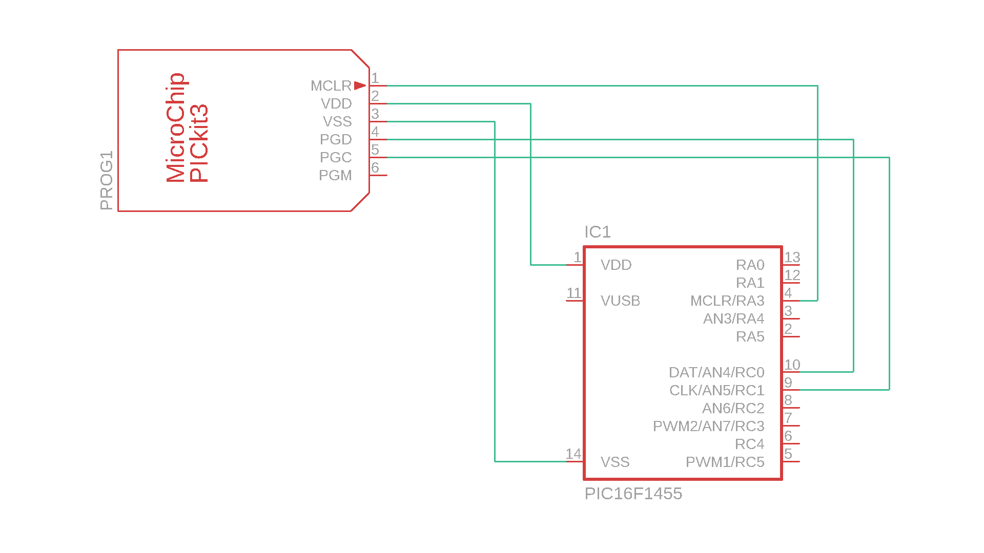
And this is how it looks like in real life:
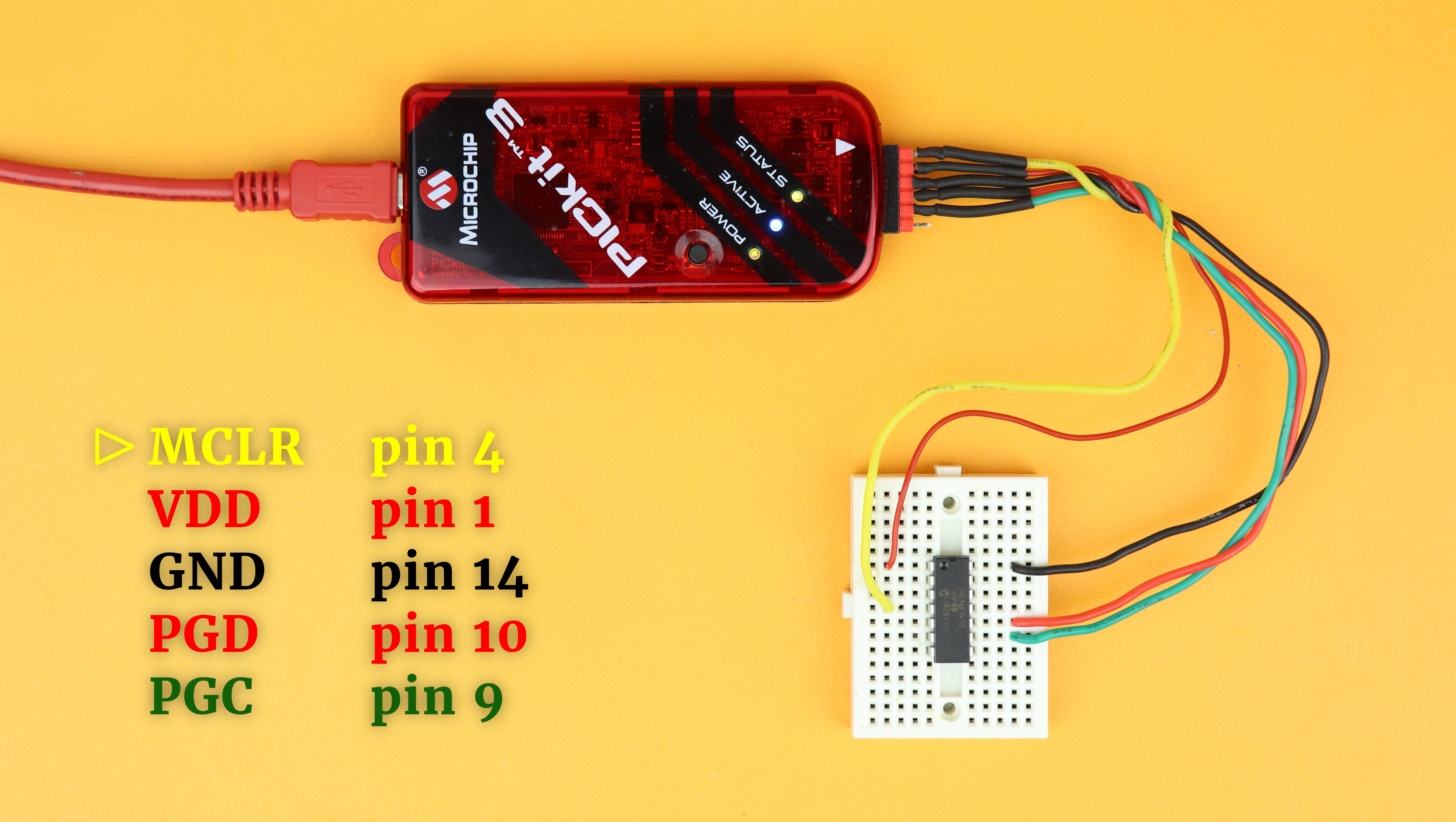
Make sure that you don't accidentally flip the orientation of the PICkit3. The wire at pin 1 of the PICkit3 (the one marked with the triangle) is MCLR. Then connect the PICkit3 to your computer via USB.
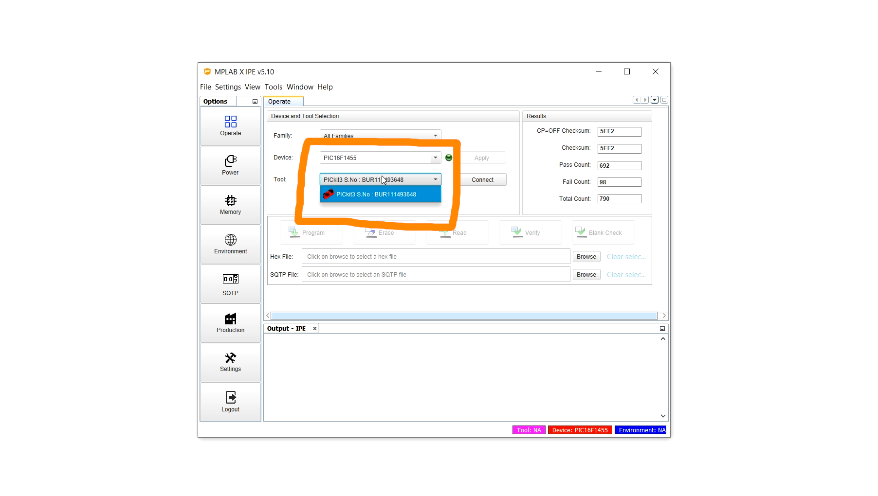
Next, open the freely available MPLAB X IPE, the programming environment, and select the PIC16F1455 as the device and the PICkit3 as the tool:
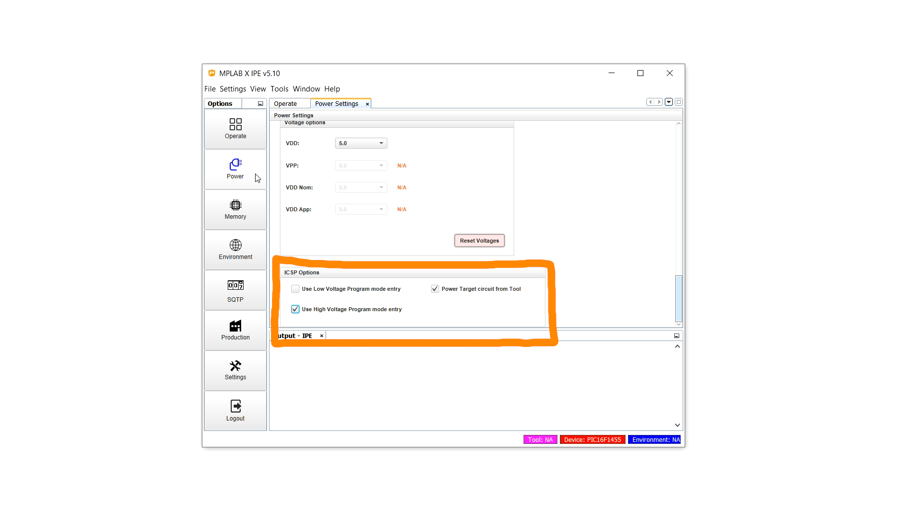
Click on Power on the left-hand side and select Power Target circuit from Tool as well as Use High Voltage Program mode entry:
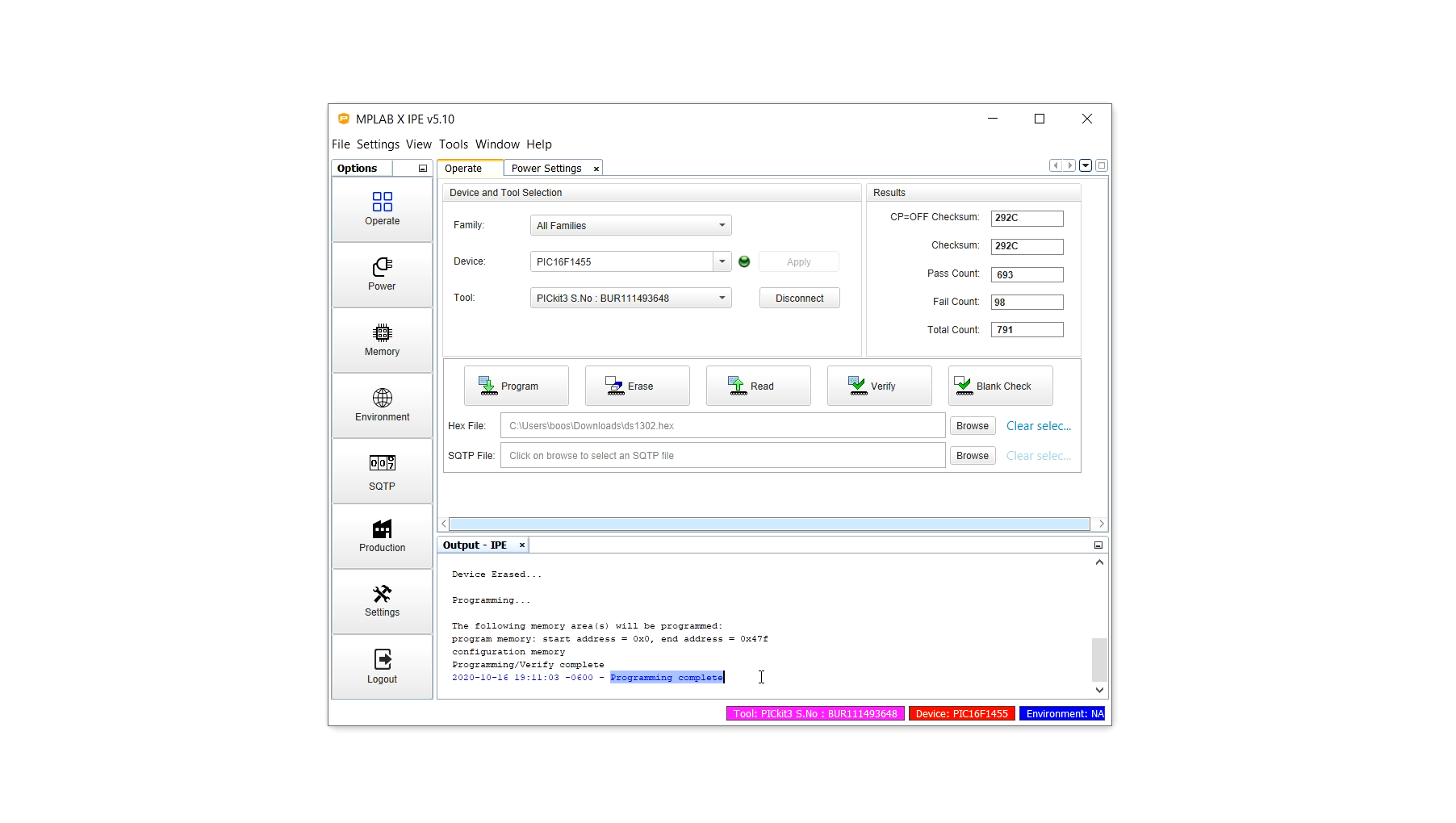
Then go back to the Operate menu and load the .hex file by clicking on Browse. Then click on Program (and at this point a confirmation dialog may pop up, which you can simply confirm), and after a while you should see a success message: Programming complete.
The .hex file is now on the PIC16F1455, congratulations! Remove the PIC16F1455 from the breadboard, set it aside, and now we can begin building the circuit!
Construction
So let's go ahead and build the circuit together, step by step :)
Before we start building things on the breadboard we have to prepare the 7-segment LED displays. The idea is that we can plug them right on top of the TLC5916 driver ICs, exactly as in the TLC5916 tutorial, by presoldering some longer wires th them. This is how the final product looks like:
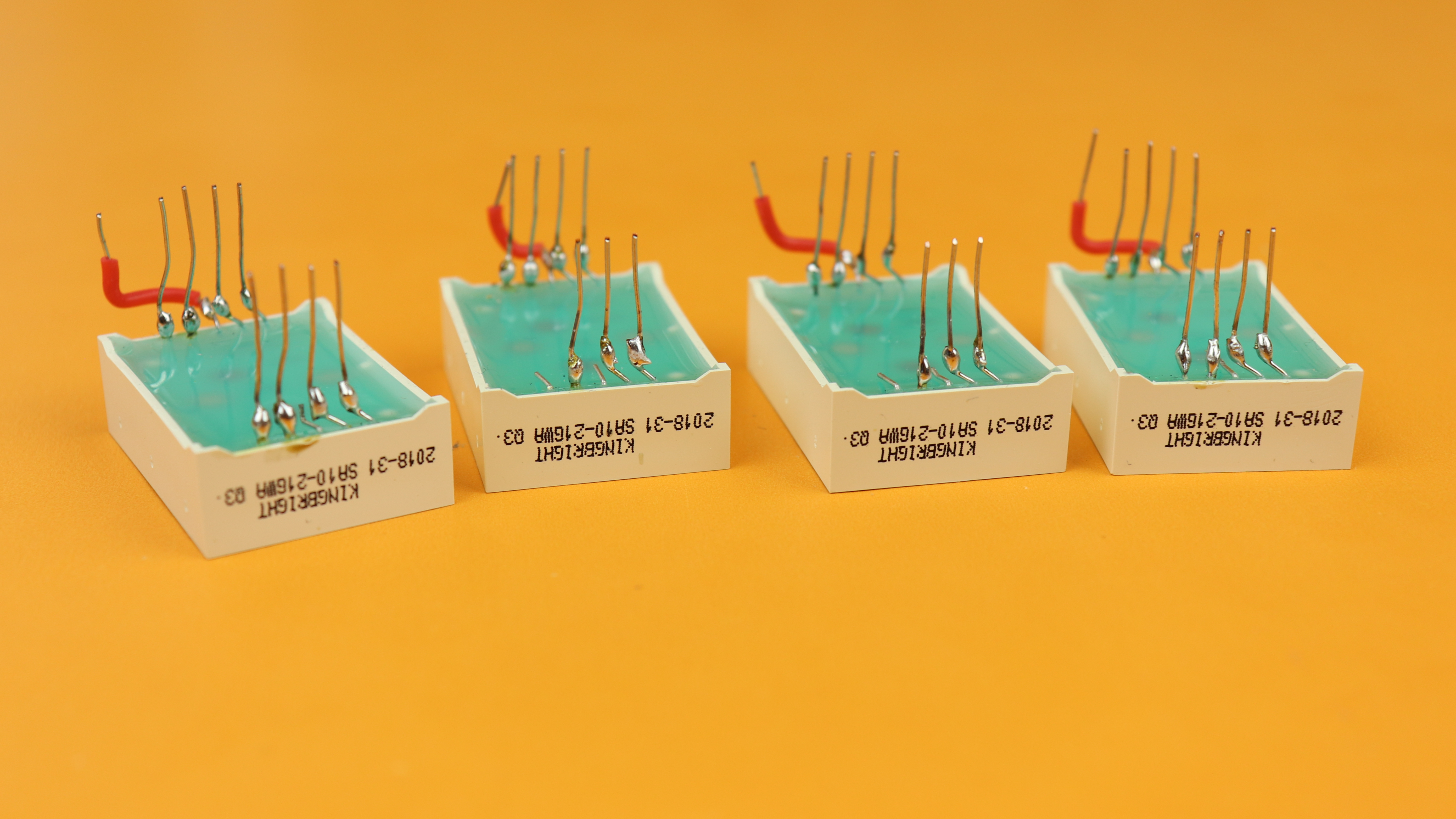
And if you want to learn how to do this, check out the TLC5916 tutorial for all the details :) And no worries, if you don't want to solder, you can always use Dupont-style wires for the connections instead. It won't be as compact, but it will still work :)
And now it's finally time to turn to the breadboard!
-
-
Step 1
Place the 830-pin breadboard in front of you with row 1 facing to the left :)
-
-
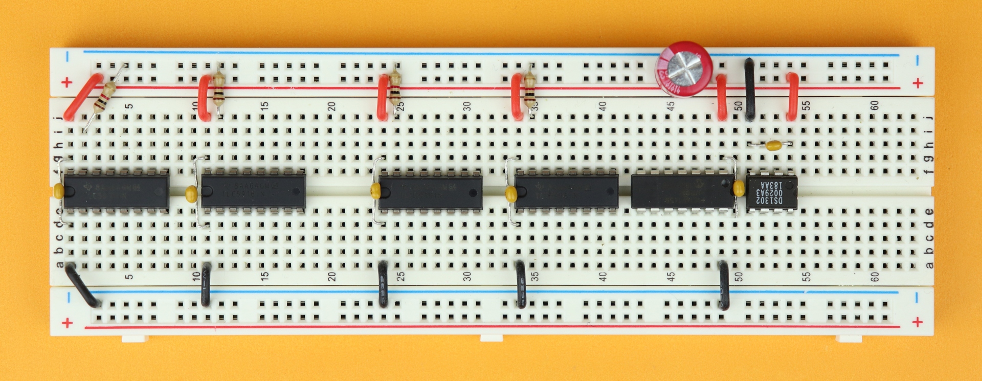
Step 2
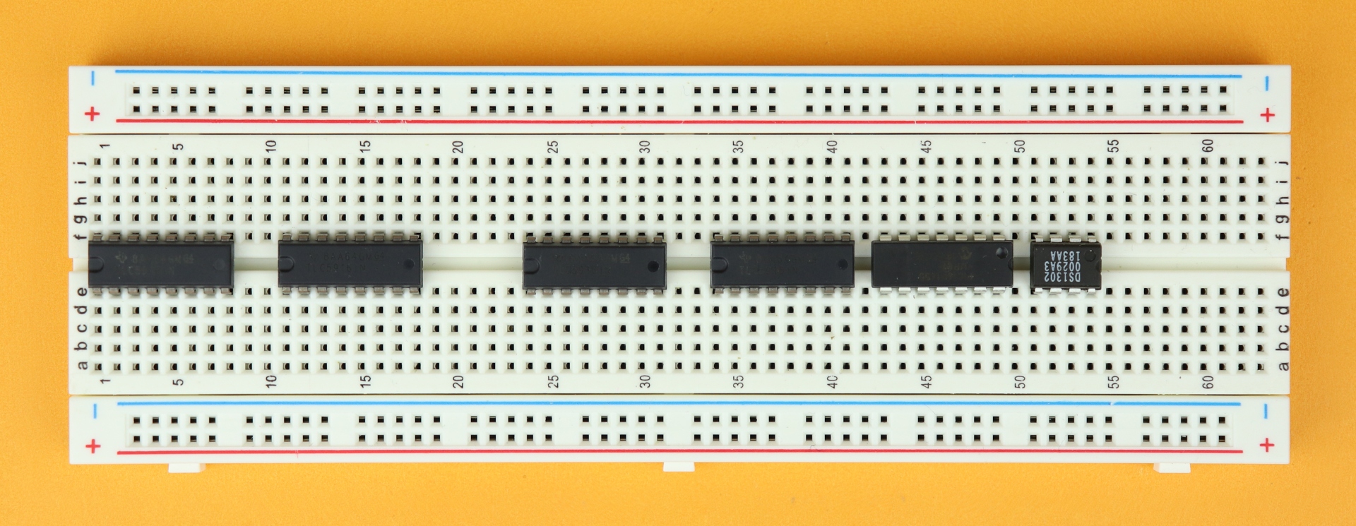
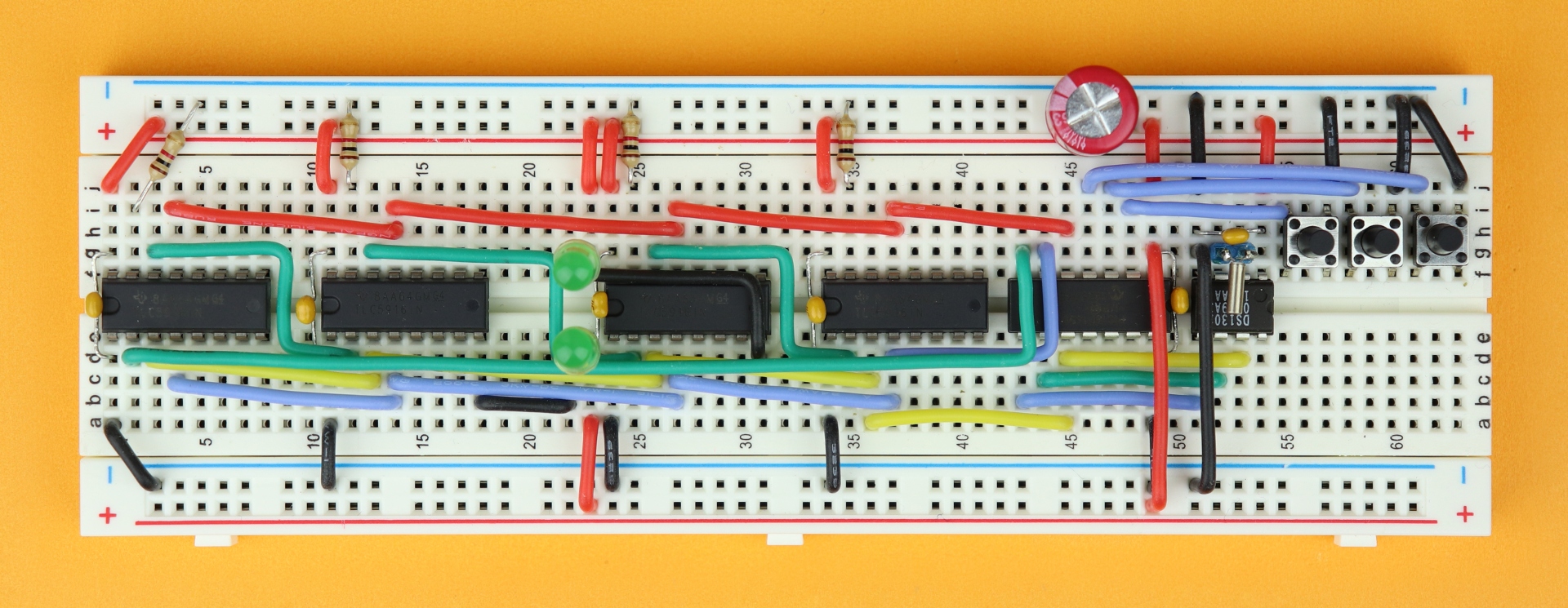
Insert the four TLC5916 driver ICs in rows 1, 11, 24, and 34. Make sure their notches point to the left. Then insert the PIC16F1455 in row 43, and make sure its notch points to the right. And last, insert the DS1302 real-time clock IC in row 51 and also make sure its notch points to the right.
-
-
Step 3
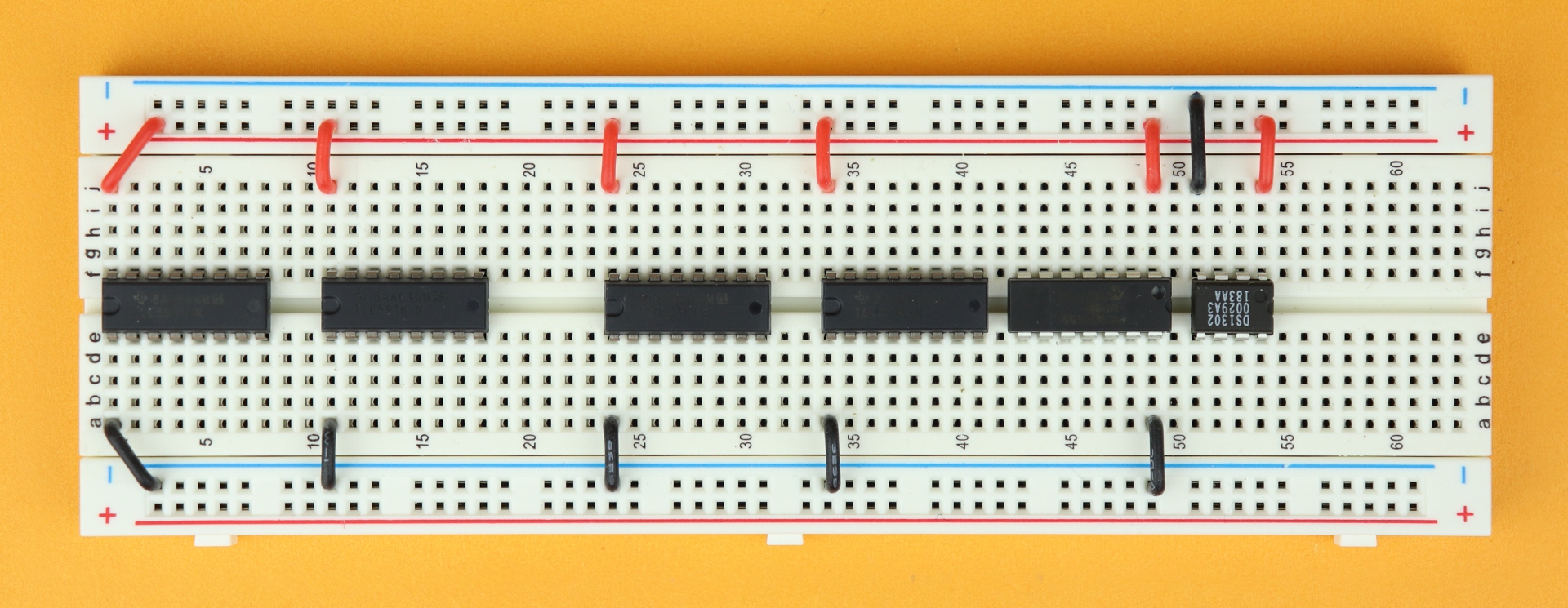
Now it's time to connect power. For the TLC5916 driver ICs connect their pin 1 to the ground rail (black wires) and their pin 16 to the VDD rail (red wires). For the PIC16F1455 it's exactly the other way around: its pin 1 is connected to VDD (red wire) and its pin 14 (black wire) is connected to ground. And last, for the DS1302, connect pin 1 to VDD and pin 4 to ground.
-
-
Step 4
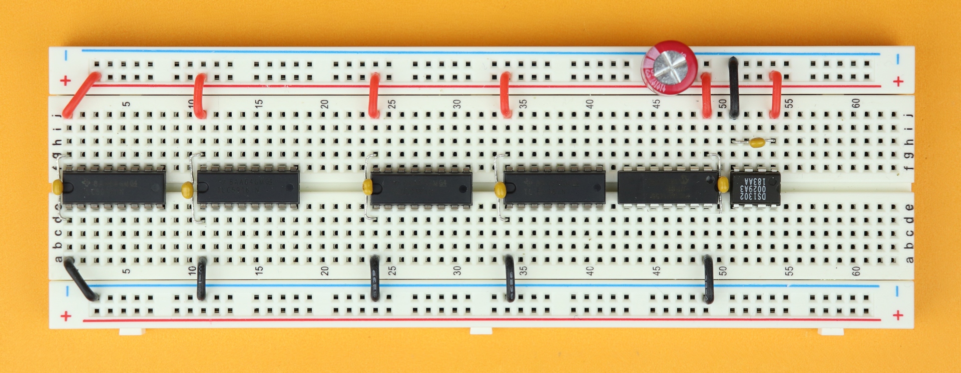
Next, insert the bypass capacitors C1–C6. C1–C4 go directly between pins 1 and 16 of the TLC5916 driver ICs, and C5 goes between pins 14 and 1 of the PIC16F1455 in a similar way. And C6 is placed between pins 1 and 4 of the DS1302.
The bulk capacitor C7 can be placed anywhere in the breadboard, but I recommend this position as the rest of the breadboard will become quite crowded later. Connect its positive terminal to the VDD power rail and its negative terminal to the ground power rail.
Important: the negative terminal of C7 is highlighted by a big minus sign, and make sure you get the polarity right. The capacitors C1–C6 are not polarity sensitive and can be plugged in either way.
-
-
Step 5
Plug in the four 1kΩ resistors R1–R4 from pin 15 of each TLC5916 into the ground rail.
-
-
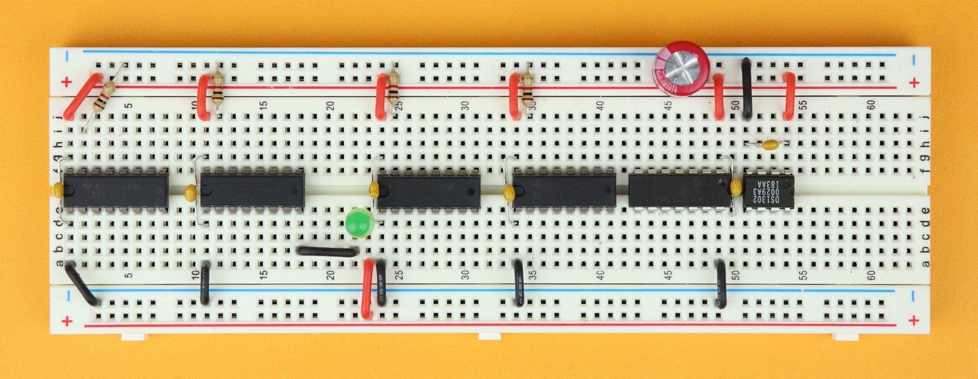
Step 6
Insert LED5 in rows 22 and 23. It's a bit hard to see from this perspective, but the LED's cathode is plugged into row 22 and its anode goes into row 23. Then connect the cathode in row 22 to pin 8 of IC2, and connect its anode in row 23 to the VDD rail.
-
-
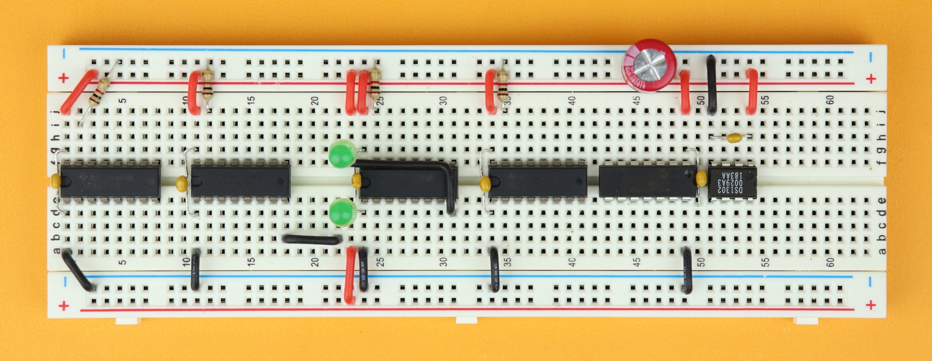
Step 7
Insert LED6 in rows 22 and 23, but now on the upper part of the breadboard. Connect its anode at row 23 to the VDD rail with the red wire, and connect its cathode in row 22 to pin 8 of IC3.
-
-
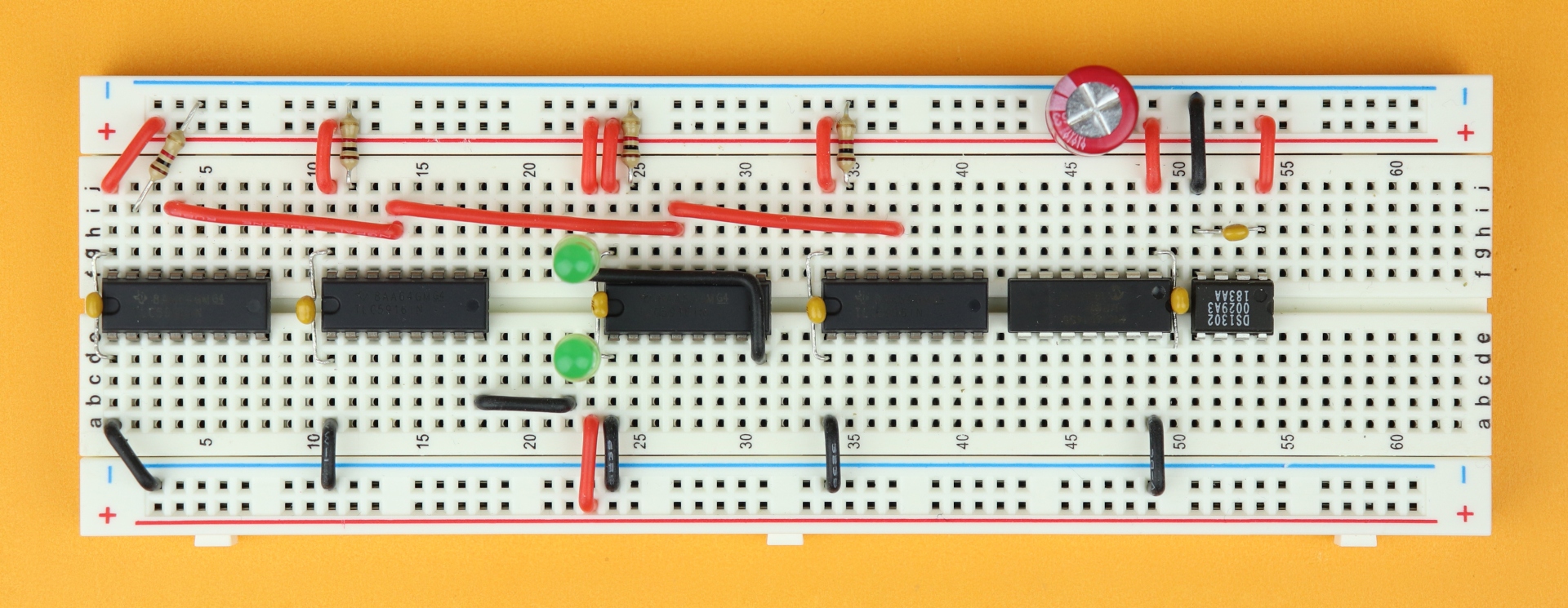
Step 8
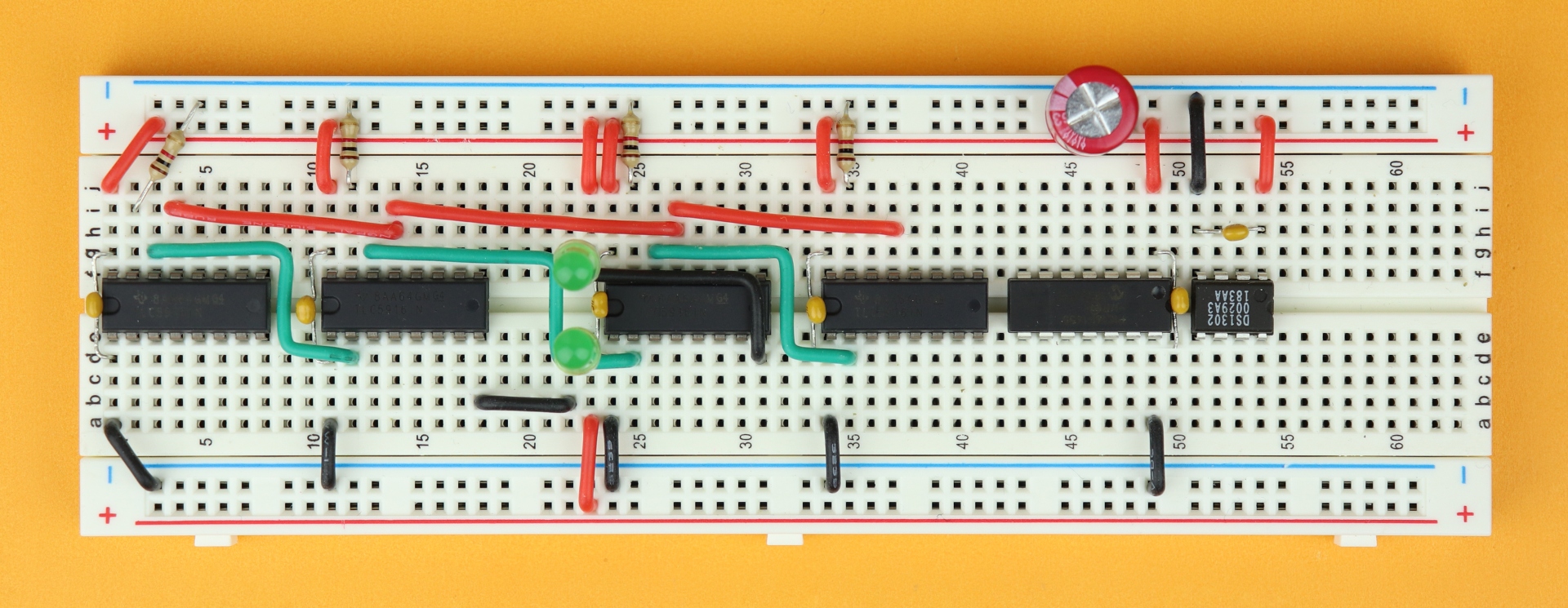
Now it's time to start working on the signal bus. Connect all /OE inputs at pin 13 of the TLC5916 in parallel. I connected the wires in a staggered way so that it looks nice.
-
-
Step 9
Then, connect each SDO output (pin 14) to the SDI input (at pin 2) of the next TLC5916.
-
-
Step 10
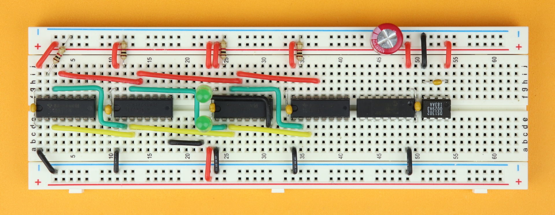
The clock inputs of each TLC5916 at pin 3 are also connected in parallel, and I like to use the staggered wiring again (as well as different colors).
-
-
Step 11
Then, connect all LE pins (pin 4) in parallel as well.
-
-
Step 12
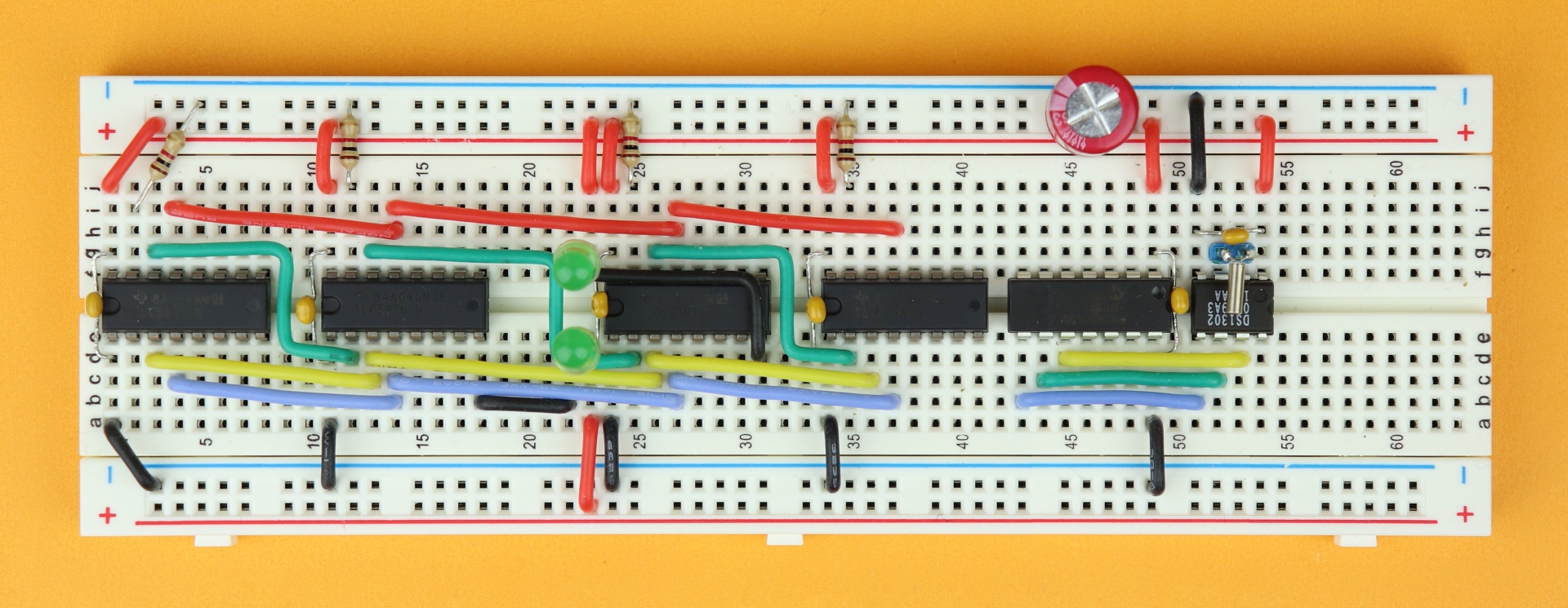
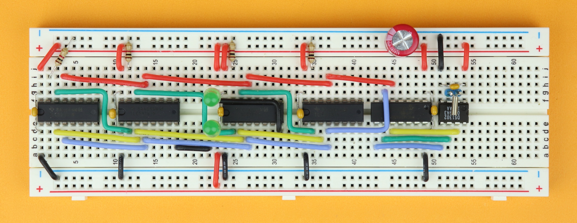
And now we can turn our attention to the real-time clock. Insert the 32.768kHz cystal between pins 2 and 3 of the DS1302 and make sure it is as close to the chip as possible. I actually soldered my crystal to a small 2-pin header so that it can be easily inserted into the breadboard, its wires are very thin and the crystal is tiny!
Then, connect the DS1302's control pins to the PIC16F1455: connect CLK (pin 7) of the DS1302 to RC0 (pin 10) of the PIC16F1455, IO of the DS1302 (pin 6) to RC1 (pin 9) of the PIC16F1455, and CE (pin 5) of the DS1302 to RC2 (pin 8) of the PIC1455.
-
-
Step 13
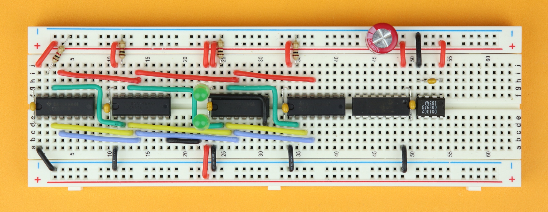
Now, connect the /OE inputs to pin 5 of the PIC16F1455 (in red), and then connect the LE inputs to pin 6 (in blue).
-
-
Step 14
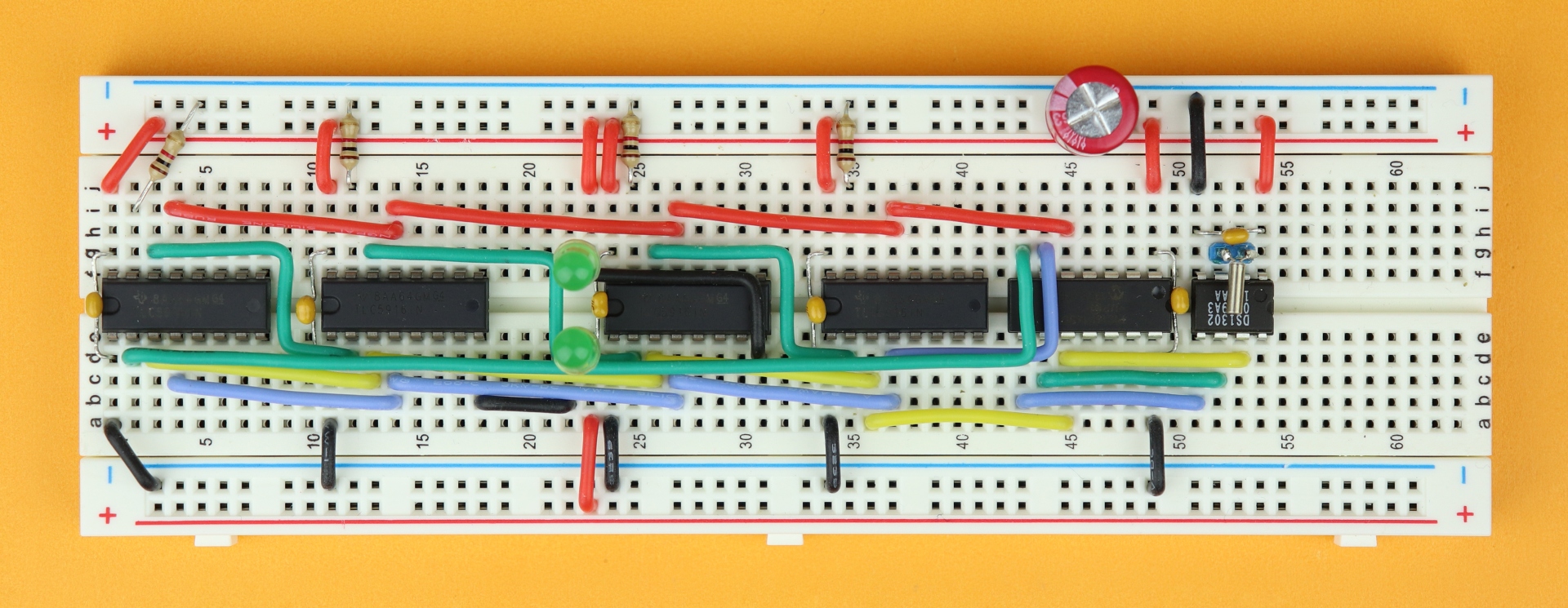
Next, connect the SDI input at pin 2 of the leftmost TLC5916 driver to pin 7 of the PIC16F1455. This wire (green) is quite long, and I tried to bend it nicely so it fits snugly under the LED on its way.
Then, finally, connect the clock inputs to pin 10 of the PIC16F1455 (in yellow).
-
-
Step 15
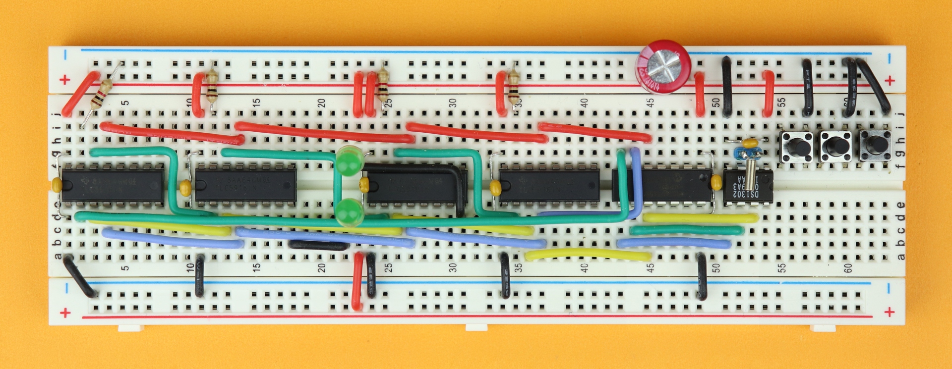
Now insert the three pushbuttons in rows 55, 58, and 61, and connect their right terminals in rows 57, 60, and 63 to the ground rail.
-
-
Step 16
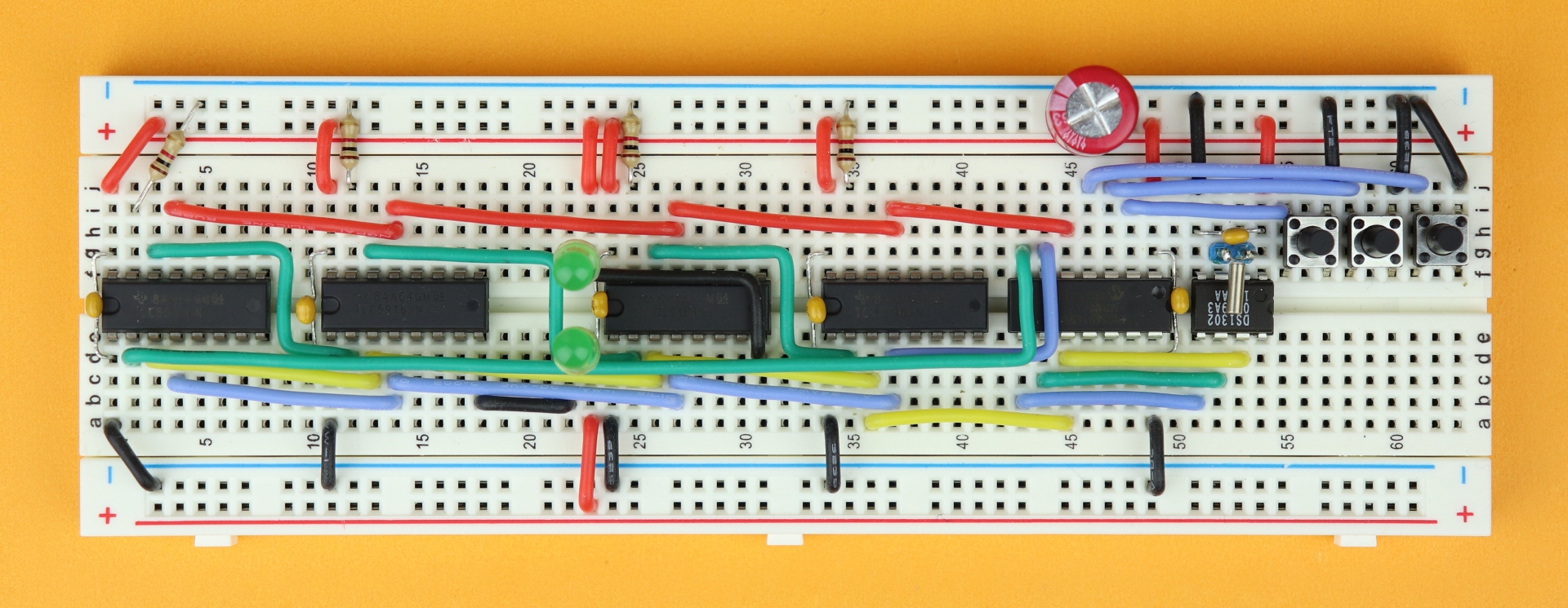
And then, connect the other terminals to the PIC16F1455: S1's left terminal is connected to pin 2 of the PIC16F1455, S2's left terminal goes to pin 3, and S3's left terminal is wired up with pin 4.
Because there is not a lot of space I inserted these wires into the same hole as one of the terminals of their corresponding switch. This can be a bit finicky, but I think it's worth it because it really saves a lot of space.
-
-
Step 17
And now we can finally connect the two power rails on either side of the breadboard. Connect pin 1 of the PIC16F1455 all the way down into the positive power rail, and connect pin 4 of the DS1302 to the ground rail.
-
-
Step 18
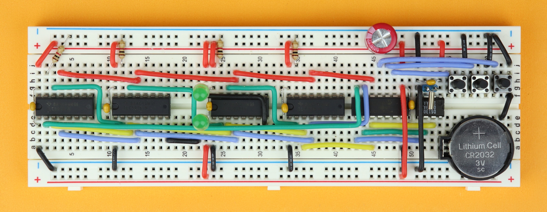
Then it's time to insert the battery holder. Insert the CR2032 coin cell, and make sure that its positive terminal points up, facing you (like in the picture). The positive terminal of the battery holder is the square-ish side. Plug the battery holder into the breadboard such that the positive terminal is connected to row 54. This way, the battery's positive terminal is connected to pin 8 of the DS1302, where it should be. On the other side, connect the negative terminal (here in row 62) to row 63 on the upper side of the breadboard, such that it is connected to the ground rail.
-
-
Step 19
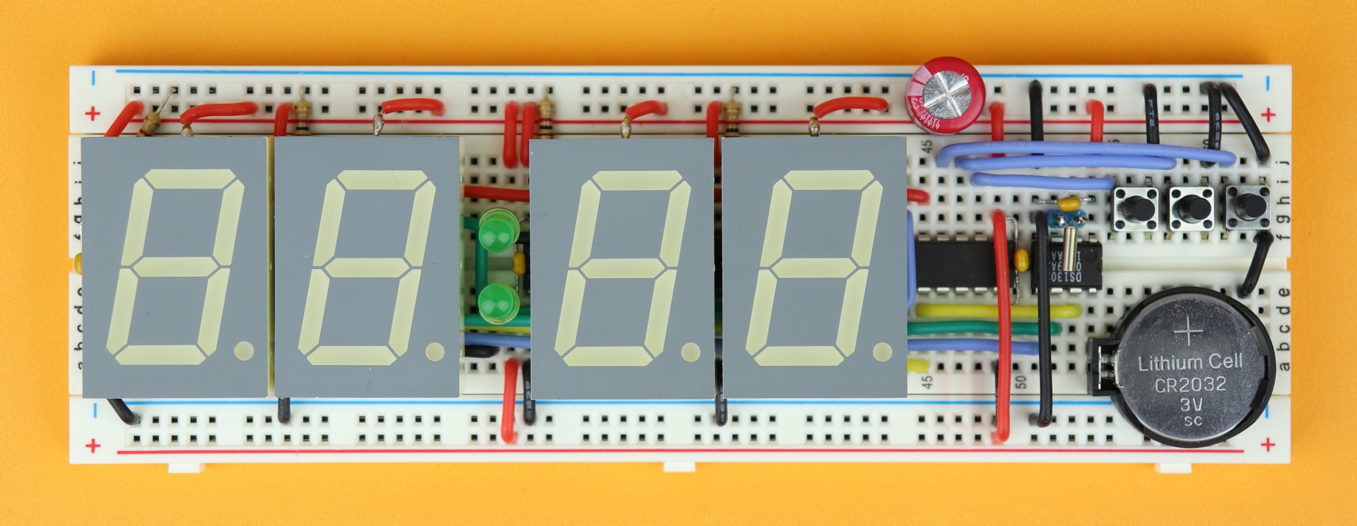
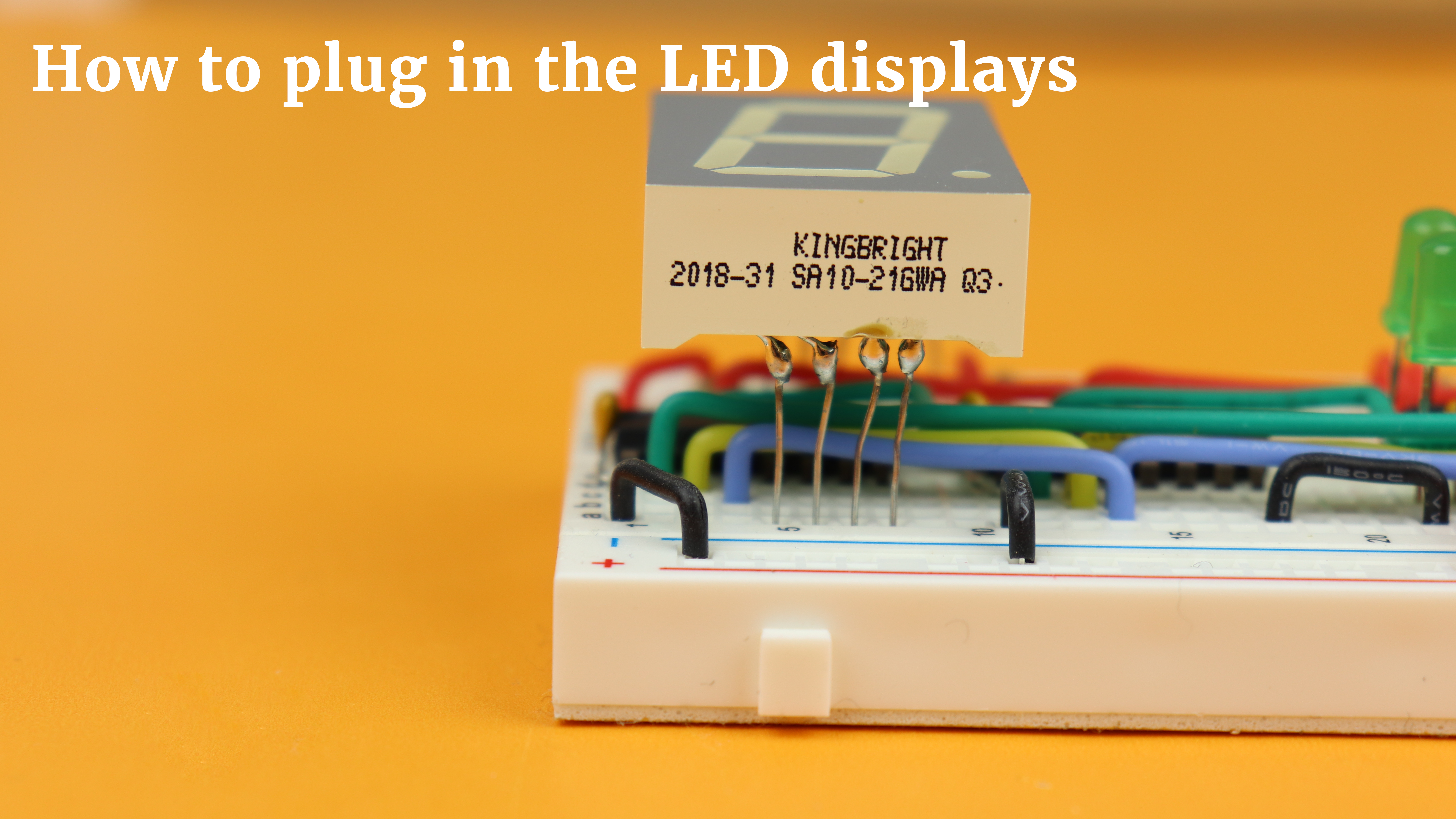
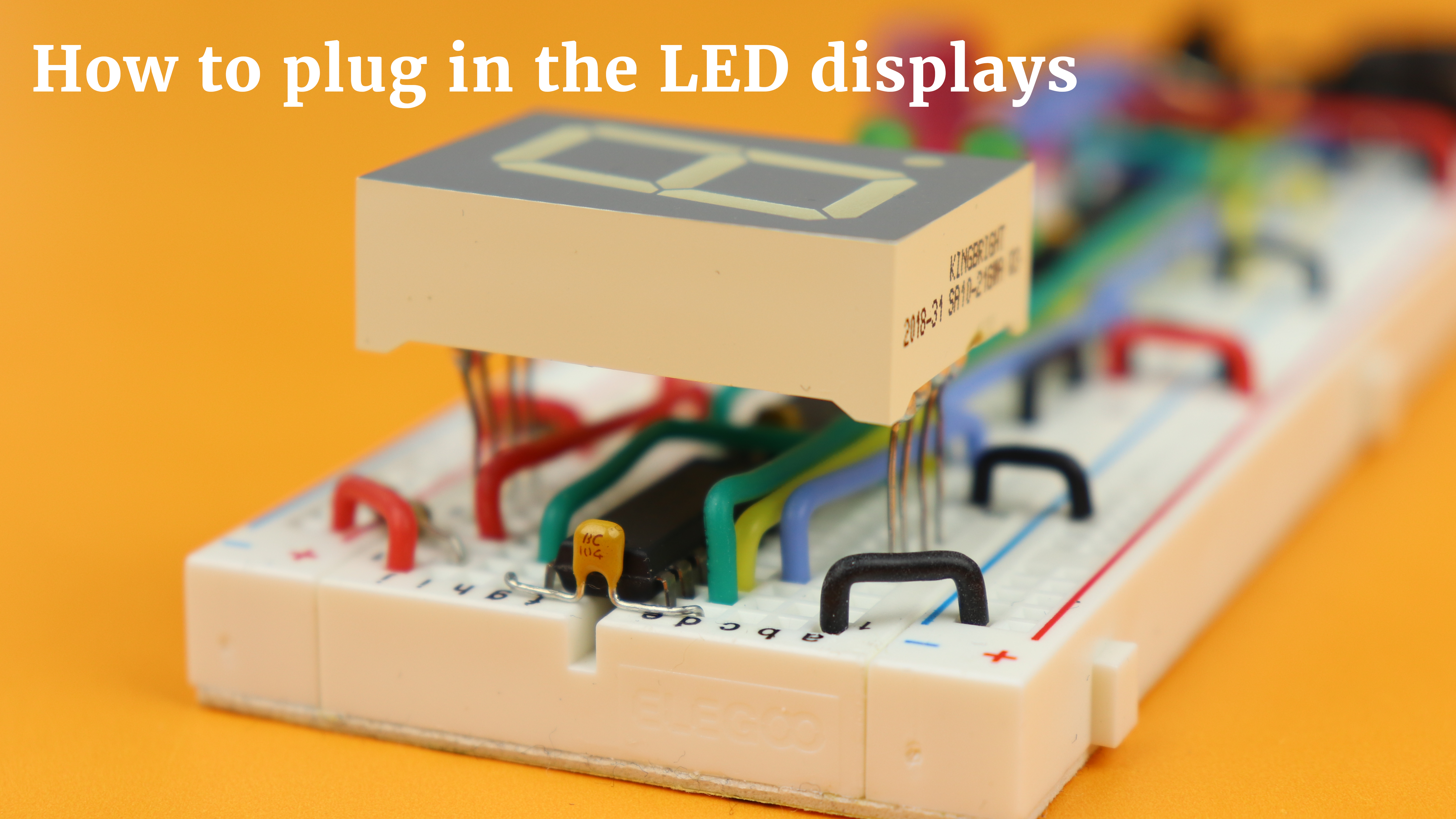
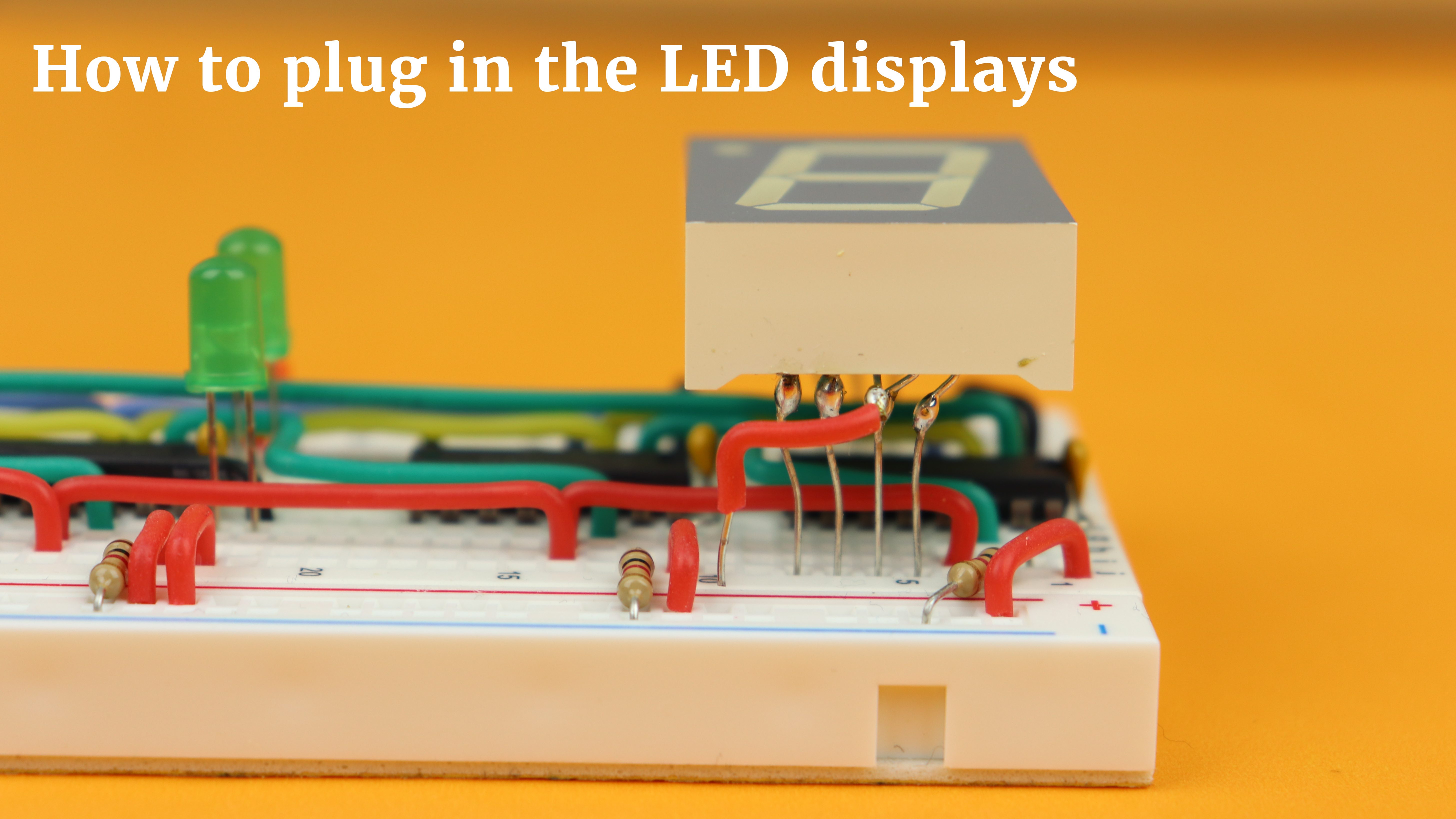
Now you can insert the four 7-segment LED displays. Because we already prepared the displays beforehand, this installation should go super smooth. Remember that the leftmost 7-segment display is the only one that has its decimal point connected. The anode wires can be plugged into the positive power rail at the upper breadboard.
-
-
Step 20
Time to connect power! The best place to connect it is in the middle of each power rail at the top and bottom (around row 31). The positive terminal of the battery compartment goes to the top, and the negative terminal goes to the bottom. And that's it!
If you are having trouble plugging in the LED displays, here are some closeups:
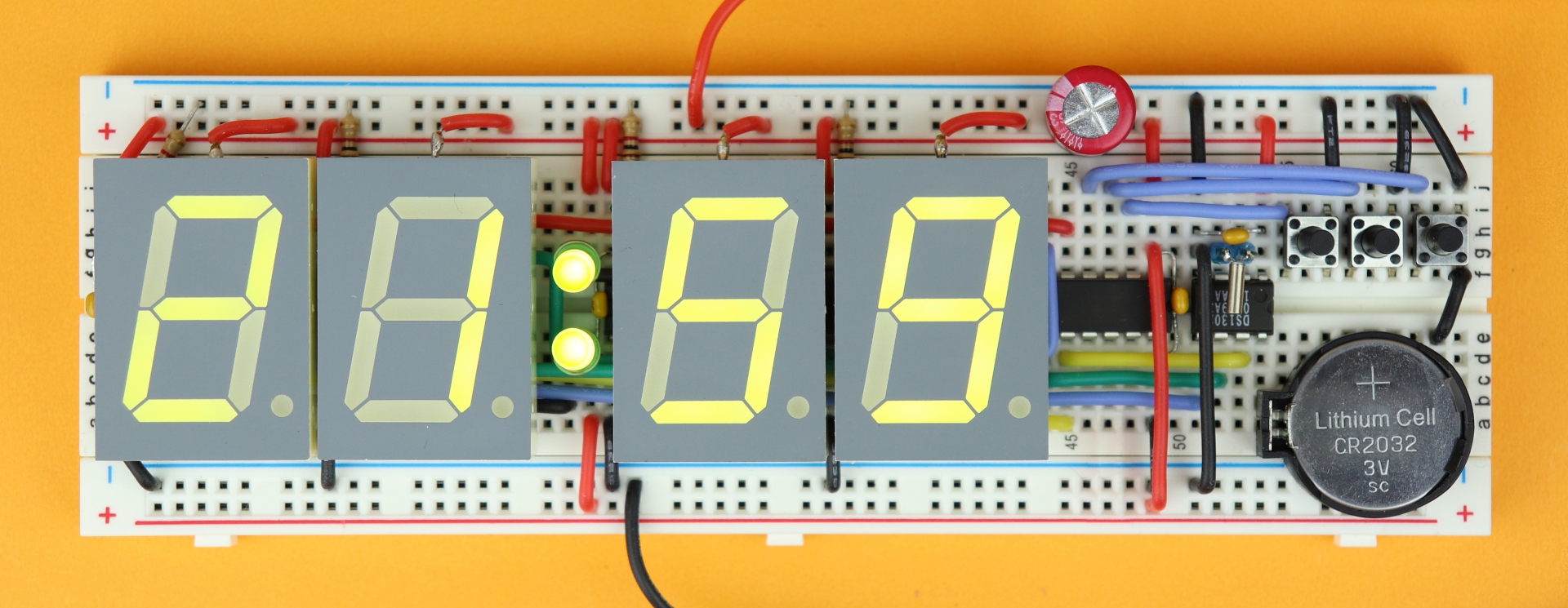
And now you should have a working clock! Press the hour and minute buttons, and the 24-hour button, until the time and format are to your liking. Then, just for fun, go ahead and unplug the 4.5V battery compartment. And then reconnect it again. And you know what? The time is still there, and our battery-buffered clock works!
Some improvements?
As you can imagine, there is always stuff left to improve. In this case it is the power supply situation. As you may have noticed, using the 4.5V battery compartment with bigger LEDs results in a somewhat dim display. That is because larger 7-segment displays have two LEDs in series per segment (except for the decimal point, perhaps) and therefore the forward voltage is quite high. In this case it is close to 4.4V, which barely leaves enough to drive them at any reasonable brightness.
And, as you can imagine, letting this clock run on batteries (even if the LEDs are bright enough) will drain the battery really quickly. So I do not recommend running this clock on batteries, but instead on a 5V power supply (like a USB battery bank maybe).
But keep in mind: this circuit only works with voltages up to 5V, anything more and the PIC16F1455 and the DS1302 will be destroyed.
For that reason I think it would have been a good idea to separate the positive power rails into an LED power rail (at maybe 6-7V) and a logic power rail at 5V exactly. The breadboard was already pretty full with everything, so I figured I'd postpone that for a future project. After all, this project was more about the DS1302 and less about the LEDs.
Another potential issue is the long-term accuracy of this circuit. Since it was built on a breadboard, and breadboards have notoriously large parasitic capacities, it will probably not be very good. The watch crystal for the DS1302 should be one with 6pF load capacity, but if the breadboard itself has some large-ish capacity itself it will bring the crystal slightly out of resonance and the time source won't be exact.
I should also say that there are much more accurate real-time clock modules out there, but for simple hobby applications I think the DS1302 will do just fine.
YouTube video
I covered this entire tutorial in a dedicated YouTube video:
Final thoughts
I had a great time writing and preparing this tutorial because, believe it or not, using a real-time clock had been on my bucket list for years, and I never got around to it.
The clock itself is OK, too, I guess :) But I think in the future I want to use the DS1302 in larger and different clock-type projects. Stay tuned.... :)
As always, thank you very much for reading, and I hope this tutorial was useful to you in some way. If you have any questions, head on over to social media and let me know, and I will do my best to get back to you. Thanks for stopping by, and have a great day!
Appendix: The full source code
Here you can find the full source code. The code (as well as the .hex file) are also available for download in the resources box.
/*
 * File:   main.c
 * Author: boos
 *
 * Created on June 10, 2020, 5:08 PM
 */

// CONFIG1
#pragma config FOSC = INTOSC    // Oscillator Selection Bits (INTOSC oscillator: I/O function on CLKIN pin)
#pragma config WDTE = OFF       // Watchdog Timer Enable (WDT disabled)
#pragma config PWRTE = OFF      // Power-up Timer Enable (PWRT disabled)
#pragma config MCLRE = OFF      // MCLR Pin Function Select (MCLR/VPP pin function is digital input)
#pragma config CP = OFF         // Flash Program Memory Code Protection (Program memory code protection is disabled)
#pragma config BOREN = OFF      // Brown-out Reset Enable (Brown-out Reset disabled)
#pragma config CLKOUTEN = OFF   // Clock Out Enable (CLKOUT function is disabled. I/O or oscillator function on the CLKOUT pin)
#pragma config IESO = OFF       // Internal/External Switchover Mode (Internal/External Switchover Mode is disabled)
#pragma config FCMEN = OFF      // Fail-Safe Clock Monitor Enable (Fail-Safe Clock Monitor is disabled)

// CONFIG2
#pragma config WRT = OFF        // Flash Memory Self-Write Protection (Write protection off)
#pragma config CPUDIV = NOCLKDIV// CPU System Clock Selection Bit (NO CPU system divide)
#pragma config USBLSCLK = 48MHz // USB Low SPeed Clock Selection bit (System clock expects 48 MHz, FS/LS USB CLKENs divide-by is set to 8.)
#pragma config PLLMULT = 3x     // PLL Multipler Selection Bit (3x Output Frequency Selected)
#pragma config PLLEN = ENABLED  // PLL Enable Bit (3x or 4x PLL Enabled)
#pragma config STVREN = ON      // Stack Overflow/Underflow Reset Enable (Stack Overflow or Underflow will cause a Reset)
#pragma config BORV = LO        // Brown-out Reset Voltage Selection (Brown-out Reset Voltage (Vbor), low trip point selected.)
#pragma config LPBOR = OFF      // Low-Power Brown Out Reset (Low-Power BOR is disabled)
#pragma config LVP = OFF        // Low-Voltage Programming Enable (Low-voltage programming disabled)

#include <xc.h>

// how are your segments connected to the TLC5916 driver?
// key:                       a  b  c  d  e  f  g  .
unsigned char seg_to_bit[] = {6, 5, 3, 2, 1, 7, 8, 4};

// useful array to convert 24-hour format into 12-hour mode
// key:                   0, 1, 2, 3, 4, 5, 6, 7, 8, 9, 10, 11, 12, 13, 14, 15, 16, 17, 18, 19, 20, 21, 22, 23
unsigned char get12[] = {12, 1, 2, 3, 4, 5, 6, 7, 8, 9, 10, 11, 12, 1,  2,  3,  4,  5,  6,  7,  8,  9,  10, 11};

// useful array to get the PM bit from 24-hour data
// key:                   0, 1, 2, 3, 4, 5, 6, 7, 8, 9, 10, 11, 12, 13, 14, 15, 16, 17, 18, 19, 20, 21, 22, 23
unsigned char getPM[] = { 0, 0, 0, 0, 0, 0, 0, 0, 0, 0, 0,  0,  1,  1,  1,  1,  1,  1,  1,  1,  1,  1,  1,  1};

// real-time clock functions
void sendRTC (unsigned char value);
unsigned char getRTC (void);

// LED display functions
void sendValue (unsigned char value);
unsigned char convertNumberToPattern (unsigned char number);

// define locations of jumper and pushbuttons
#define SW_HRS !RA5
#define SW_MIN !RA4
#define SW_24H !RA3

// define locations of data connections
#define SDI RC3
#define LE RC4
#define CLK RC0
#define nOE RC5
#define RTC_IO RC1
#define RTC_CE  RC2

// variables
int SW_HRS_BUFFER, SW_MIN_BUFFER, SW_24H_BUFFER, BLINK_BUFFER;
unsigned char hours=0, hours10=0, hours1=0, minutes10=0, minutes1=0, seconds10=0, seconds1=0, seconds1old=0;
unsigned char tmp=0, dots=0, mode24=1;

// main function
void main (void) {

    // set internal oscillator to 4MHz
    IRCF0 = 1;
    IRCF1 = 0;
    IRCF2 = 1;
    IRCF3 = 1;

    // weak pull-up for buttons
    TRISA4 = 1;
    TRISA5 = 1;
    WPUA3 = 1;
    WPUA4 = 1;
    WPUA5 = 1;
    nWPUEN = 0;

    // set input/output tri state registers
    TRISC0 = 0;
    TRISC1 = 0;
    TRISC2 = 0;
    TRISC3 = 0;
    TRISC4 = 0;
    TRISC5 = 0;

    // turn off analog features
    ANSC0 = 0;
    ANSC1 = 0;
    ANSC2 = 0;
    ANSC3 = 0;
    ANSA4 = 0;

    // TIMER0 settings

	// internal clock, no prescaler, interrupt on overflow
	TMR0CS = 0;
	PSA = 1;
	TMR0IE = 1;

	// enable global interrupts
	GIE = 1;


    // main loop
    while (1) {


        // ********************************************************************
        // PART 1: READ DATA FROM REAL-TIME CLOCK

        // retrieve seconds
        RTC_CE = 1;
        sendRTC(0x81);
        tmp = getRTC();
        RTC_CE = 0;
        seconds10 = (tmp & 0b01110000) >> 4;
        seconds1  = tmp & 0b00001111;

        // retrieve minutes
        RTC_CE = 1;
        sendRTC(0x83);
        tmp = getRTC();
        RTC_CE = 0;
        minutes10 = (tmp & 0b01110000) >> 4;
        minutes1  = tmp & 0b00001111;

        // retrieve hours
        RTC_CE = 1;
        sendRTC(0x85);
        tmp = getRTC();
        RTC_CE = 0;

        // Is the mode set to AM/PM?
        if (tmp >> 7) {

            // Set mode to 24-hour mode.
            // (Conversion to 12-hour mode, if required, is done by us in the code.)
            RTC_CE = 1;
            sendRTC(0x84);
            sendRTC(1<<7);
            RTC_CE = 0;

            // Re-read the hours again, this time in the proper 24-hour format.
            RTC_CE = 1;
            sendRTC(0x85);
            tmp = getRTC();
            RTC_CE = 0;

        }

        // extract tens and ones for the hours
        hours10 = (tmp & 0b00110000) >> 4;
        hours1  = tmp & 0b00001111;

        // generate the 24-hour hours value
        hours = 10*hours10 + hours1;

        // find current mode
        RTC_CE = 1;
        sendRTC(0xc1);
        mode24 = getRTC();
        RTC_CE = 0;


        // ********************************************************************
        // PART 2: DISPLAY DATA ON LEDs

        // send seconds (and include the blinking dots)
        sendValue(convertNumberToPattern(seconds1));
        sendValue(convertNumberToPattern(seconds10) | (dots << 0));

        // send minutes (and include the blinking dot)
        sendValue(convertNumberToPattern(minutes1)  | (dots << 0));
        sendValue(convertNumberToPattern(minutes10) | (dots << 0));

        // 24-hour mode
        if (mode24) {

            // send hours (and include the blinking dot)
            sendValue(convertNumberToPattern(hours1) | (dots << 0));
            sendValue(convertNumberToPattern(hours10));

        // 12-hour mode
        } else {

            // send hours (and include the blinking dot as well as the PM indicator)
            tmp = get12[hours] % 10;
            sendValue(convertNumberToPattern(tmp) | (dots << 0));
            tmp = get12[hours] / 10;
            sendValue(convertNumberToPattern(tmp) | getPM[hours]);

        }

        // update all data in the registers
        LE = 1;
        LE = 0;


        // ********************************************************************
        // PART 3: REACT TO USER INPUT,
        // AND UPDATE REAL-TIME CLOCK DATA IF NECESSARY

        // has the HOUR button been pressed?
        if ((SW_HRS) && (SW_HRS_BUFFER == 0)) {

            // increase hours
            hours++;
            if (hours > 23) {
                hours = 0;
            }

            // calculate new ones and tens
            hours1 = hours % 10;
            hours10 = hours / 10;

            // update hours in real-time clock
            RTC_CE = 1;
            sendRTC(0x84);
            sendRTC( (hours10 << 4) | hours1 );
            RTC_CE = 0;

            // reset seconds
            RTC_CE = 1;
            sendRTC(0x80);
            sendRTC(0);
            RTC_CE = 0;

            // reset debounce variable
            SW_HRS_BUFFER = 50;

        }

        // has the MINUTE button been pressed?
        if ((SW_MIN) && (SW_MIN_BUFFER == 0)) {

             // increase minutes
            minutes1++;
            if (minutes1 > 9) {
                minutes1 = 0;
                minutes10 += 1;
                if (minutes10 > 5) {
                    minutes10 = 0;
                }
            }

            // update minutes in RTC
            RTC_CE = 1;
            sendRTC(0x82);
            sendRTC( (minutes10 << 4) | minutes1 );
            RTC_CE = 0;

            // reset seconds
            RTC_CE = 1;
            sendRTC(0x80);
            sendRTC(0);
            RTC_CE = 0;

            // reset debounce variable
            SW_MIN_BUFFER = 50;

        }

        // has the 24-HOUR button been pressed?
        if ((SW_24H) && (SW_24H_BUFFER == 0)) {

            // increase brightness mode
            mode24 = 1 - mode24;

            // store new mode
            RTC_CE = 1;
            sendRTC(0xc0);
            sendRTC(mode24);
            RTC_CE = 0;

            // reset debounce variable
            SW_24H_BUFFER = 100;

        }

    }

    return;

}

// The interrupt service routine handles the blink animation of the dots
// as well as the debouncing of the three pushbuttons.
void __interrupt () isr (void) {

    // this is called abound 3900 times per second
	if (TMR0IF) {

        // blink animation
        BLINK_BUFFER += 1;
        if (seconds1 != seconds1old) {
            seconds1old = seconds1;
            BLINK_BUFFER = 0;
        }
        if (BLINK_BUFFER < 1950) {
            dots = 1;
        } else {
            dots = 0;
        }

        // debounce the buttons
        if ((!SW_HRS) && (SW_HRS_BUFFER > 0)) { SW_HRS_BUFFER -= 1; }
        if ((!SW_MIN) && (SW_MIN_BUFFER > 0)) { SW_MIN_BUFFER -= 1; }
        if ((!SW_24H) && (SW_24H_BUFFER > 0)) { SW_24H_BUFFER -= 1; }

		// reset interrupt flag
		TMR0IF = 0;

	}

}

// This function sends the byte "value" to the RTC.
void sendRTC (unsigned char value) {

    // set data port as output
    TRISC1 = 0;

    // auxiliary index variable
	char n = 0;

    // loop over all eight bits
	for (n = 0; n < 8; n++) {
        RTC_IO = (value >> n) & 1;
        CLK = 1;
        CLK = 0;
    }

}

// This function receives a byte from the RTC
// and returns it to the program.
unsigned char getRTC (void) {

    // set data port as input
    TRISC1 = 1;

    // dummy variables
    unsigned char value = 0;
    char n = 0;

    // collect all eight bits
    for (n = 0; n < 8; n++) {
        value |= (RTC_IO << n);
        CLK = 1;
        CLK = 0;
    }
    return value;

}

// This function sends an eight-bit value
// to the TLC5916 driver ICs.
void sendValue (unsigned char seg_pattern) {

    // store decoded segment pattern here
    unsigned char bit_pattern = 0;

    // decode segment pattern into bit pattern
    for (int n = 0; n < 8; n++) {
        if ((seg_pattern >> (7-n)) & 1) {
            bit_pattern |= 1 << (seg_to_bit[n] - 1);
        }
    }

    // send bit pattern bit by bit,
    // starting with the most significant bit
	for (int n = 7; n >= 0; n--) {

        SDI = (bit_pattern >> n) & 1;
        CLK = 1;
		CLK = 0;

	}

    // set data pin back to zero
    SDI = 0;

}

// This function converts a number into the 7-segment pattern.
unsigned char convertNumberToPattern (unsigned char number) {

    // what is the number?
    switch (number) {

        // numbers       abcdefg.
        case 0: return 0b11111100;
        case 1: return 0b01100000;
        case 2: return 0b11011010;
        case 3: return 0b11110010;
        case 4: return 0b01100110;
        case 5: return 0b10110110;
        case 6: return 0b10111110;
        case 7: return 0b11100000;
        case 8: return 0b11111110;
        case 9: return 0b11110110;

        // default symbol is an empty space
        default: return 0b00000000;

    }

}


