How to configure your PIC microcontroller
August 17, 2019 • tutorial
In every single PIC microcontroller project we do it: set the configuration bits. But what does that accomplish? In this tutorial we will go through the basic options for these “configuration bits” and we will focus on the PIC16F627A microcontroller so that we have a concrete example.
Other microcontrollers have almost the same or rather different configuration bits, it depends. Still, this tutorial will hopefully give you some pointers what configuration bits are all about.
Before getting into the nitty gritty of microcontrollers, let's forget about microcontrollers for a second and let us talk about computers instead. We all know: sometimes, after we install a program, we need to restart the computer. And why? Most of the times, the installation of new software makes deep changes to the system. We can think of the microcontroller's configuration bits the same way: they control very fundamental aspects of how the controller works.
There are a few important details to configuration bits:
- Configuration bits can only be set at the beginning of the program and cannot be changed dynamically during the operation of the controller.
- Configuration bits offer the deepest level of control we have over the microcontroller.
- We can think of configuration bits as software wires that are welded into place permanently. Maybe this analogy sounds strange, but for Atmel microcontrollers of the AVR family (which, as of 2016, has been acquired by MicroChip who makes the PIC microcontrollers) the configuration bits are called fuses. I think this is a very fitting name.
Okay, so the configuration bits are very fundamental. Got it. Now what?
To be concrete, let us focus on the PIC16F627A microcontroller for the rest of this tutorial. This may sound a bit restrictive, but in fact many of the topics we will cover apply to almost any other PIC controller as well.
Using MicroChip's MPLAB IDE to find configuration bits for any microcontroller
You might think that you need to study the datasheet of a controller to figure out how to set the configuration bits. But that's not true when you decide to use MPLAB IDE, MicroChip's integrated development environment for PIC microcontrollers. As we have learned in our first microontroller program, there is a simple way to find the configuration bits.
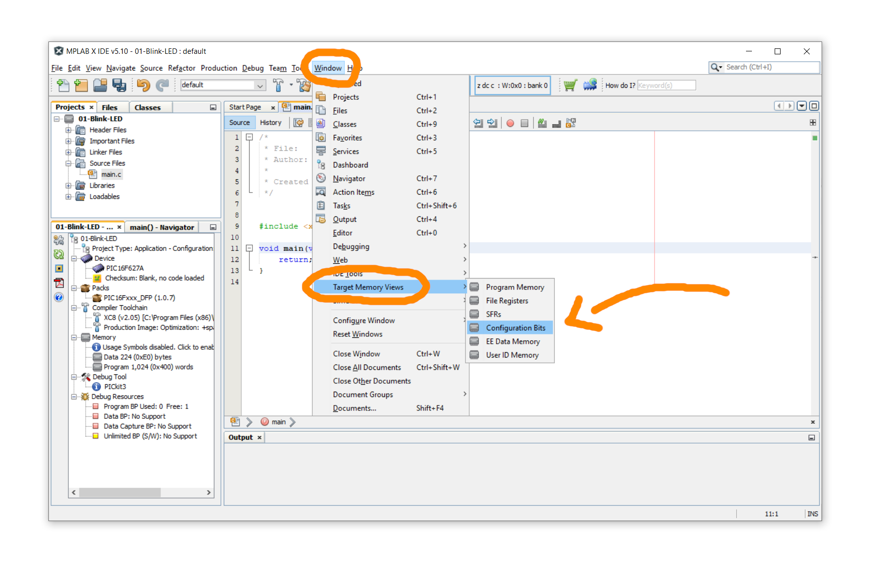
In your MPLAB project, click on Window → Target Memory Views → Configuration Bits:
Then, a menu appears where you can select all options manually in dropdown lists (we will explain what all these options mean in just a second). After selecting all options, you can click on Generate Source Code to Output which gives you a piece of text you can copy and paste into your source code.
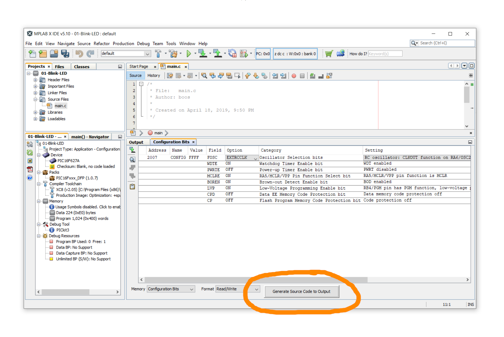
After selecting some options, the source code may look like the one listed below (In fact, the above screenshot does NOT correspond to the source code below, a few values are different. Can you spot the differences?):
// CONFIG
#pragma config FOSC = XT        // Oscillator Selection bits (XT oscillator: Crystal/resonator on RA6/OSC2/CLKOUT and RA7/OSC1/CLKIN)
#pragma config WDTE = ON        // Watchdog Timer Enable bit (WDT enabled)
#pragma config PWRTE = OFF      // Power-up Timer Enable bit (PWRT disabled)
#pragma config MCLRE = ON       // RA5/MCLR/VPP Pin Function Select bit (RA5/MCLR/VPP pin function is MCLR)
#pragma config BOREN = ON       // Brown-out Detect Enable bit (BOD enabled)
#pragma config LVP = OFF        // Low-Voltage Programming Enable bit (RB4/PGM pin has digital I/O function, HV on MCLR must be used for programming)
#pragma config CPD = OFF        // Data EE Memory Code Protection bit (Data memory code protection off)
#pragma config CP = OFF         // Flash Program Memory Code Protection bit (Code protection off)
Now what does that all mean? Let us first make an important distinction:
- In our example, there are eight options (FOSC, WDTE, PWRTE, MCLRE, BOREN, LVP, CPD, CP).
- Each of these options can take values. These values can be ON or OFF, but they can also be more complicated, like HS or XT or INTOSCIO.
Don't worry, it will all make sense in a bit :) Get it...? It's funny because we are talking about configuration bits. OK, moving on...
FOSC: oscillator selection
This is probably the most important configuration. It tells the controller where to take the clock signal from (read more about what makes a microcontroller tick). We have the choice between an internal clock, an external RC circuit, or an external crystal.
- EXTRCCLK: RC oscillator: CLKOUT function on RA6, resistor and capacitor on RA7.
- EXTRCIO: RC oscillator: I/O function on RA6, resistor and capacitor on RA7.
- INTOSCCLK: INTOSC oscillator: CLKOUT function on RA6, I/O function on RA7.
- INTOSCIO: I/O function on RA6 and RA7.
- EC: I/O function on RA6, CLKIN on RA7.
- HS: HS oscillator: High-speed crystal/resonator on RA6 and RA7.
- XT: XT oscillator: crystal/resonator on RA6 and RA7.
- LP: LP oscillator: low-power crystal on RA6 and RA7.
In our projects, we mostly use INTOSCIO when we need an internal oscillator and want to save some external components. Alternatively, if we connect a regular crystal we will go with the option XT. If it is a fast crystal (say, above 12 MHz or so), it is better to select the high-speed option HS. So far, personally, I have not used the RC option.
WDTE: Watchdog timer

The watchdog timer is a whole topic on its own. At the time of writing this article, none of our projects use it, so I won't go into too much detail. We can either turn it on or off:
- ON: watchdog timer is on.
- OFF: watchdog timer is off.
Roughly speaking, a watchdog timer helps a microcontroller to reset itself when something goes wrong. It is clear that the watchdog timer has to be a separate entity from the controller. The controller, if the program is running smoothly, checks in with the watchdog timer on a periodic basis, and let's it know that everything is OK. If the watchdog timer doesn't receive such confirmation, it will reset the controller.
This feature is important in circuits that need to be extremely reliable (space probes, medical equipment, and so on). It may not surprise you that for our projects it is not really required ;-) This is why we usually turn the watchdog timer OFF.
PWRTE: Power-up timer

Some power supplies take a certain time to turn on safely, and during that time they may not behave in a stable fashion. This is when you can use a power-up timer: it starts the PIC controller with a small delay that allows the powre supply to become stable.
- ON: power-up timer is on.
- OFF: power-up timer is off.
In our projects we try to use decent and clean power supplies that don't tax our poor controllers more than necessary, which is why we usually disable this option. However, when your controller works in an electrically noisy environment it might be worth looking into :)
MCLRE: Master clear pin function

The master clear pin is used to flash a microcontroller. But sometimes it is nice to have an extra I/O port, and this option turns the MCLR pin into a regular I/O port.
- ON: RA5 pin function is MCLR.
- OFF: RA5 pin function is I/O, MCLR internally tied to VDD.
This option is very useful if you need an extra I/O pin, but in that case it is no longer possible to reset the PIC microcontroller externally, unless you want to switch off the power supply. Turning the MCLR pin into an I/O port does not affect the flashing of the controller in any way.
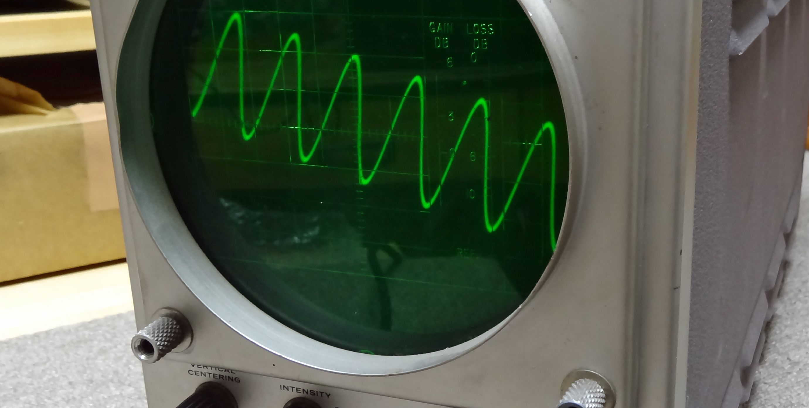
BOREN: Brown-out detect

The picture above shows a blackout, sure. A brown-out is similar, but not as severer: the power fluctuates, but does not go off entirely. For a microcontroller it is disastrous regardless: if the voltage reduces from, say, +5V to +3V instantaneously, all the logic levels shift, and the controller might react in an unpredictable manner.
This is where the brown-out detection come in: if such a fluctuation is detected, the controller gets reset.
- ON: brown-out detection is on.
- OFF: brown-out detection is off.
Much like the power-up timer, this option is useful for noisy power lines. In our projects it is not really necessary, so we turn it off,
LVP: low-voltage programming

Programming devices that are used to flash a microcontroller, such as the PICkit3, use a voltage higher than the PIC's operating voltage (typically around +12V) to initiate the programming process. If, for some reason, you don't want to do that (say, if only +5V is available), a second pin is required: the so-called PGM pin (which for the PIC16F627A is pin RB4).
- ON: low-voltage programming is on, and pin RB4 has PGM function.
- OFF: low-voltage programming is off, and pin RB4 has I/O function.
Low-voltage programming mode is advantageous because it only uses +5V. However, it needs one more pin (the PGM pin). Also, the PGM pin might be used for a secondary function in a certain project, and this external circuitry can interfere with the programming mode and lead to instabilities.
If you use a programmer like the PICkit3, I recommend to disable the LVP feature because it is really not necessary. Please let me know if you know of a good situation when LVP is absolutely essential, I would love to hear about it :)
CPD: EEPROM memory code protection
Many microcontrollers offer an EEPROM, that is, electrically erasable and programmable read-only memory. This memory might contain sensitive information (software activation keys, sensible measurement data) that needs to be protected from external access (say, somebody pokes the controller with a probe). This is what this option is for.
- ON: data memory code protection is on.
- OFF: data memory code protection is off.
Needless to say, so far, at the writing of this article, we have not even used the EEPROM module in any microcontroller. Since our projects don't contain any sensible data, I probably won't bother to turn this option on. If turned on, however, it makes sure that the EEPROM is only accessed from within the PIC's program and not externally.
CP: code protection
Sometimes the PIC microcontroller's source code contains a very clever functionality, or algorithm, that needs to be protected (either for security or intellectual property/license reasons). Protected from what? It is possible to extract the .hex code that is stored on a microcontroller!
- ON: code protection is on.
- OFF: code protection is off.
We don't use this option in any of our projects.
Final thoughts
And there you have it! I hope I could convince you that configuration bits are actually quite easy to understand. If you use MPLAB IDE, which is a free software, make sure to check out the integrated configuration bit menu explained above.
It is true that some controllers offer slightly different configuration bits, but if you understand that the configuration bits of the PIC16F627A do, then you will be well-equipped to tackle more advanced options of other controllers :)
If there is something in this tutorial that does not make any sense to you, please let me know on social media, and I will do my best to explain it better :) Thanks for reading!


