CD4026 decimal counter tutorial
November 17, 2019 • tutorial
The CD4026 is an integrated circuit (IC) that works as a counter from 0-9 with an integrated decoder for a 7-segment display. I think it is an ideal beginner circuit for anybody who wants to learn electronics. In this tutorial we will go through the very basics of this IC and learn, step by step, how to connect it to pushbuttons, a 7-segment display, and a battery, to build our own counter!
If you are interested in building this counter yourself, there is a detailed list of all required components, including links to where to purchase everything. You don't need a lot of tools for this project either, and it is completely solderless because it uses a breadboard.
Okay, let's get started!
What do you need?
Here is a picture of all the components that are needed for the CD4026 counter:
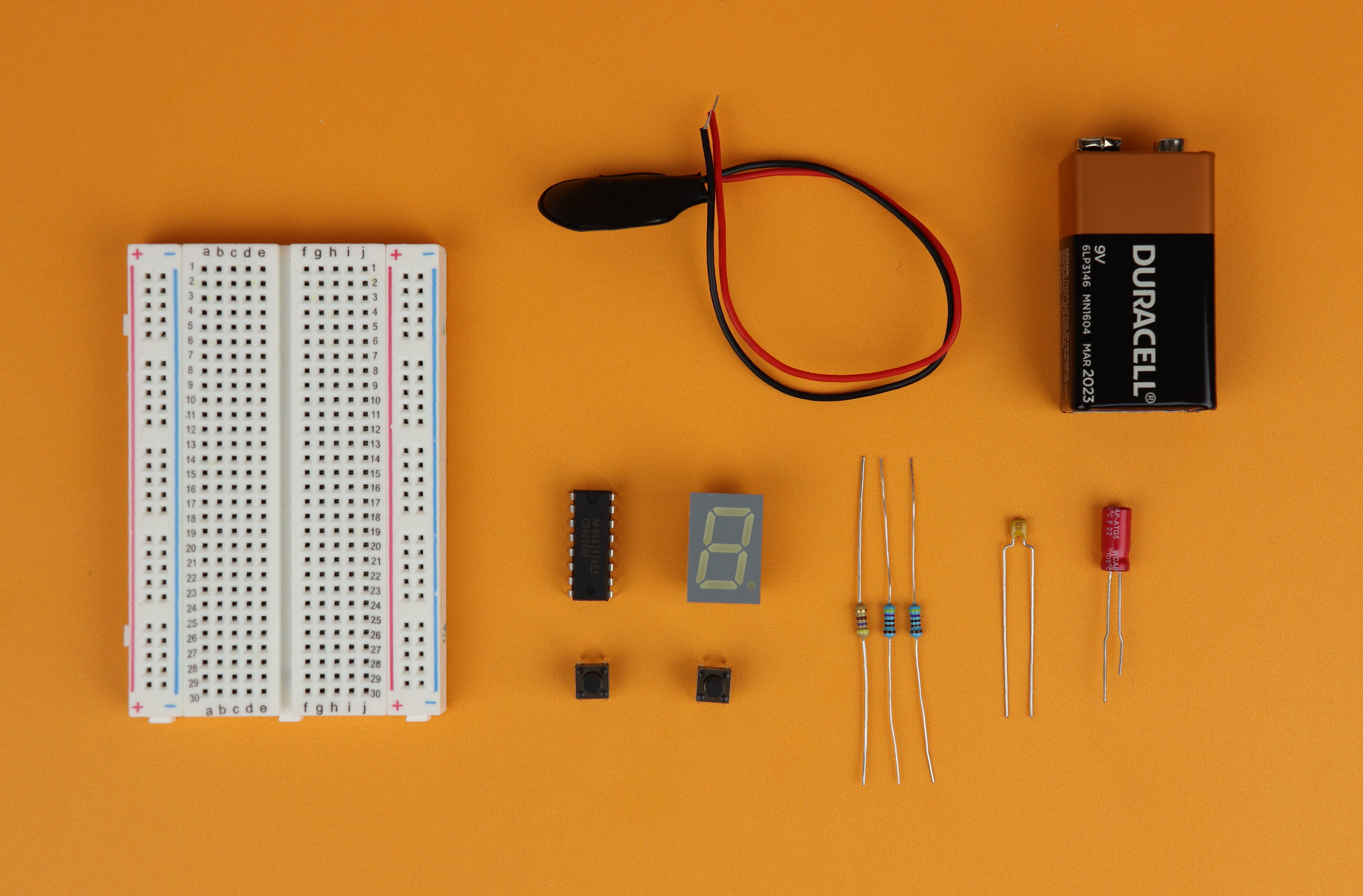
On the left you have the 400-pin breadboard, and at the top you can see a standard 9V battery with a battery clip we will use as a power supply. Unlike microcontrollers, CMOS ICs like the CD4026 work well with a voltage from 3-18V DC. The other components are rather minimal: there is the CD4026 itself, a common-cathode 7-segment display (more on that below), two pushbuttons, three resistors, and two capacitors.
We also need some wire, and you can use either readily made jumper wires (which gets a bit messy because the wires are usually too long) or you can make your own from single-stranded AWG 24/0.6mm wire. Check out the components box for where to buy the components.
The amount of tools required is also minimal, but I recommend a set of side cutters and pliers. But how do we connect it all together?
The schematic
This is the schematic for the CD4026 counter:
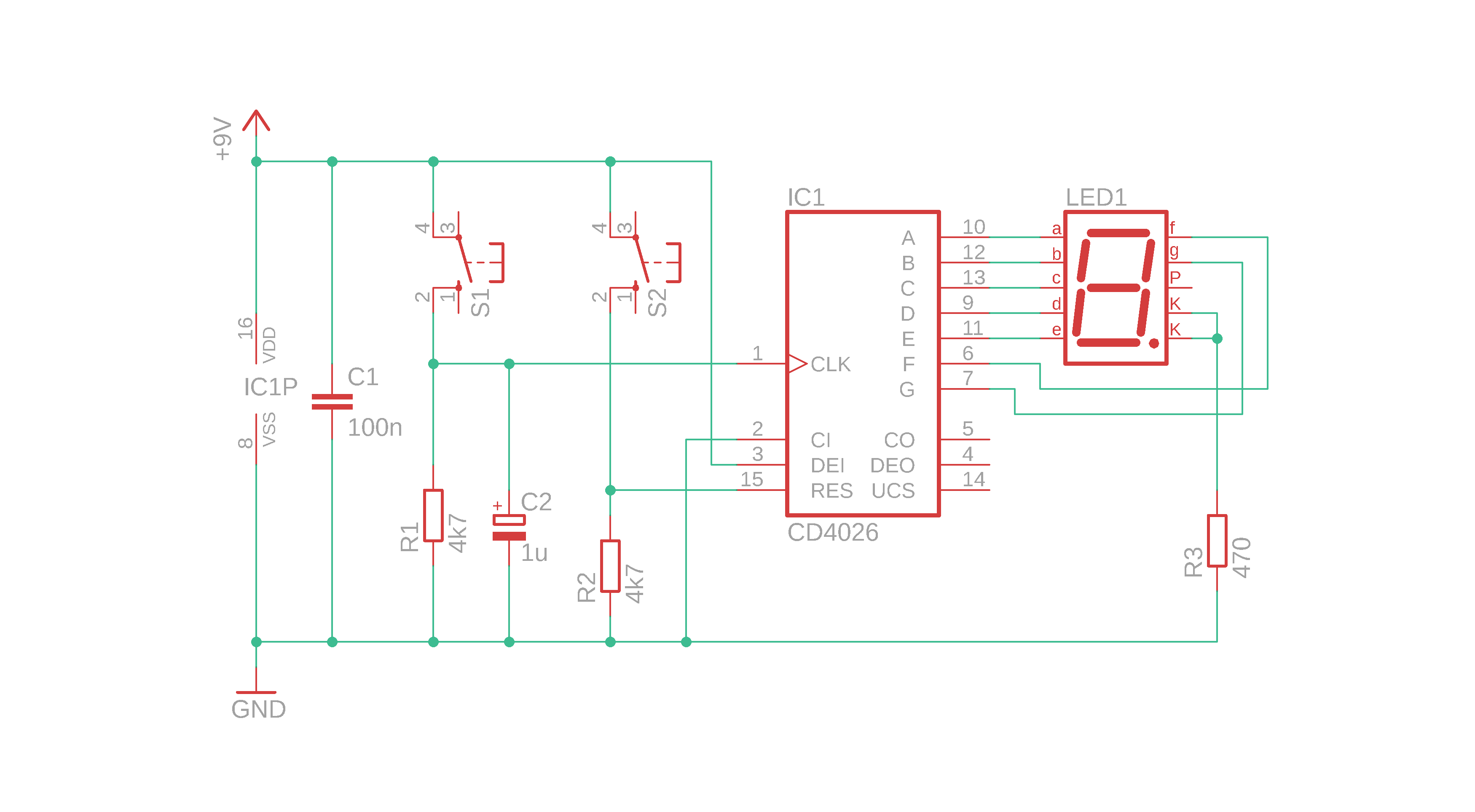
You can find a more detailed explanation for the functionalities of the CD4026 in the CMOS tutorial. If you are new to reading schematics, consider checking out our tutorial on how to read schematics as well :) Okay, let's go through the schematic, step by step:
- +9V is the positive power rail where we connect the positive terminal of the battery, and GND is the ground terminal where the negative terminal of the 9V battery is connected.
- C1 is a filter capacitor that smooths the operating voltage. It is not really needed for battery operation (since battery voltage is super clean), but if you ever decide to connect this circuit instead to a 9V DC power adapter you will be all set. So better include it :)
- IC1P on the very left is not a separate component, but it stands for the power connections for the CD4026. This is a bit confusing, but for CMOS ICs the power connections are usually displayed as separate symbols (see also our article here).
- IC1 is the heart of the counter. A positive pulse on the CLK (clock) input increases the counter value, and a positive pulse on the RES (reset) resets the counter. We have to connect CI (clock inhibit) to GND because otherwise the CD4026 will ignore clock pulses. DEI (display enable in) has to be tied to +9V, because otherwise the connected display (see below) will remain dark. The pins A-G are the outputs for the 7-segment display.
- S1 acts as the increment button. Whenever you push it, the counter counts up by 1. The resistor R1 serves as a pulldown resistor: this way, the CLK input is on a well-defined logic level (LOW) whenever the button is not pushed. The capacitor C2 is a simple way to debounce the pushbutton S1. If you omit C2, pressing S1 will likely increase the counter not just by 1 but by much more.
- S2 is the reset button, and R2 is its pulldown resistor. We do not really need a debounce capacitor on the reset line because it does not matter if the counter resets once or twice in rapid succession, so I omitted it.
- LED1 is our 7-segment display with a common cathode. The resistor R3 limits the current that flows through the LEDs. It is not a very clean solution: we should add a separate resistor for each segment. This way we save on the number of total components (because we need only one current-limiting resistor as opposed to seven), but the trade off is that the display will have slightly uneven brightness: the digit 1 will be brighter than the number 8, because in case of the number 1 only two segments share the current, whereas for number 8 all seven segments share the current. if you build it yourself, feel free to add separate resistors :)
And that's it! Now that we understand the schematic we can go ahead and build it!
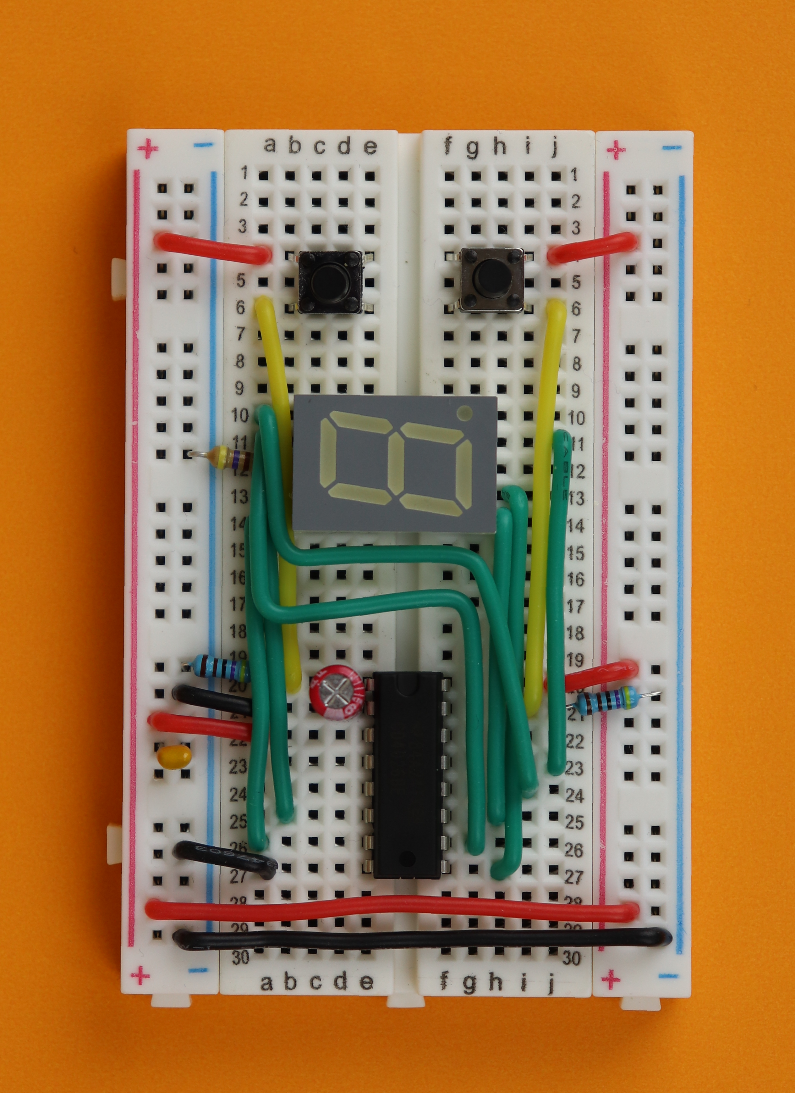
Building the circuit
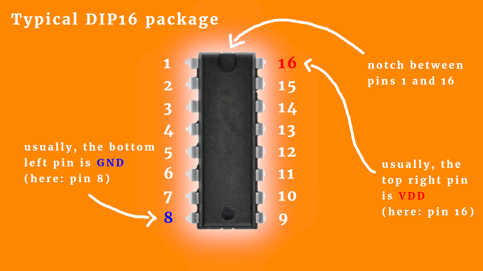
Before we begin I want to talk a bit about the CD4026 IC as well as the 7-segment LED display. They come in a special housing, and these housings have pins, and these pins have numbers. And, quite frankly, it is always a good idea to think about where to connect what before actually doing it :)
The CD4026 comes in a dual-inline package with 16 overall pins, which is why its package is also called DIP16. Here you can see the pin numbering convention:
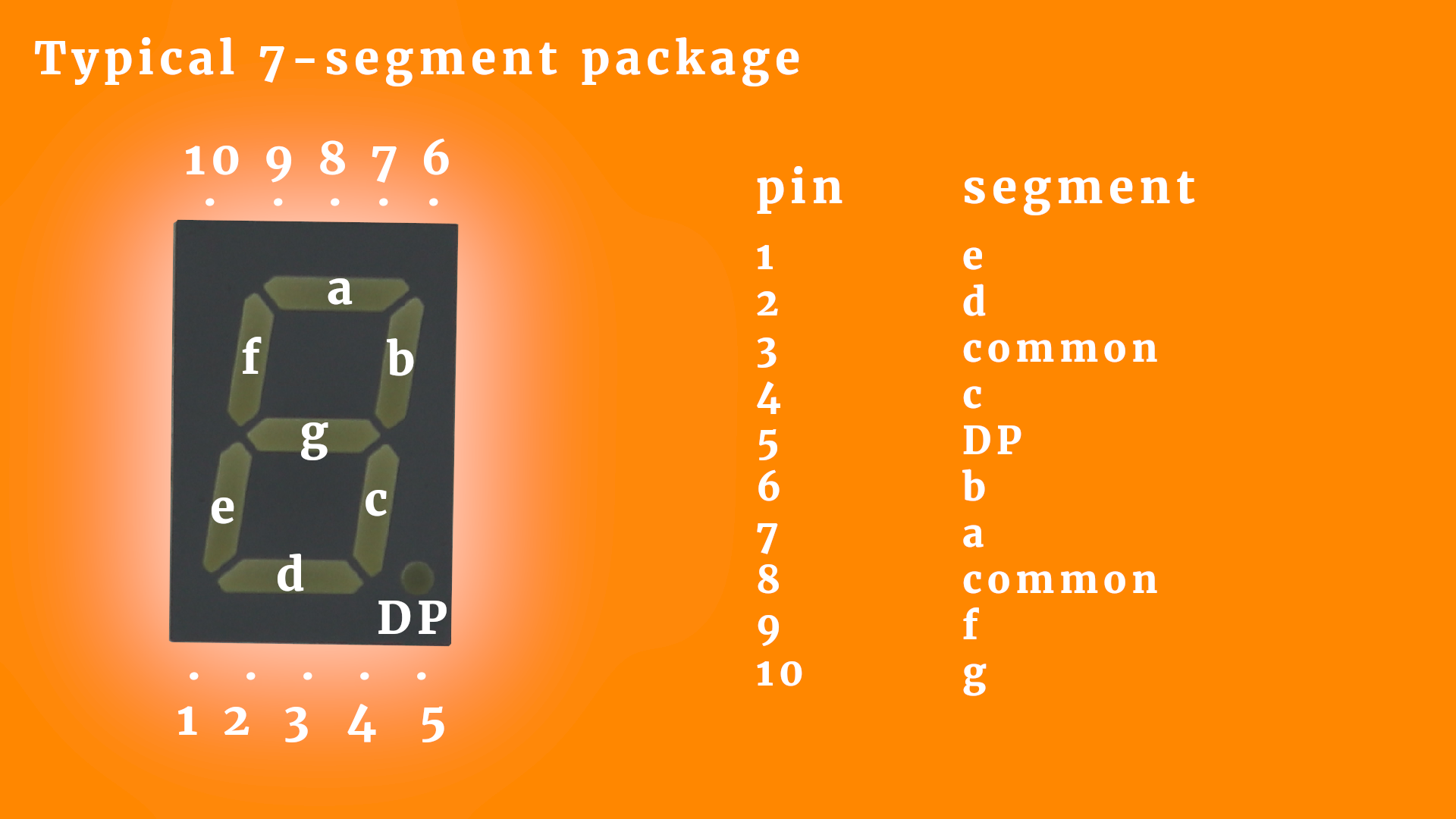
7-segment displays consist of seven LEDs (or eight, if they have a decimal point). They have one common pin, which can either be the cathode or the anode:

The seven segments are aligned in such a way that they can display all numbers from 0-9 as well as some letters. This is the typical pinout of such a display:
Alright! Now that this is out of the way we can start building the circuit!
-

-
Step 1
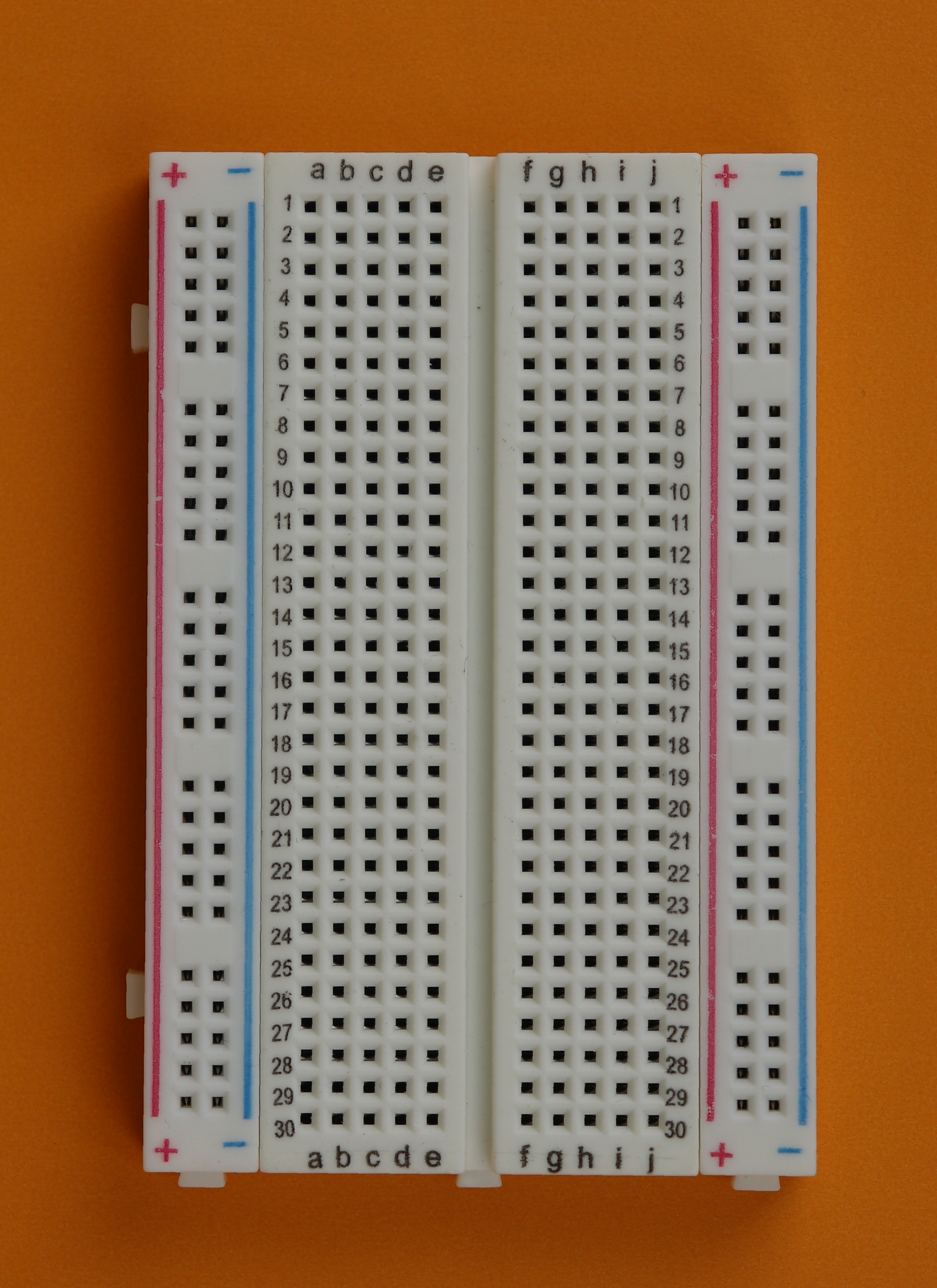
Place the 400-pin breadboard in front of you :)
-
-
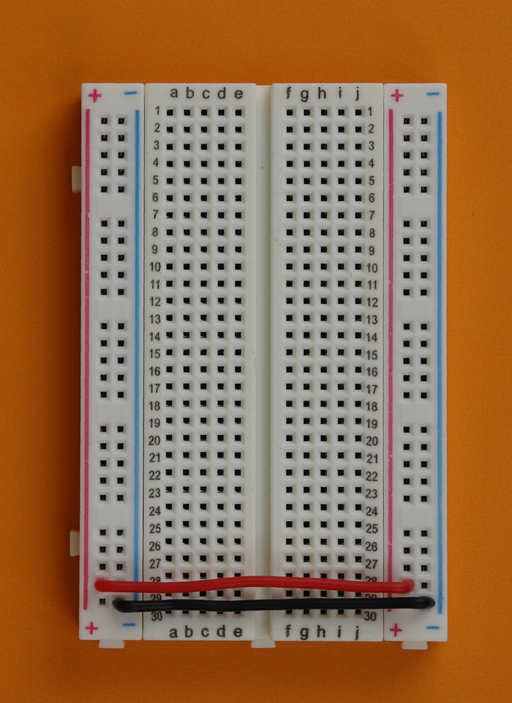
Step 2
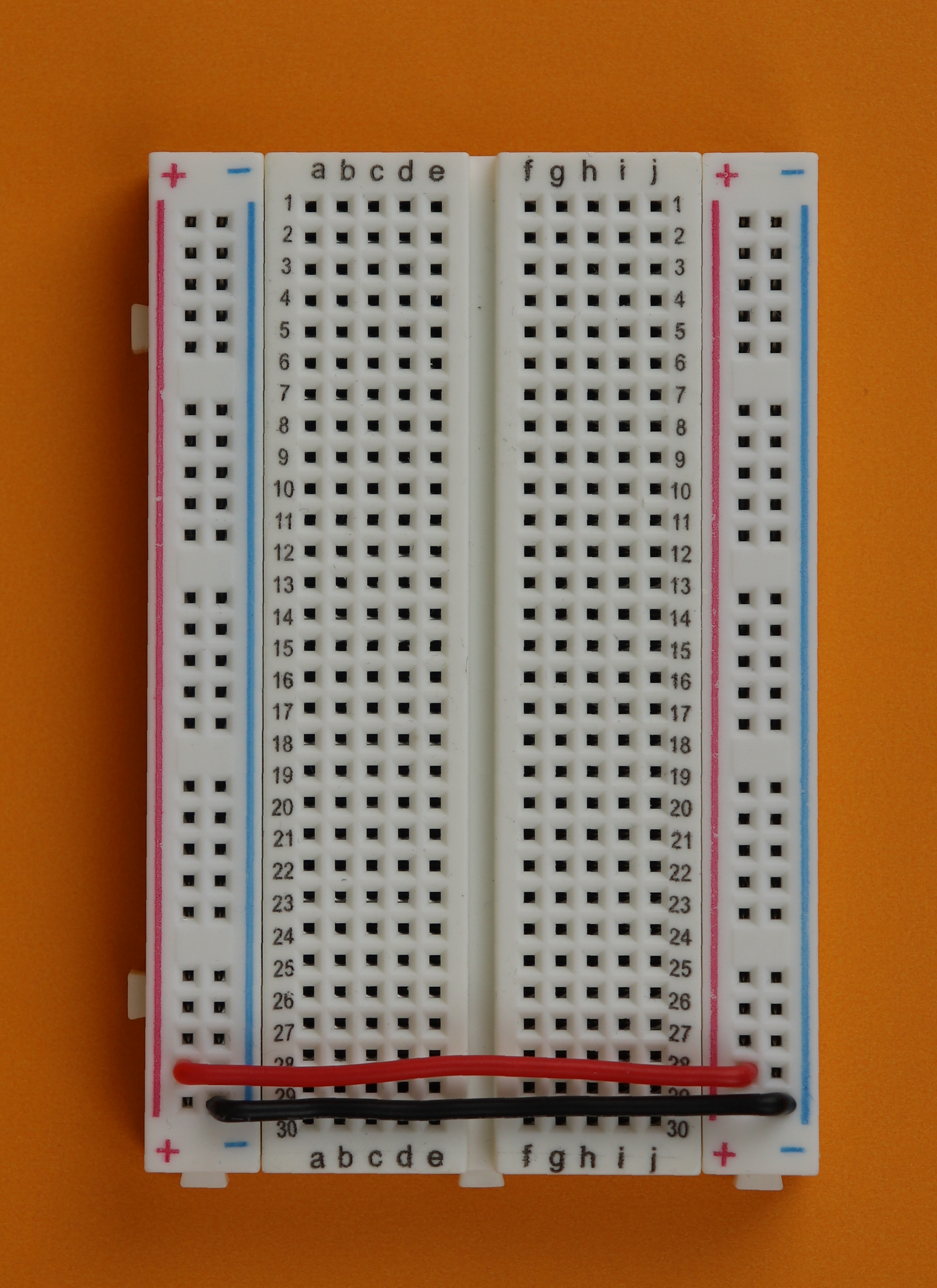
First, connect the two power rails on both sides. This will be very convenient later.
-
-
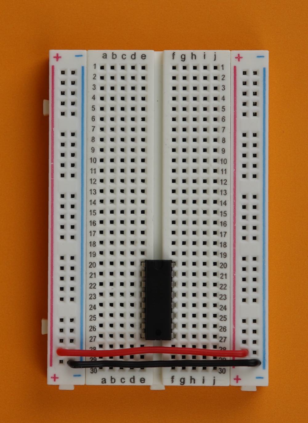
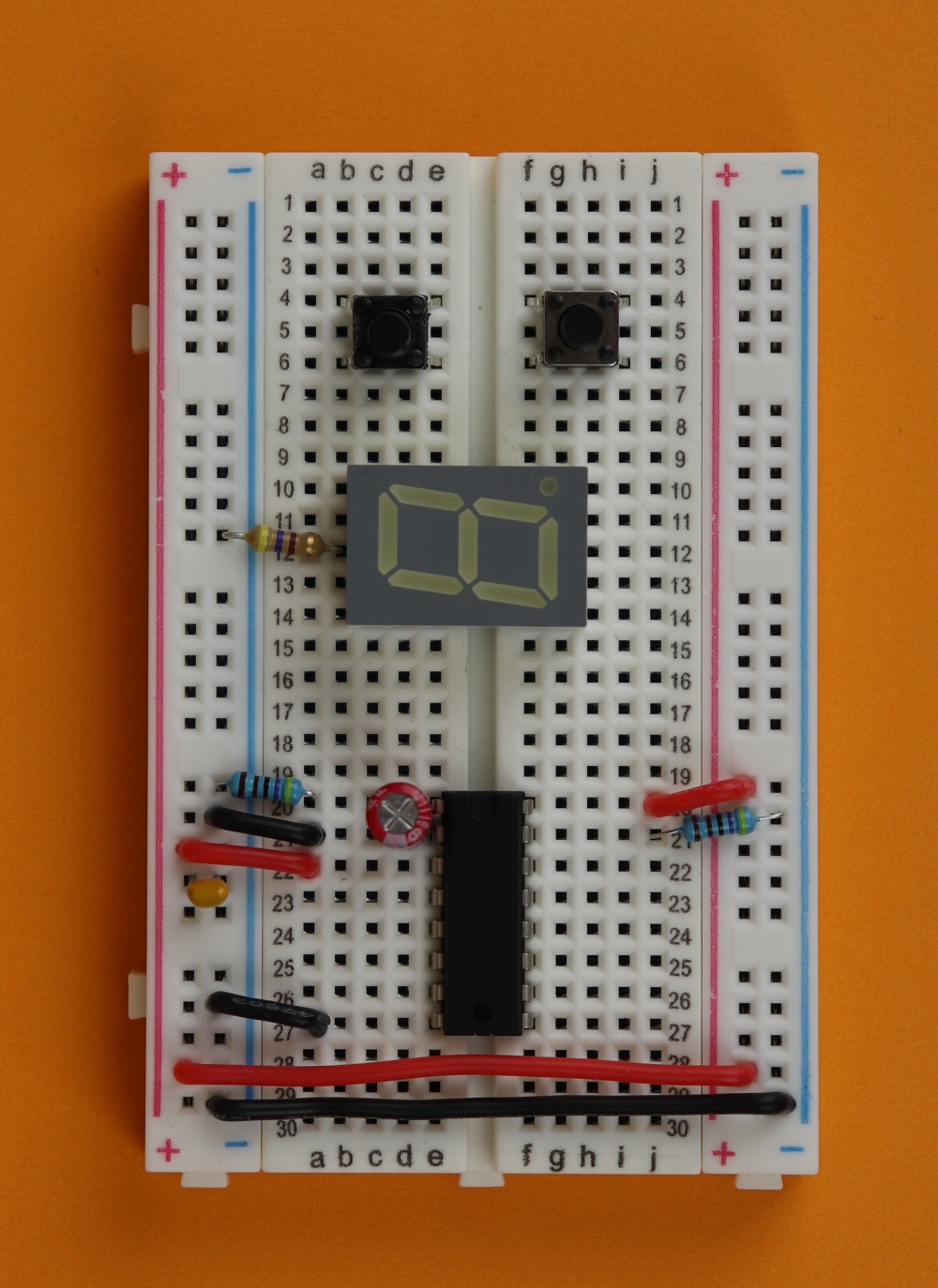
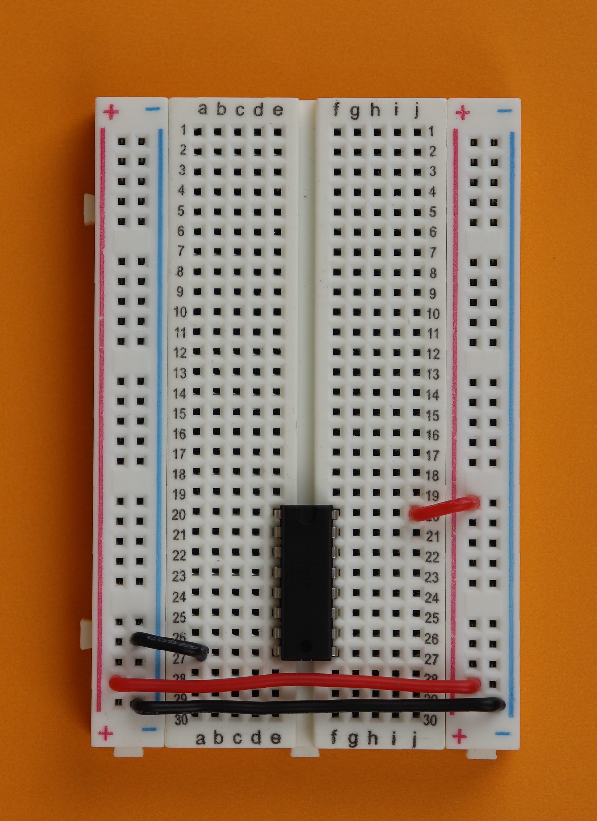
Step 3
Then place the CD4026 IC in row 20. Make sure that the notch of the IC points up towards the top of the breadboard.
-

-
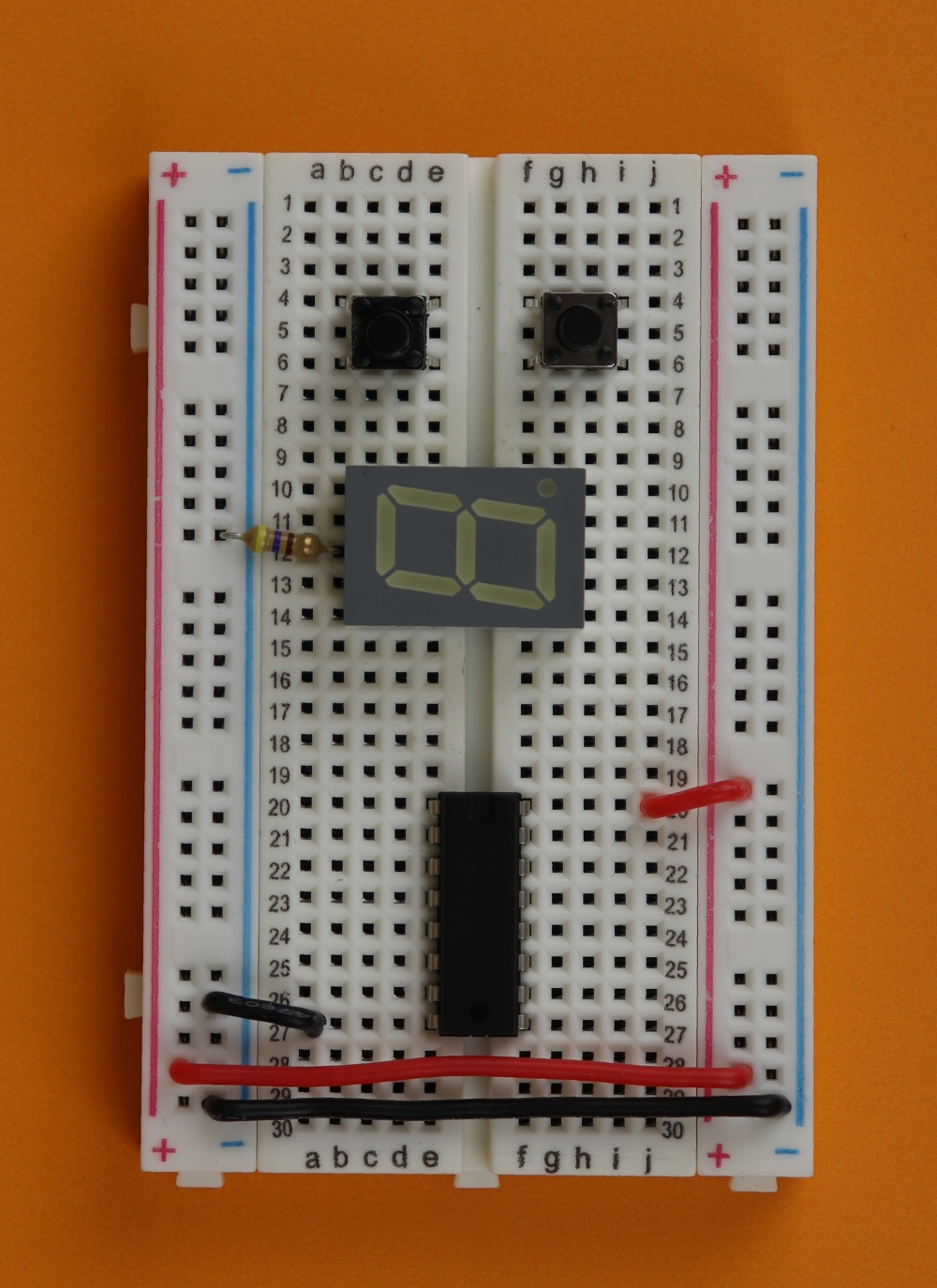
Step 4
Use two short wires to connect pin 16 (VDD) of the CD4026 to the +9V rail, and pin 8 (GND) to the ground rail.
-
-
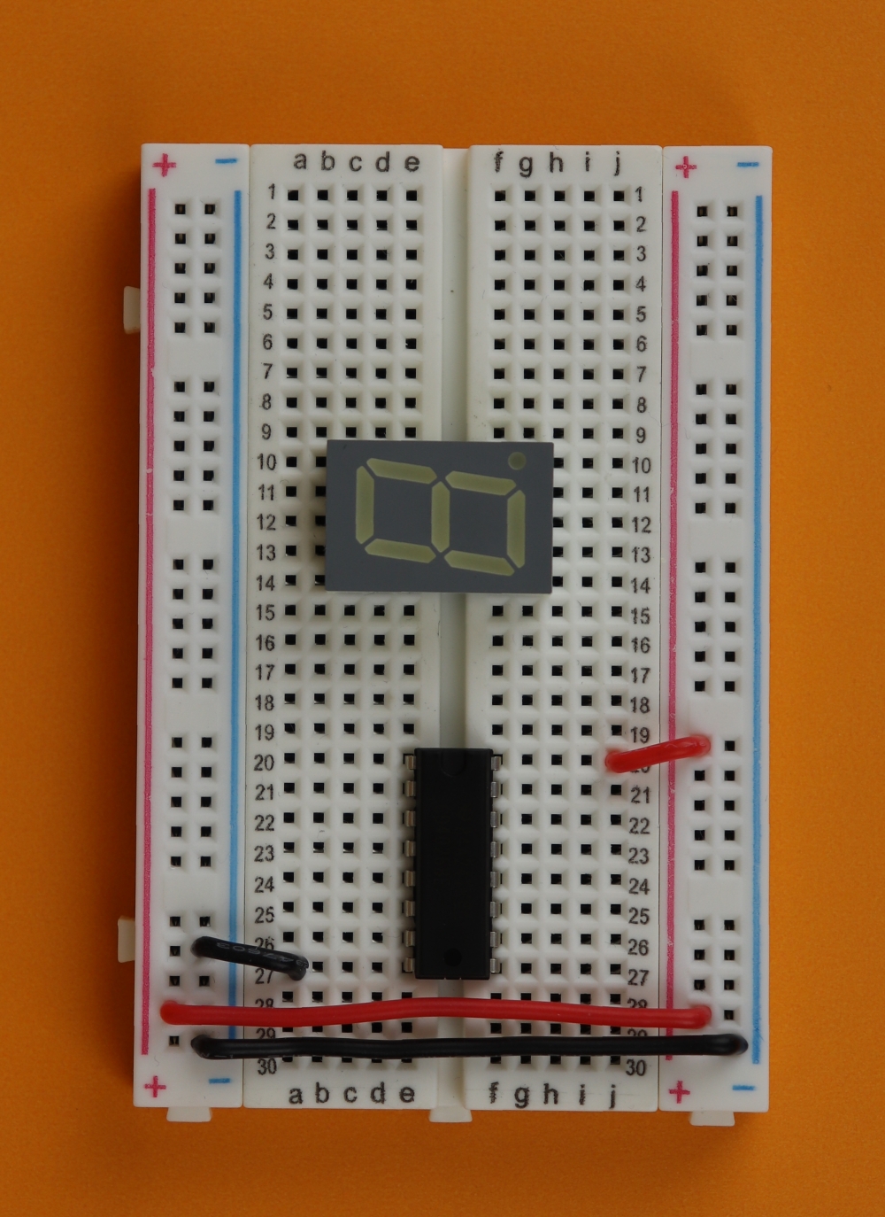
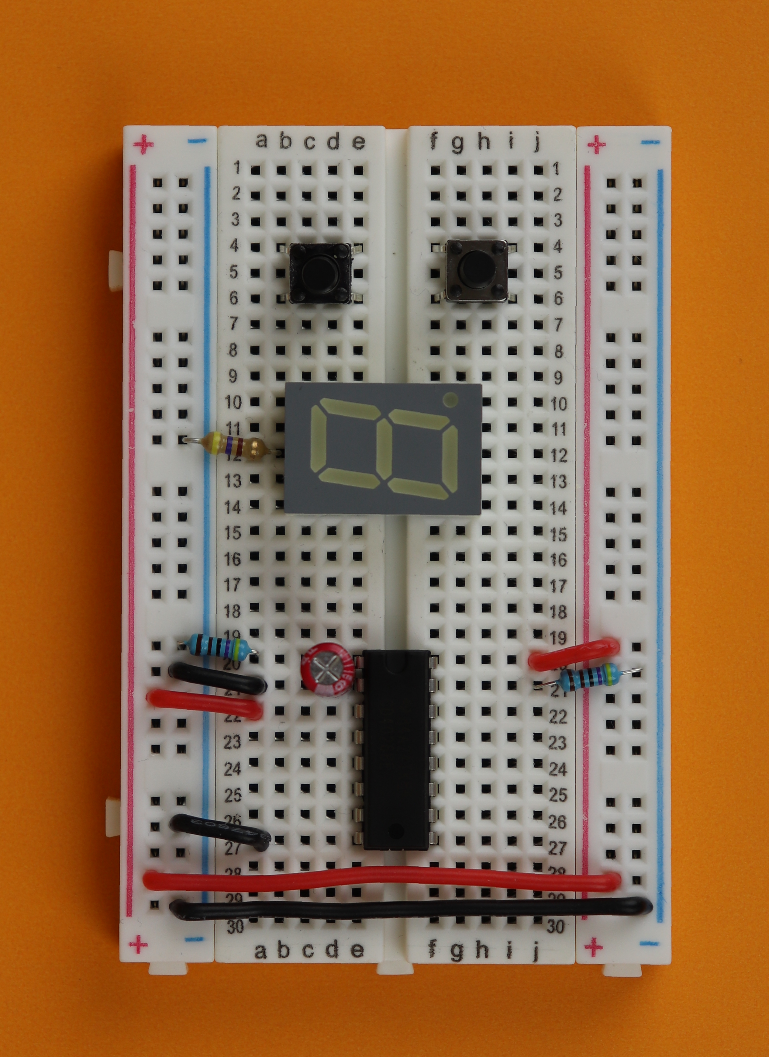
Step 5
Place the 7-segment display on the breadboard. Make sure it is a common cathode display.
-
-
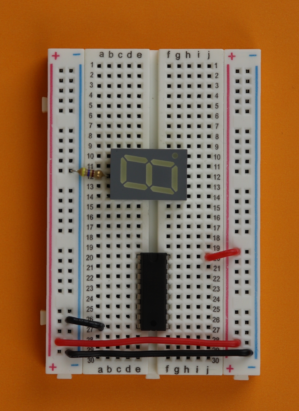
Step 6
Add the 470Ω resistor to pin 8 of the 7-segment display and connect it to ground.
-
-
Step 7
Insert the two tactile switches. There is only one orientation in which they fit into the breadboard. If they don't fit, try rotating them by 90 degrees :)
In the photo we inserted the switches in row 4 (both on the left and the right). When the left button is pressed, there will be an electrical connection between rows 4 and 6 on the left. The same is true for the button on the right. Remember that the two rows on the left and right side of the breadboard are independent.
-
-
Step 8
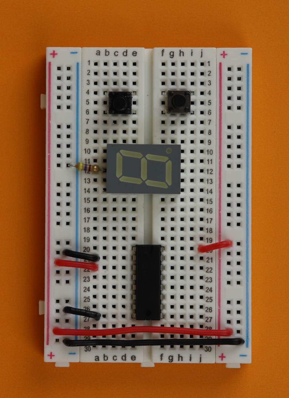
Now it's time to configure the CD4026.
Connect its pin 2 (CI, clock inhibit) to ground and pin 3 (DEI, display enable in) to the +9V rail.
-
-
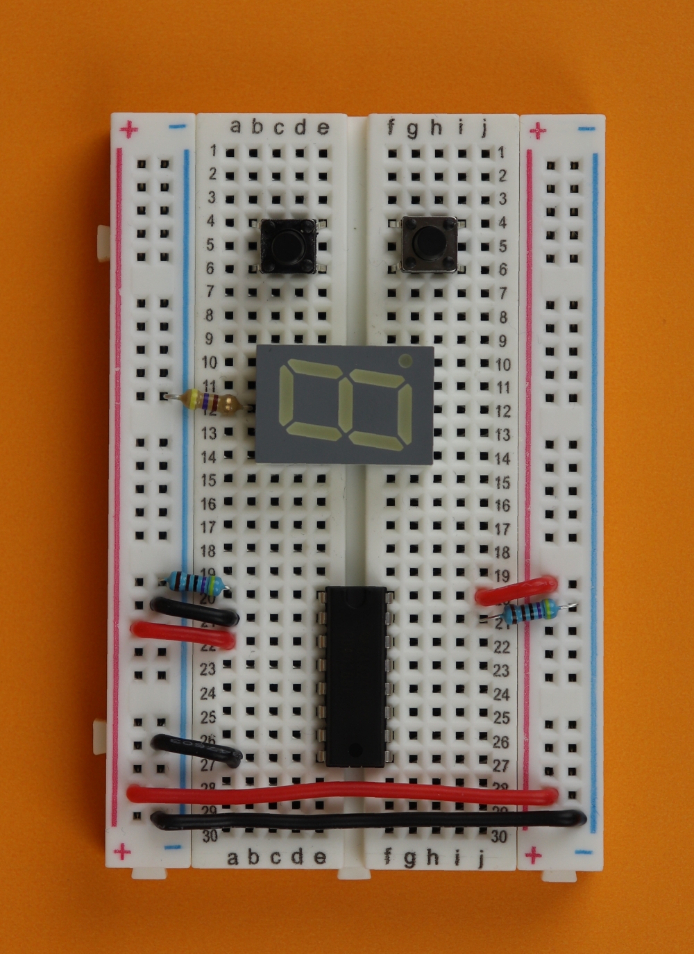
Step 9
Now we can add the pulldown resistor R1 (4.7kΩ) between pin 1 (clock) and ground, as well as the pulldown resistor R2 (4.7kΩ) between pin 15 (reset) and ground.
-
-
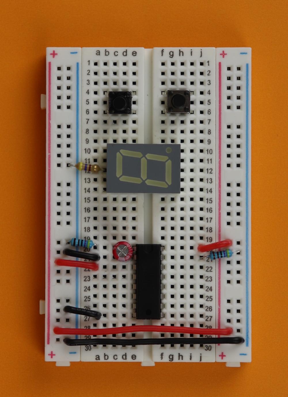
Step 10
Insert the debouncing capacitor C2 (1μF) between pin 1 (clock) and pin 2 (clock inhibit) of the CD4026.
Important: Make sure that the negative terminal of the capacitor is connected to pin 2!
-
-
Step 11
Insert the filtering capacitor C1 (100nF) somewhere close to the CD4026 in the power rail between +9V and ground.
This capacitor is not necessary when you drive the circuit via a battery, but I like to include it just in case I ever decide to run this circuit from a power supply.
-

-
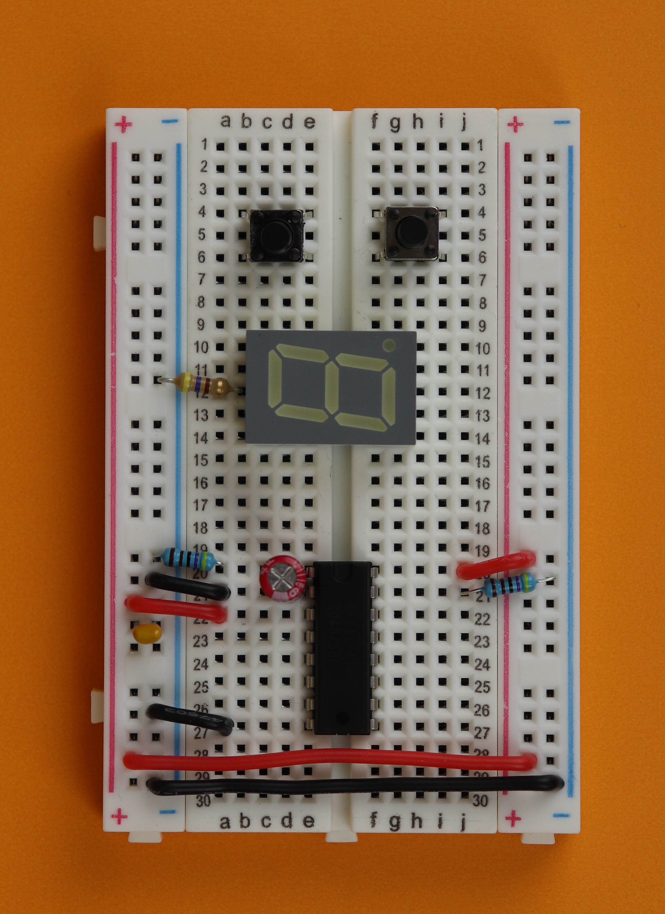
Step 12
Connect one side of each of the switches to the +9V rail.
-

-
Step 13
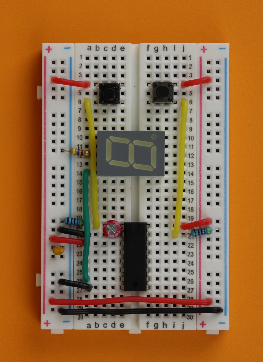
Connect the other side of the switches to the CD4026.
The left switch will increment the counter, so connect row 6 on the left to pin 1 (clock) of the CD4026.
The right switch will reset the counter, so connect row 6 on the right to pin 15 (reset) of the CD4026.
-
-
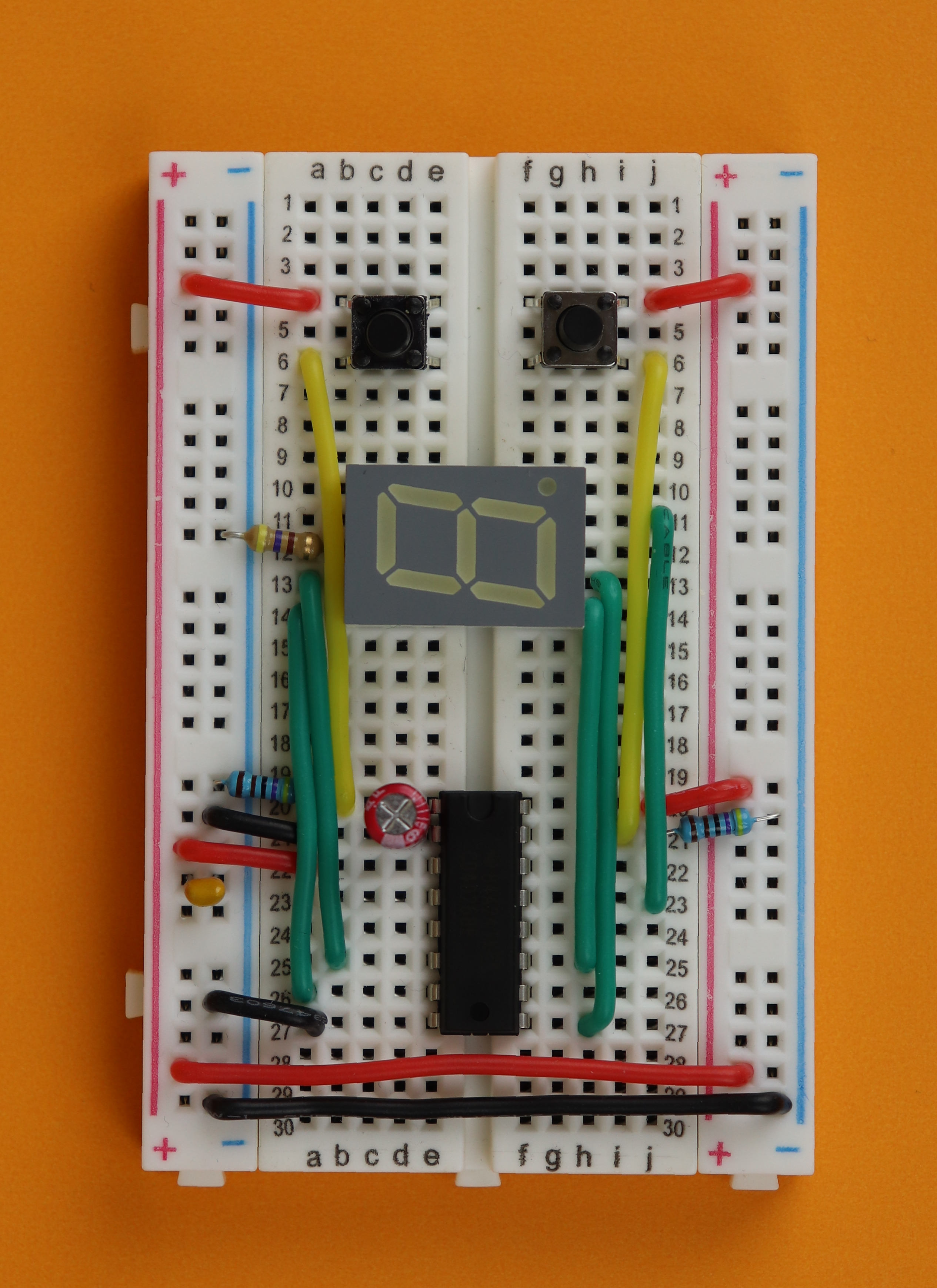
Step 14
Now it is time to connect the seven segments of the display. I do not follow the alphabetical order here (segments a through g) but a more pragmatic approach.
Connect pin 10 of the 7-segment display (row 14, left) to pin 7 of the CD4026 (row 26, left; segment g).
-
-
Step 15
Connect pin 9 of the 7-segment display (row 13, left) to pin 7 of the CD4026 (row 25, left; segment f).
-
-
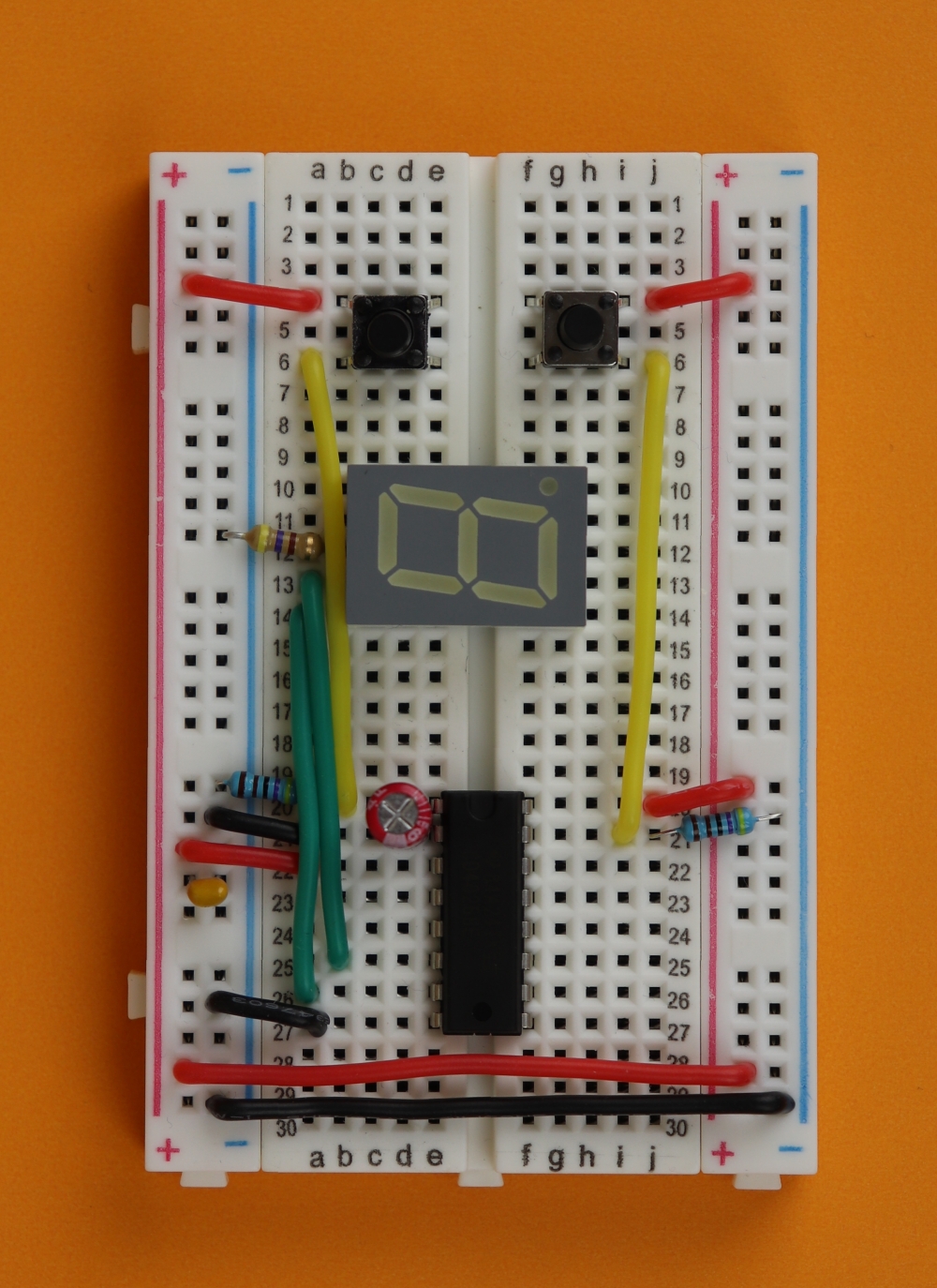
Step 16
Connect pin 2 of the 7-segment display (row 13, right) to pin 9 of the CD4026 (row 27, right; segment d).
-
-
Step 17
Connect pin 1 of the 7-segment display (row 14, right) to pin 11 of the CD4026 (row 25, right; segment e).
-

-
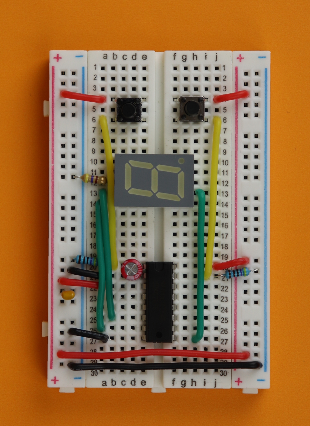
Step 18
Connect pin 4 of the 7-segment display (row 11, right) to pin 13 of the CD4026 (row 23, right; segment c).
-
-
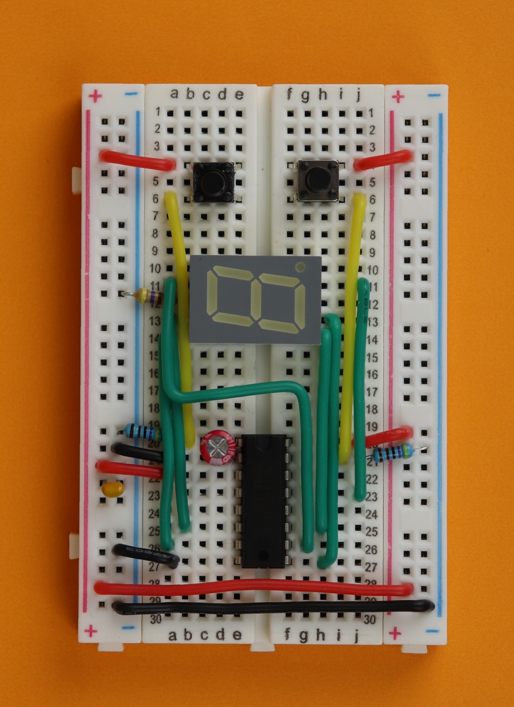
Step 19
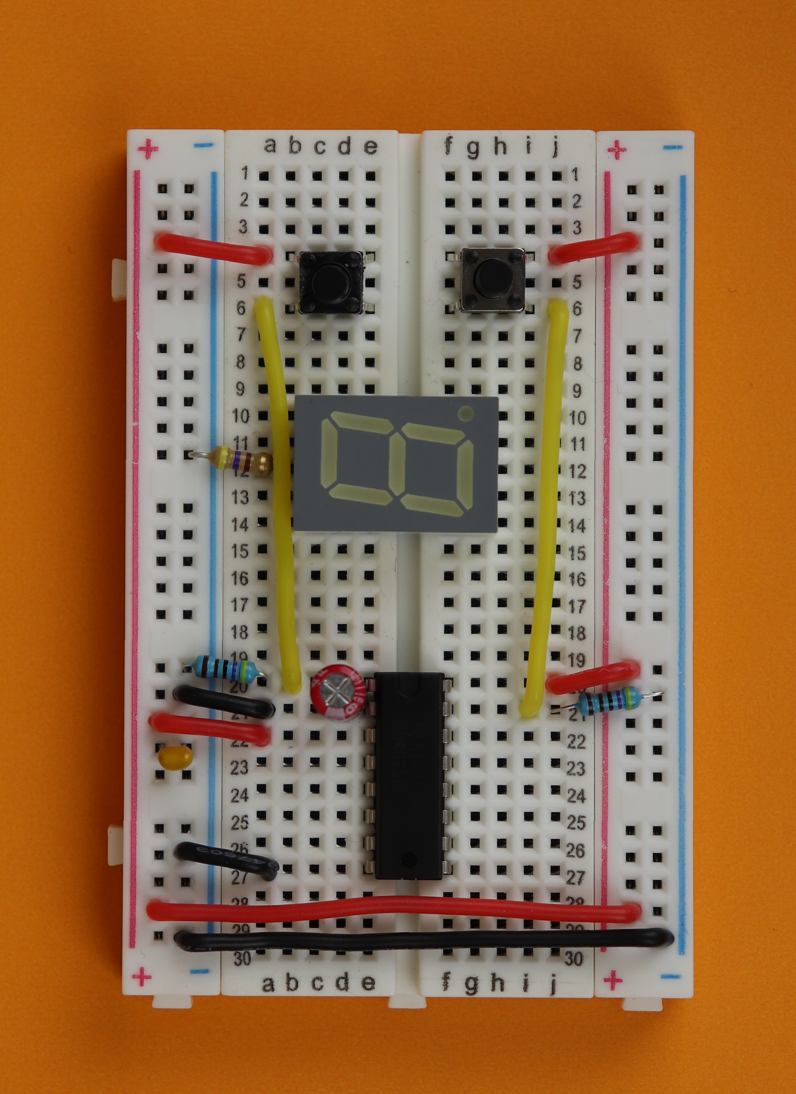
Connect pin 7 of the 7-segment display (row 11, left) to pin 10 of the CD4026 (row 26, right; segment a).
This wire is a little awkward, take some time and bend it until you like all angles and it fits nicely.
-

-
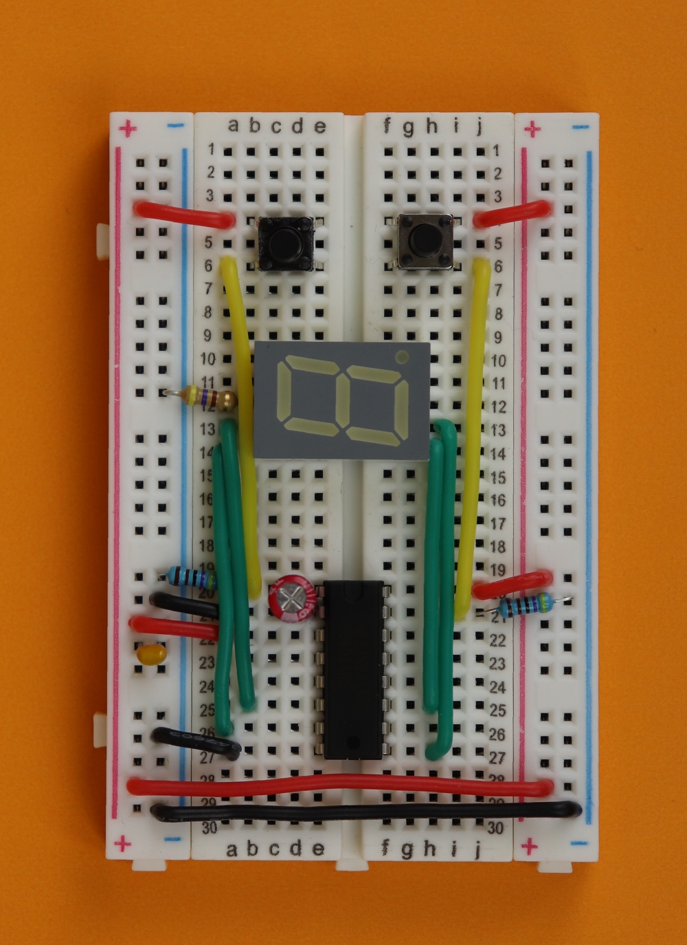
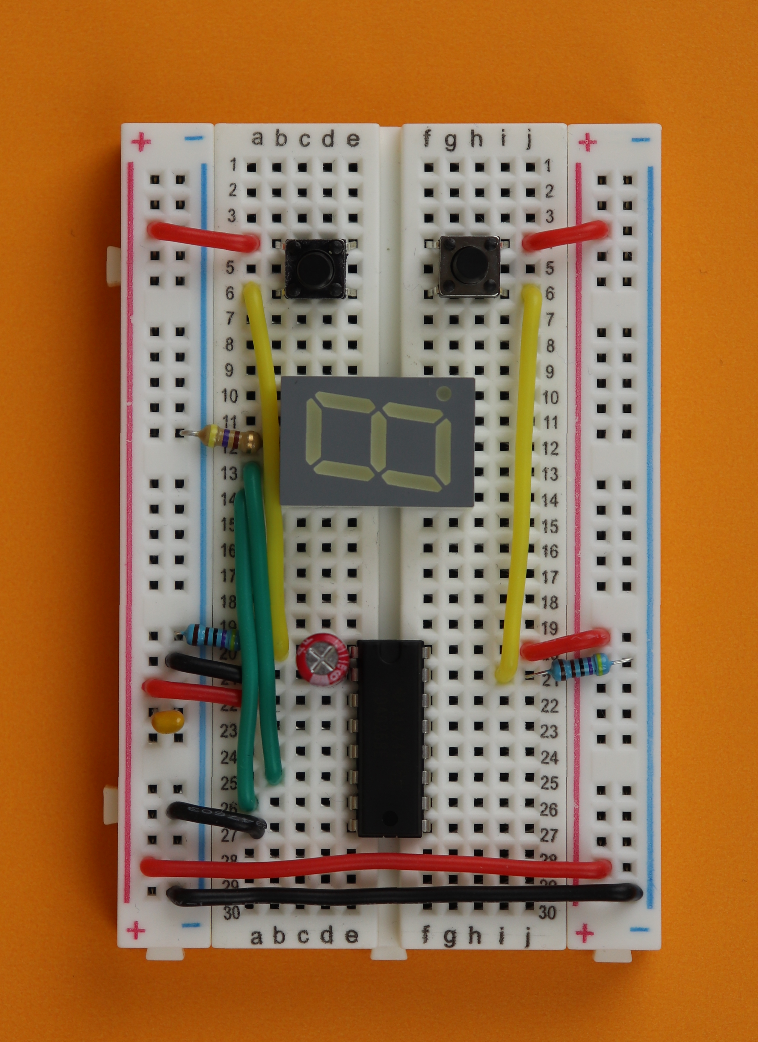
Step 20
Connect pin 6 of the 7-segment display (row 10, left) to pin 12 of the CD4026 (row 24, right; segment b).
This wire is also a little awkward, take some time and bend it until you like all angles and it fits nicely.
-

-
Step 21
We are done! Connect the red wire of the 9V clip to the +9V rail, and the black wire to the ground rail.


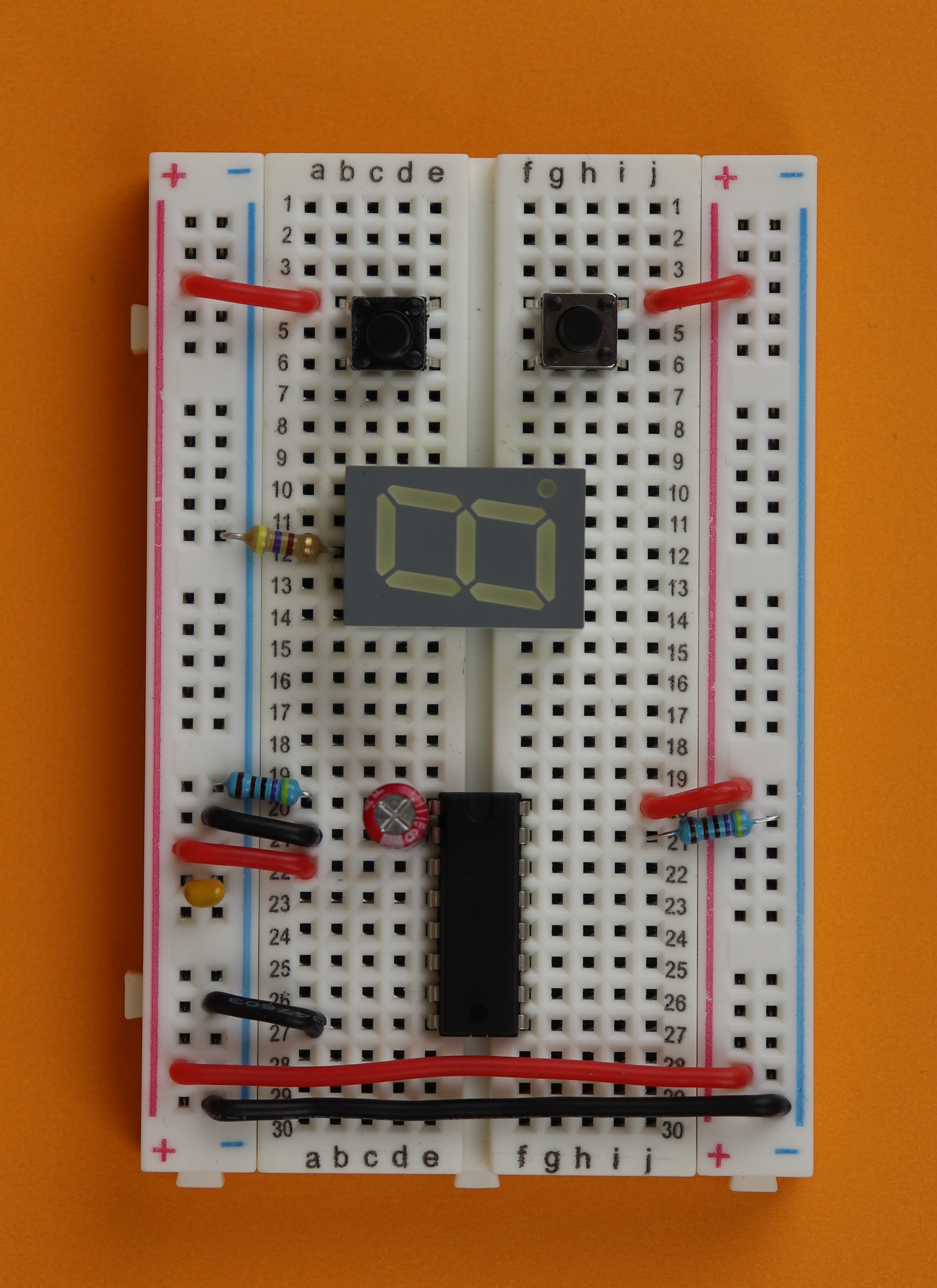

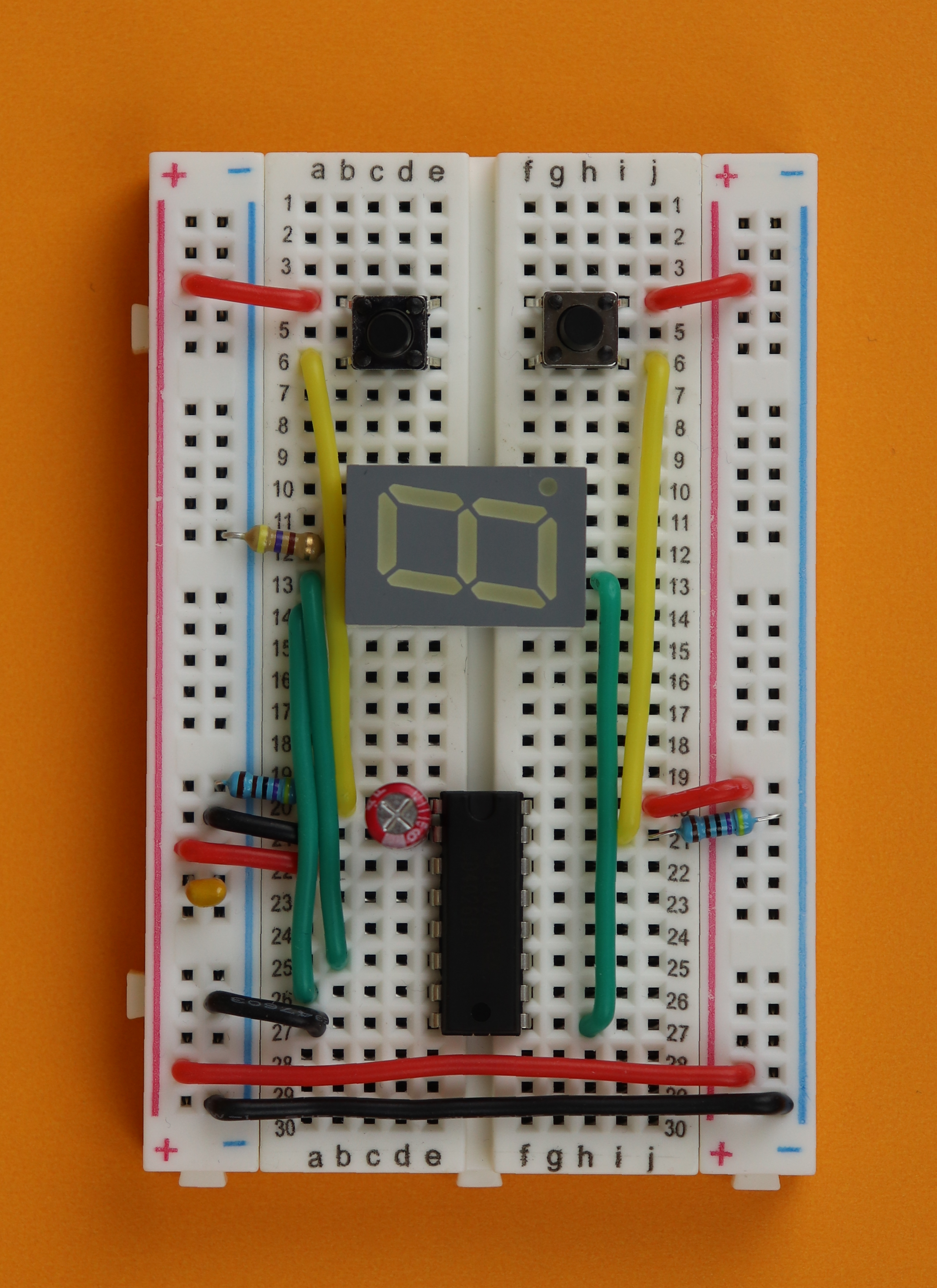


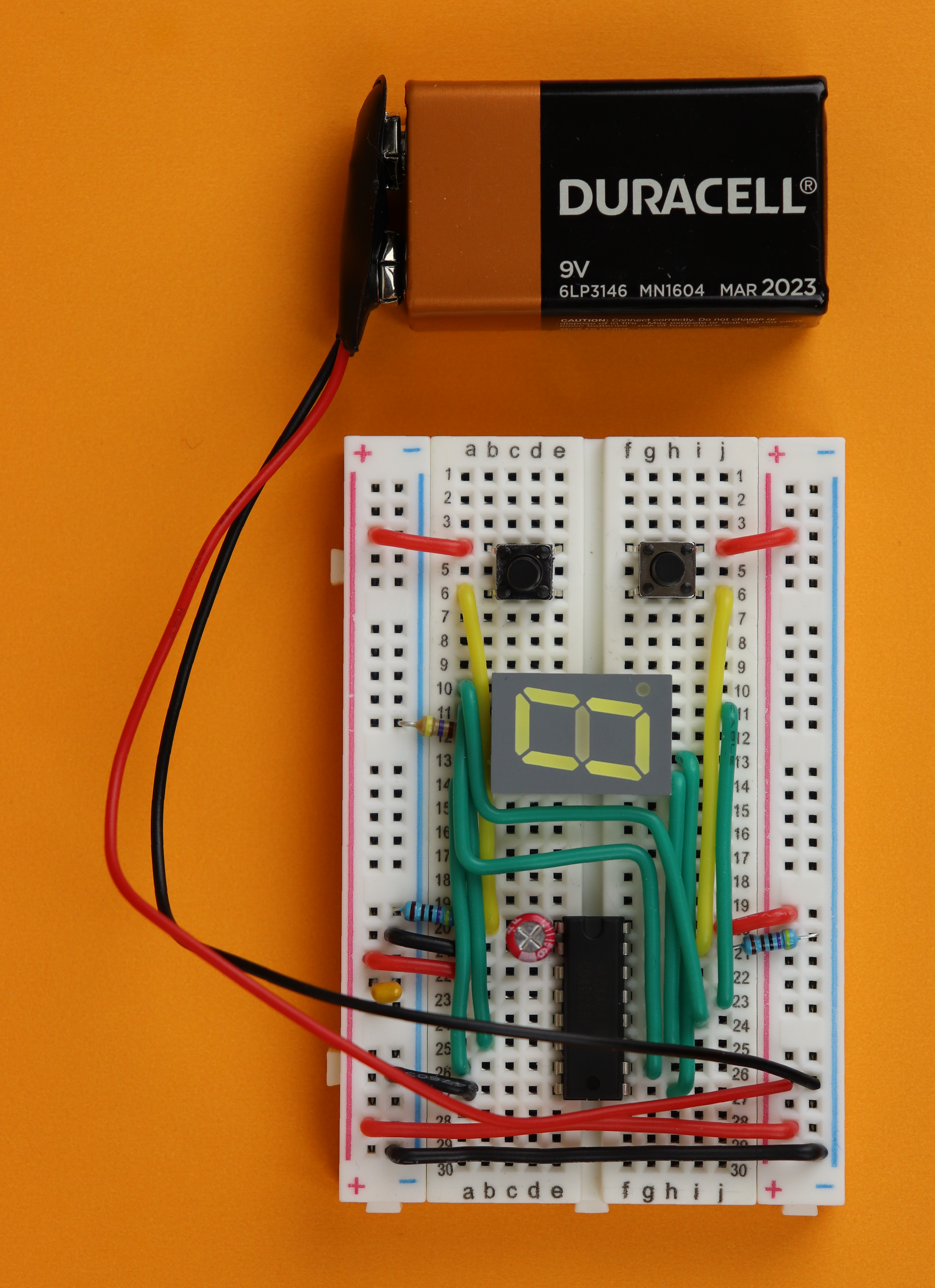
And that's it! If you press the left button, the counter should increase one by one. After it reaches 9 it goes back to zero. If you want to reset the counter, press the right button.
What if something doesn't work?
Yes, it has happened to all of us :) You build a circuit to the best of your abilities, and somehow it doesn't work. This is perfectly normal! The great thing is that it can always be fixed!
When I first built this circuit a long time ago, it didn't work and I almost gave up. I am very glad that I didn't! Eventually I figured out the problem and I got it working. So let's do the same thing here!
In the following I will list common problems with their solutions. If your circuit still does not work, get in touch on social media and we will work it out!
- Problem: The CD4026 gets warm!
Disconnect the battery, you connected it backwards! Make sure the positive terminal of the battery is connected to the +9V rail (the red one), and the negative terminal is connected to the ground rail (the blue one). - Problem: The counter does not turn on.
First, check that your battery has any juice left :) Make sure the power rails on both sides are connected properly (step 1). Also make sure that the “display enable in” pin of the CD4026 is connected to +9V (step 8). Also check if pin 8 of the 7-segment display is connected to ground via the 470Ω resistor (step 6). - Problem: The counter does not increment.
That happens a lot. Make sure that pin 2 (clock inhibit) is connected to ground (step 8). Also double check that the pulldown resistor at the reset pin (pin 15 of the CD4026) is actually connected to ground and not to +9V (step 9). Also make sure your pushbuttons work. Is the pushbutton inserted correctly? There is only one way to insert tactile switches into the breadboard, but perhaps you were overly ambitious and rammed it in? Make sure the orientation of the switch matches that of the pictures :) Sometimes (very rarely) it can happen that there is a mechanical defect in your pushbutton. If you think that is the case, remove the pushbutton and connect two wires to rows 4 and 6. Does the counter increase if you connect these wires manually? If yes, then your pushbutton is dead. - Problem: The counter does not reset.
Is the pushbutton inserted correctly? Check with the pictures (step 7) and make sure it is in the correct orientation :) Also check if the pushbutton is damaged. You can remove it and replace it with two loose wires. If you connect the wires and the counter resets, then your pushbutton is probably dead. - Problem: The counter increases by more than 1 for each button press.
This can happen when the button “bounces.” For this reason we included the capacitor C2 of 1μF. Make sure that the capacitor is connected correctly. If it is connected properly, try replacing it with a larger value of 2.2μF or even 10μF. This will limit the speed of the counter (meaning that you cannot press the button rapidly anymore) but it should do the trick. Sometimes it is also a good idea to use a different switch, because some switches are just not very good and they bounce a lot.
That's all I can think of right now. Let me know if I forgot something!
YouTube video
I covered this entire tutorial in a dedicated YouTube video:
Final thoughts
Congratulations! You built a counter, that's great!
What next? You can possibly imagine that there are many many different applications for counters out there. Here are a few possible ideas:
- You can cascade counters in series, so instead of counting from 0-9 you will be able to count from 0-99. This can be done by connecting CO (carry out, pin 5) to the CLK (clock, pin 1) of a second CD4026 counter, and so on. That second counter then displays the tens.
- What if you only want to count to, say, 7 instead of 9? You can use CMOS logic gates to check the output for a certain number and connect that to the reset pin (pin 15).
- If you connect the clock pin to a 1Hz signal, cascade the counter with another one, and reset it at 60, you have basically built 1/3 of a clock! You can then duplicate this stage for the minutes, and built a third stage that resets at 24 to complete the clock.
- I am pretty sure there is much more that can be done!
As much fun as that is, we will leave these ideas for the future. The idea of this tutorial is to get you interested in electronics, and I hope I could convince you that electronics is a lot of fun.
If you stick around we can tackle more advanced projects :) Thank you so much for tuning in, I will see you around!


