A realistic, flickering electronic candle
December 15, 2019 • project
It's winter, it's getting cold outside, so let's light up an electronic candle to fill our hearts and houses with warmth! This project will teach us a lot about generating random numbers on a microcontroller with an analog to digital converter and controlling LED brightness via pulse-width modulation. So let's get started!
Before we jump in I just want to mention that this project is very simple on the electronics side, but a bit heavy on the software side. So it helps if you have read these previous articles:
- How to “flash” a PIC microcontroller?
- How to adjust LED brightness with a PIC microcontroller
- Understanding analog to digital converters
If you did not have time to read it, that's OK! This project tries to be as self-contained as possible :)
What do you need?
The amount of components needed for this project is quite small, you can find a detailed list in the components box. The main tool we need is the PICkit3 to flash our microcontroller with the candle program, and you can find more information about that in the tools box.
Here is a picture of all components:
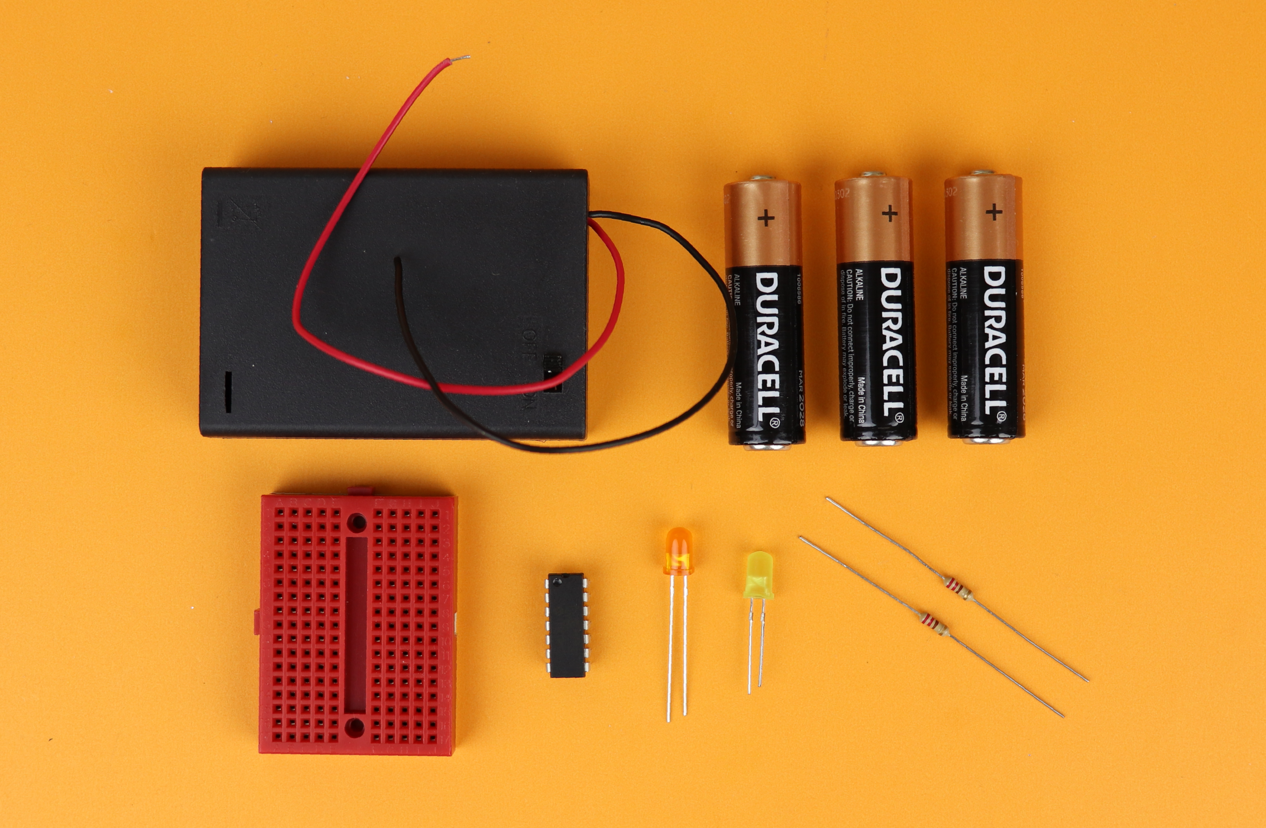
And yes, that's really all! For this project the magic happens inside the microcontroller, and more on that below!
The schematic
This is the schematic for the electronic candle:
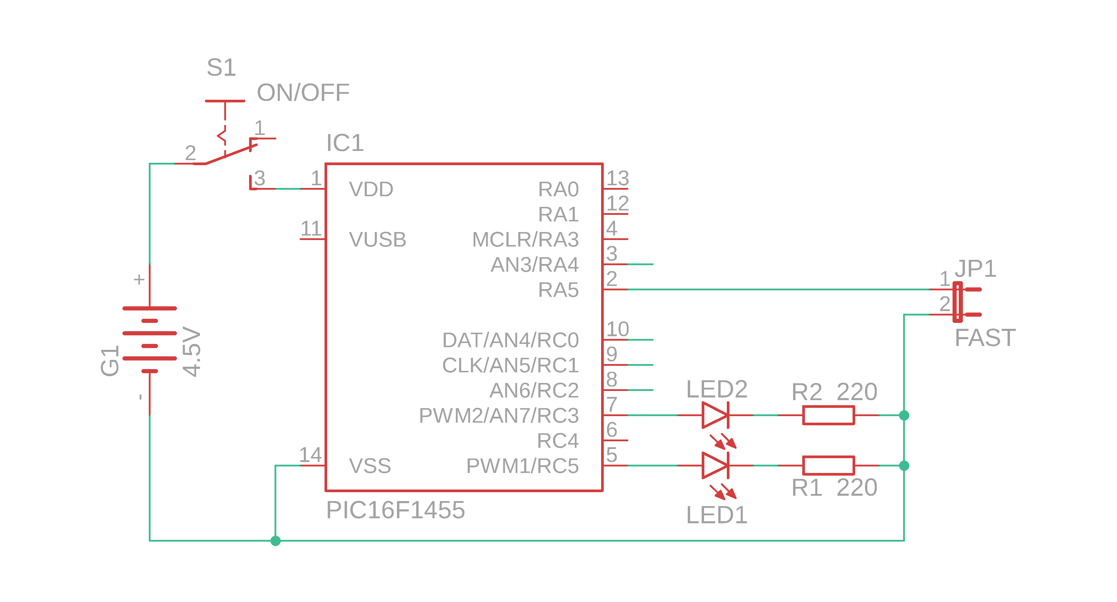
As you may have already guessed from the rather short list of components: the schematic is super simple! It is based on the PIC16F1455 PIC microcontroller made by MicroChip. This controller is what they call an “enhanced mid-range” controller, which is really a funny name if you ask me. What it means is that it has advanced features that other controllers of the PIC16F-series typically don't have. In our case I chose this controller because it has the following nice features:
- Two pulse-width modulation (PWM) channels with a resolution of 10 bit (which allows us to animate the brightness of two LEDs as opposed to just one).
- Five analog to digital converter (ADC) channels with a resolution of 10 bit. The high resolution is essential for a nice flickering flame animation, as we will learn below :)
- An internal oscillator that can be used instead of an external crystal, which helps us cut down on the number of external components.
Okay, so how does the schematic work? The PIC16F1455 controls the brightness of LED1 and LED2 via the two PWM channels PWM1 and PWM2 at the ports RC5 and RC3, respectively. The whole circuit is powered by a 4.5V battery power supply that can be connected and disconnected via the switch S1.
The funny looking symbol JP1 is a jumper, and jumpers usually can be open or closed. In this project we can connect the pin RA5 to ground by closing the jumper JP1. If we close the jumper, the PIC16F1455 realizes that and the software will switch the animation mode of the candle from a calm, slow mode, to a faster, more rapid mode.
What about the unconnected wires at RA4, RC0, RC1, and RC2? This is done in purpose, and we will use these floating inputs of the ADC to generate random numbers, see below. And that's it! Now let's talk about the software, and how we use the ADC to create a realistic flickering flame animation!
Realistic flickering & random numbers
What makes candle light so special? Personally, I think it is a combination of the color temperature as well as the brightness variations (“flickering”). We can control the color temperature by choosing appropriate LEDs (and I suggest a combination of red/orange/yellow/warm white), so the true challenge here is to create the illusion of a flickering flame with electronics.
There are many cheap electronic candles out there, and I always find that their flickering just doesn't look very realistic. Sometimes there is a pattern that repeats itself, and some other time there are just not enough variations in brightness.
A real life candle flickers because of small fluctuations in the air that surrounds it. A bit of wind, a bit of a convective stream, and the flame moves and varies in brightness. This change of brightness is essentially chaotic and random, and in practice it is impossible to predict.
When we want to create a random variation in LED brightness with a microcontroller there is a big problem: it is fundamentally impossible to create truly random numbers on a fully deterministic machine!
There are no random numbers in a microcontroller!
How can we cheat and create random numbers anyway? This is where the analog to digital converter (ADC) comes in! If we leave the input for the ADC channels open, they will essentially measure noise. And the least significant bits (also called LSBs, read more about binary here) will fluctuate. We have all seen it: if you leave a multimeter disconnected, it does not just show zero. It actually shows small values close to zero.
By taking the least significant bit of four of the ADC channels we essentially have four random numbers that are either 0 or 1. Let's call these numbers N1 to N4. When we add them up like this, we end up with a random number between 0-15:
rnd = 8×N4 + 4×N3 + 2×N2 + N1
So rnd can take values between 0 and 15. When we multiply this number by 16, for example, we find that the total number, call it rnd', can be between 0 and 240 (in increments of 16):
rnd' = 16 × ( 8×N4 + 4×N3 + 2×N2 + N1 )
The idea is now that we use this number as a seed for our electronic candle, and we let this number control the brightness of the LEDs by using it as the duty-cycle value (learn more about duty-cycle values and pulse-width modulation here). Together with some loops and counters we can create almost life-like brightness variations of our electronic candle that come very close to an actual flickering candle.
Now that we understand the main idea, let's take a closer look at the source code.
The source code
Alright, let's go! You can find the full C source code in the appendix and you can also download it as well as the .hex file in the resources box. If things like .hex file or source code don't mean anything to you, go check out the first PIC microcontroller project we ever talked about, it has lots of useful information :)
We won't go through every single line of the source code, but I made sure to add many comments in the file itself. Here we will focus on these four main points:
- Setting up the internal oscillator to 4MHz, weak pull-up for RA5, and activating TIMER1.
- How do we set up the ADC and the PWM modules?
- How do we generate random numbers from the ADC?
- And how is that useful in generating a flickering pattern for the candle?
If there is anything that is entirely mysterious, make sure to get in touch on social media and we can work it out :)
	// set internal oscillator to 4MHz
    IRCF0 = 1;
    IRCF1 = 0;
    IRCF2 = 1;
    IRCF3 = 1;

    // weak pull-up for jumper
    TRISA5 = 1;
    WPUA5 = 1;
    nWPUEN = 0;

    // TIMER0 settings

	// internal clock, no prescaler, interrupt on overflow
	TMR0CS = 0;
	PSA = 1;
	TMR0IE = 1;

	// enable global interrupts
	GIE = 1;
- In lines 45-49 we set the internal oscillator to 4MHz. We could set it to a faster speed, but that is not really necessary, and since our circuit will run on batteries it is a good idea not to waste too much juice on a faster clock speed. The nice thing about internal oscillators is that you save the external crystal and capacitors.
- Microcontroller pins, when configured as digital inputs, should always be on a defined logical level. According to the schematic, input RA5 is unconnected whenever the jumper JP1 is not closed. We would have to install a manual pull-up resistor. Luckily, the PIC16F1455 has individually switchable pull-up resistors for many ports, including the port RA5. In lines 51-54 we first set port RA5 to be an input, then activate its weak internal pull-up (that is where the abbreviation WPUA5 comes from), and then enable the weak pull-ups by clearing the register
nWPUEN. The lower case “n” signified that this register is inverted: the weak internal pull-ups are enabled if the register is set to zero (and are disabled it it is set to 1). - In lines 56-64 we first turn on TIMER1, and then tell the controller to trigger an interrupt whenever the timer overflows. At the settings above, and at the clock frequency of 4MHz, this happens around 4000 times per second. It is not important that it is exactly 4000 times, plus or minus a few dozen does not matter since our candle is not time-sensitive. This just sets an approximate time scale for our candle flicker animation. If you want to learn more about interrupts you can read the article on how to generate a 1Hz signal with the PIC16F627A: this article is written for a different controller, but the idea is exactly the same.
Now that this is taken care of, we can initialize the ADC module:
    // ADC settings

	// ADC sampling frequency per bit is F_osc/2
	ADCS0 = 0;
	ADCS1 = 0;
    ADCS2 = 0;

    // result alignment
    ADFM = 1;

	// RA4, RC0, RC1, RC2 ports as analog inputs
	TRISA4 = 1;
    TRISC0 = 1;
    TRISC1 = 1;
    TRISC2 = 1;
    ANSA4 = 1;
    ANSC0 = 1;
    ANSC1 = 1;
    ANSC2 = 1;

	// turn the ADC on
ADON = 1;- In lines 68-71 we set the sampling frequency of the ADC per bit of resolution. Since the resolution of our ADC is 10 bit, the total sampling frequency will be one tenth of that. I chose the highest value possible allowing for the fastest conversion because this way we can maximize the inaccuracy in the lowest digits. It is ironic, but in this case we want the accuracy to be as bad as possible so that we can create some nice random numbers from the ADC noise.
- Lines 73-74 specify how the 10 bit ADC conversion result is divided into the two 8-bit registers
ADRESHandADRESL(see also page 156of the datasheet). This detail is important because we need to be able to extract the zeroth bit, and we need to know where to look for it. In this case, it is stored in the zeroth bit ofADRESL. - We also need to turn on the ADC functionality by switching the corresponding ports into “analog mode.” Lines 76-84 do exactly that for the ports RA4, RC0, RC1, and RC2.
- Now we are ready to turn the ADC module on in lines 86-87.
Since we want to dim the LEDs to simulate a flickering candle we also need to set up the 10-bit PWM modules. And yes, the PIC16F1455 has two independent modules! The names of the registers are slightly different from when we first learned about PWM with the PIC16F627A, but the principle is the same:
	// PWM settings

    // ports
    TRISC5 = 0;
    TRISC3 = 0;

    // configure TIMER2
    PR2 = 0xff;
    T2CON = 0b100;

    // turn on PWM modules
    PWM1EN = 1; PWM1OE = 1;
    PWM2EN = 1; PWM2OE = 1;
- Lines 91-93 set the two PWM module ports RC5 and RC3 as outputs.
- In lines 95-97 we set the resolution for our PWM modules to 10 bit and the PWM frequency to around 4kHz by adjusting the upper limit as well as the prescaler of TIMER2.
- Then we can turn the PWM modules on in lines 99-101 and enable their outputs.
Next, let's have a look at the main loop of the program:
	// main loop
    while (1) {

        // enable fast mode if the jumper
        // is connected to ground
        if (JP_fast) {
            mode = 0;
        } else {
            mode = 1;
        }

		// fast or slow?
		if (mode == 0) {
			maxValue = 200;  mean_values = 1;   fade_delay = 0;
		} else if (mode == 1) {
			maxValue = 250;  mean_values = 16;  fade_delay = 4;
		}

		// the actual animation
		if (newValue1 >= maxValue) {
			rnd = 0;
			for (t = 0; t < mean_values; t++) {
				rnd += getRandomNumber();
			}
			random_number1 = rnd / t;
			newValue1 = 0;
		}
		if (newValue2 >= maxValue) {
			rnd = 0;
			for (t = 0; t < mean_values; t++) {
				rnd += getRandomNumber();
			}
			random_number2 = rnd / t;
			newValue2 = 0;
		}

    }
- Lines 106-112 are quite simple: they just check whether jumper JP1 is closed or not. If it is, it sets the mode to “fast,” and if it isn't, the mode remains at “slow.”
- In lines 114-119 the animation parameters are set according to the previous selection via the jumper. We will talk about the meaning of these values later.
- Then, in lines 121-129 as well as in lines 130-137 two random numbers are generated (one for each channel). Let us focus on lines 121-129, because the other lines are identical. First, the random number variable
rndis reset. Then, depending on the value ofmean_values, a certain number of these random numbers are averaged. The higher the variablemean_values, the less the final result will fluctuate. These lines are only executed every once in a while, namely, whennewValue1exceeds a certain maximum value. This way we can control the animation speed.
The animation is timed via the interrupt service routine (about which you can read more here if you want). It is basically a function that is called around 4000 times per second, and we configured this in lines 56-64. Here is what this interrupt service routine does:
// the interrupt service routine
void __interrupt () isr (void) {

	if (TMR0IF) {

        // animation
		newValue1++;
        newValue2++;
		speed1++;
        speed2++;
		if (speed1 >= fade_delay) {
			if (PWM1DCH > random_number1) {
				PWM1DCH--;
			} else if (PWM1DCH < random_number1) {
				PWM1DCH++;
			}
			speed1 = 0;
		}
		if (speed2 >= fade_delay) {
            if (PWM2DCH > random_number2) {
				PWM2DCH--;
			} else if (PWM2DCH < random_number2) {
				PWM2DCH++;
			}
            speed2 = 0;
        }

		// reset interrupt flag
		TMR0IF = 0;

	}

}
- In line 148 we check whether TIMER1 has overflowed. If so, the rest of the function is executed. This guarantees that this function is called around 4000 times per second.
- Lines 150-154 simply increase some book-keeping variables that keep track of the stage of the animation.
- Lines 155-162 (and lines 163-170) contain the actual animation for LED1 (and LED2). The variable
fade_delaycontrols how long a given random brightness for an LED is held, before it is then slowly increased all the way to the random number, or all the way back to zero. - In line 173 we reset the interrupt flag of TIMER1. This is very important, because if we didn't do this, the controller would get stuck in this interrupt service routine (and not just call it 4000 times per second, but all the time). We don't want this, so we clear the flag.
We are almost done. All that remains is the generation of the random number that we already talked about above. The following code is just the implementation of that idea in C:
// this method creates a random number between 0 and 240
unsigned char getRandomNumber () {

	unsigned char tmp = 0;

    // read channel AN3
    CHS0 = 1; CHS1 = 1; CHS2 = 0; GO = 1; while (GO);
	tmp = ADRESL & 1;

    // read channel AN4
    CHS0 = 0; CHS1 = 0; CHS2 = 1; GO = 1; while (GO);
	tmp += (ADRESL & 1) << 1;

    // read channel AN5
    CHS0 = 1; CHS1 = 0; CHS2 = 1; GO = 1; while (GO);
	tmp += (ADRESL & 1) << 2;

    // read channel AN6
    CHS0 = 0; CHS1 = 1; CHS2 = 1; GO = 1; while (GO);
	tmp += (ADRESL & 1) << 3;

    // multiply result by 16 to create a random number between 16 and 255
	return (tmp << 4);

}
- This function is rather simple. In line 182 we reset the variable that will contain our random number later.
- Then we generate four random bits by starting an ADC conversion at each of the floating ADC inputs. Remember that the least significant bit is stored in bit 0 of the register
ADRESL. So whenever we writeADRESL & 1we extract the value of that bit. - At each stage (line 186, 190, 194, 198) this bit is multiplied by 1, 2, 4, and 8 and added to the total random number. Then, in line 201, we multiply everything by 16 and thereby create a random number between 0 and 240. I hope this makes sense :) The idea of this is exactly as we talked about above.
And that's the code! Now we can compile this code in the free MPLAB X Integrated Development Environment and generate a .hex file that we can then flash onto the PIC16F1455.
Flashing the .hex file onto the PIC16F1455
Now that we have compiled the C source code and obtained a .hex file, we have to flash that .hex file onto the PIC16F1455 using the PICkit3 that works great with the MPLAB IPE that comes with the MPLAB X IDE. If this sounds confusing to you, go and have a look at our first-ever PIC microcontroller project that explains the basics :)
In order to flash the PIC16F1455 all we need to do is connect the following pins to the PICkit3:

- MCLR is located at the leftmost pin of the PICkit3 and corresponds to pin 4 of the PIC16F1455.
- VDD and VSS are pins 2 and 3 of the PICkit3, and pins 1 and 14 on the PIC16F1455. They are just the power supply connections.
- PGD/DAT is the data pin. On the PICkit3 it is pin 4, and on the PIC16F1455 it is pin 10.
- PGC/CLK is the clock pin. On the PICkit3 it is pin 5, and on the PIC16F1455 it is pin 9.
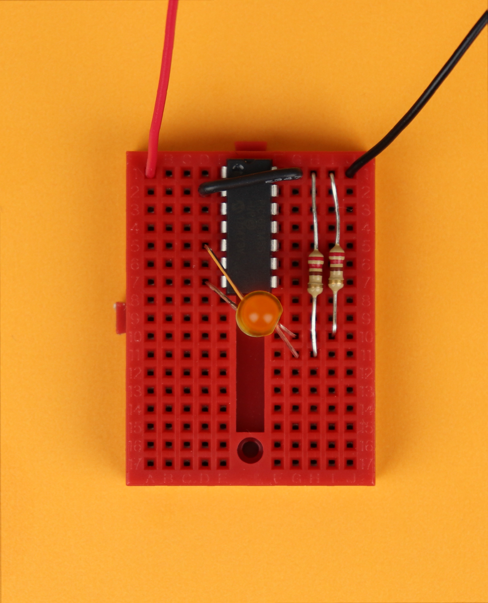
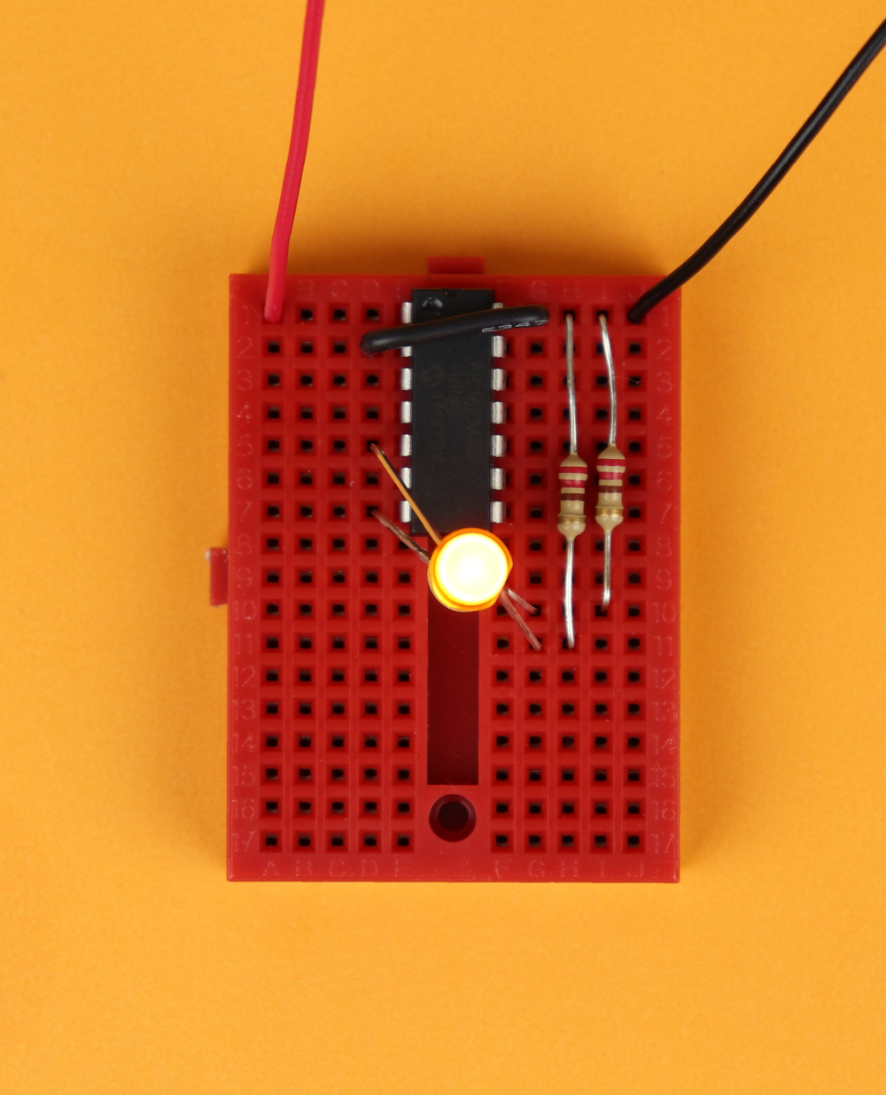
On the bottom right you can see our breadboard that we can use to flash the PIC16F1455. When connecting to the MPLAB IPE make sure to select “Power target device from tool:”
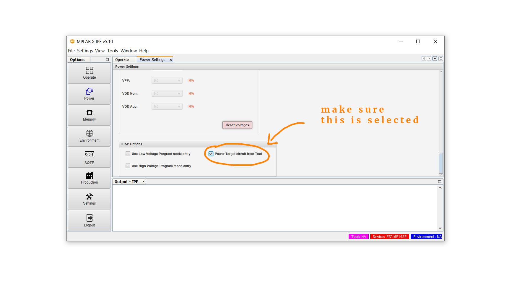
Then, click on connect, select your .hex file, and click on program. Done!
Building the electronic candle
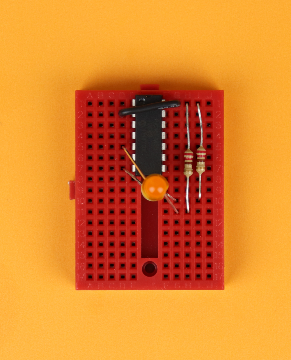
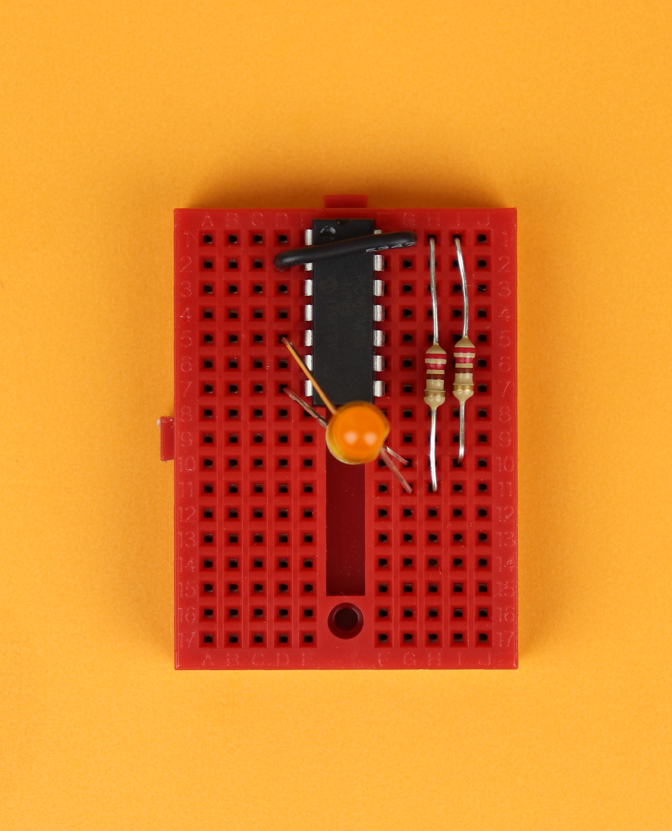
Now you can remove your freshly flashed PIC16F1455 from the breadboard and start building!
-

-
Step 1
Place the 170-pin breadboard in front of you :)
-

-
Step 2
Place the PIC16F1455 in row 1, and make sure that its notch points up.
-

-
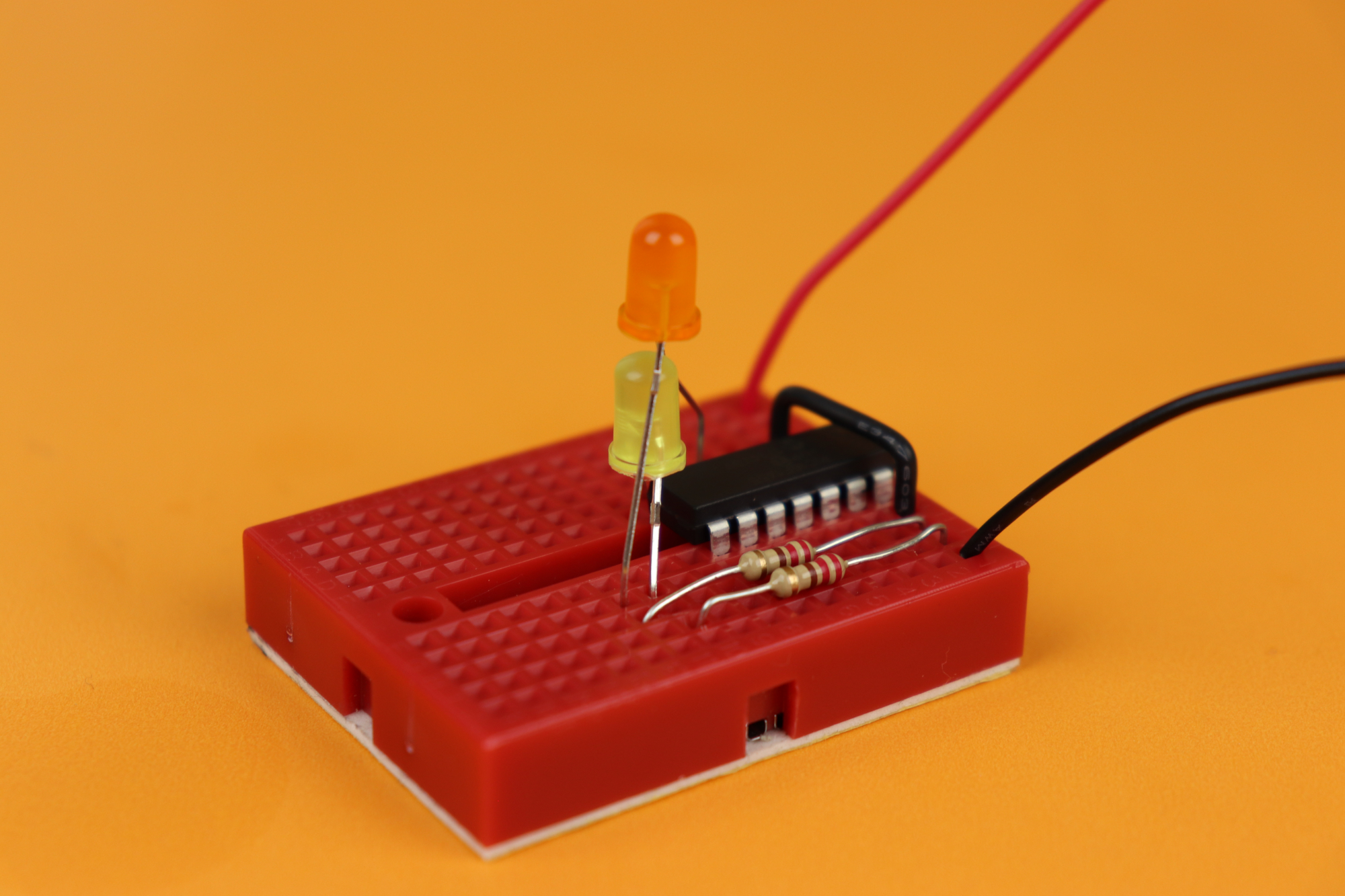
Step 3
Insert the two 220Ω resistors as shown in the picture. Remember that pin 14 (the top right pin) if the PIC16F1455 is ground, and these resistors therefore connect to ground as well.
-

-
Step 4
This step is optional.
Close the jumper JP1 between pins 2 and pin 14 of the PIC16F1455 if you want the fast LED animation. If you want the slow animation instead, skip this step.
-

-
Step 5
Place LED2. Its anode is connected to pin 7, and its cathode is connected to one of the resistors we previously inserted.
-
-
Step 6
Insert LED1, on top of LED2. Its anode is connected to pin 5, and its cathode is connected to the remaining resistor.
-
-
Step 7
Now we are all set, and you can connect the positive battery power to pin 1 of the PIC16F1455, and the negative terminal to pin 14.
-
-
Step 8
All done! When you switch on the battery power, the LEDs will light up!


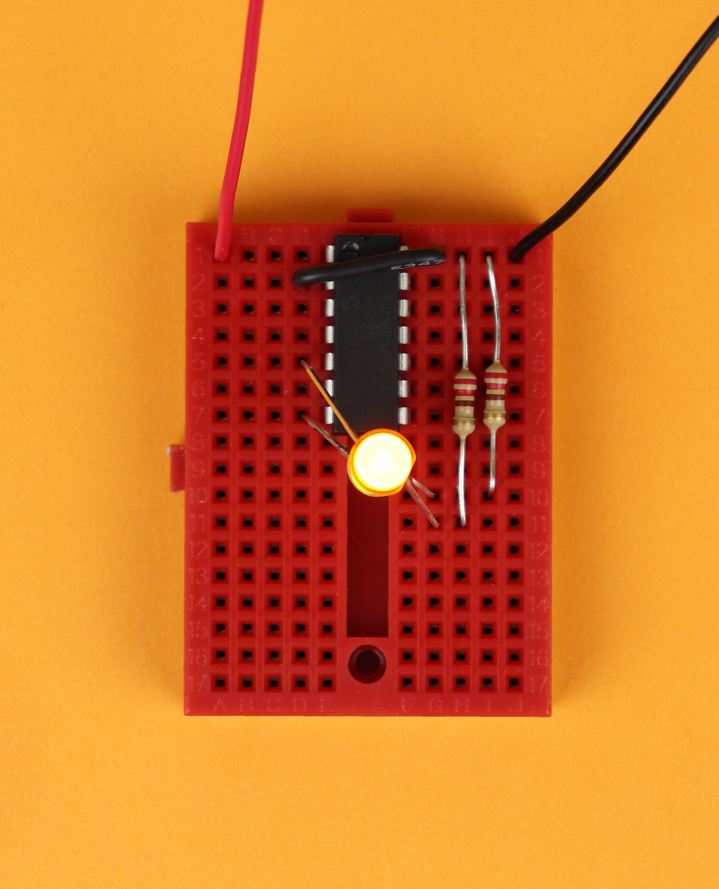
Here you can see the candle circuit from the side. I mounted the two LEDs on top of each other because it mimicks the two colors found in a flame quite well I think. But there are of course other ways to mount the LEDs as well.
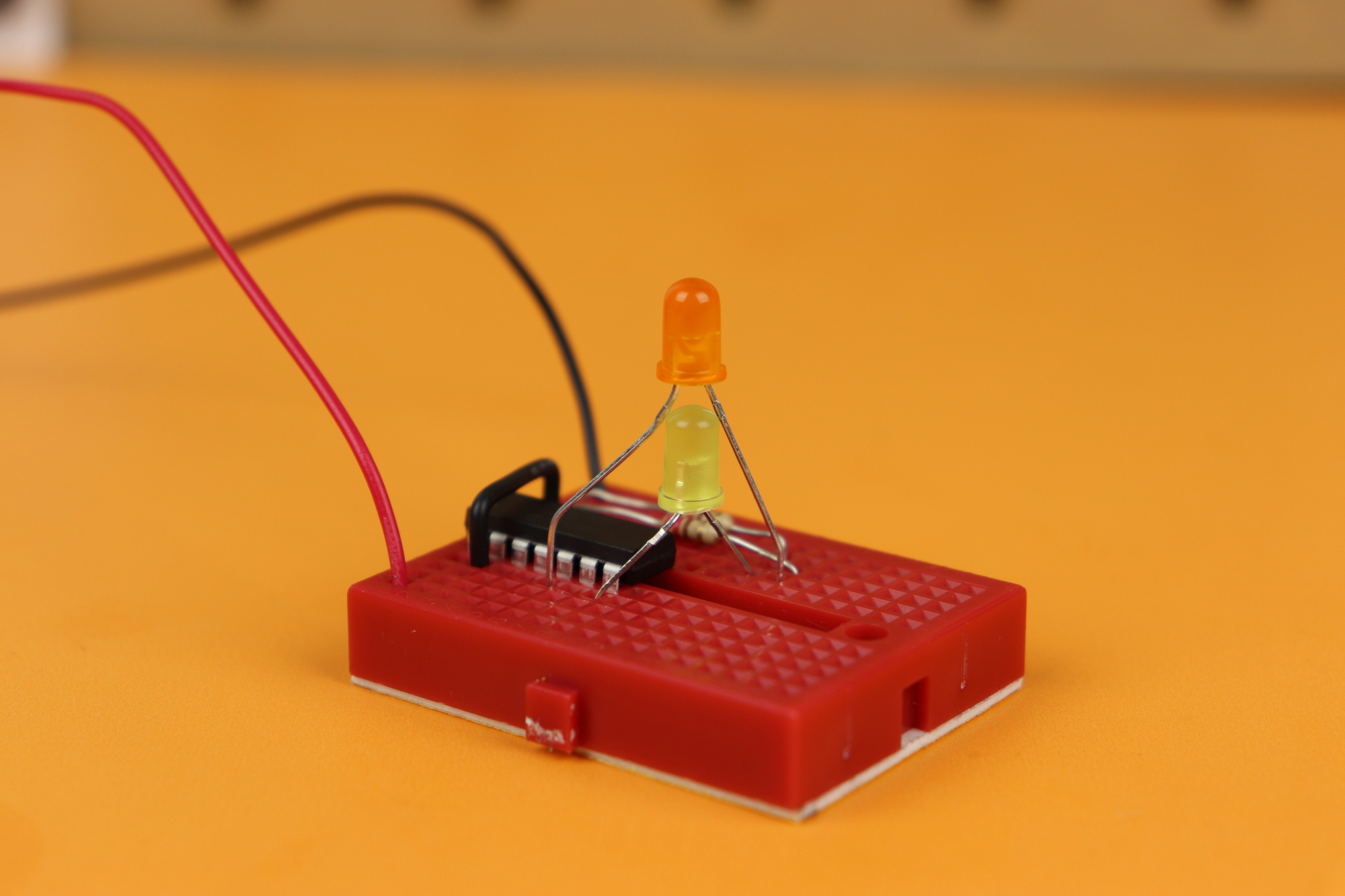
At first I thought I would place the LEDs inside a real candle, so that it looks like the candle is actually lit, but I decided against it because the LEDs I am using here are not bright enough. Our flickering LED candle is very versatile and can be used for many different applications, so maybe it's not that bad that we didn't end up gluing it into a candle :)
YouTube video
I covered this entire project in a dedicated YouTube video:
Final thoughts?
Congratulations, you did it, another successful project (I hope)! As you can see, sometimes microcontroller projects are a bit heavy on the software while the external circuitry is super simple.
I like this project because it teaches us how to use ADCs, PWMs, timers, interrupts, and we don't get lost in the complexity of the external circuitry. Now that we have mastered these concepts we can soon use them in more complicated projects. Think of the possibilities!
Please let me know if you have any questions, and I will do my best to get back to you. Thank you for your interest, for reading this article, and I will see you next time!
Appendix: The full source code
Here you can find the full source code. The code (as well as the .hex file) are also available for download in the resources box.
/*
 * File:   main.c
 * Author: boos
 *
 * Created on December 10, 2019, 12:23 PM
 */

// CONFIG1
#pragma config FOSC = INTOSC    // Oscillator Selection Bits (INTOSC oscillator: I/O function on CLKIN pin)
#pragma config WDTE = OFF       // Watchdog Timer Enable (WDT disabled)
#pragma config PWRTE = OFF      // Power-up Timer Enable (PWRT disabled)
#pragma config MCLRE = OFF      // MCLR Pin Function Select (MCLR/VPP pin function is digital input)
#pragma config CP = OFF         // Flash Program Memory Code Protection (Program memory code protection is disabled)
#pragma config BOREN = OFF      // Brown-out Reset Enable (Brown-out Reset disabled)
#pragma config CLKOUTEN = OFF   // Clock Out Enable (CLKOUT function is disabled. I/O or oscillator function on the CLKOUT pin)
#pragma config IESO = OFF       // Internal/External Switchover Mode (Internal/External Switchover Mode is disabled)
#pragma config FCMEN = OFF      // Fail-Safe Clock Monitor Enable (Fail-Safe Clock Monitor is disabled)

// CONFIG2
#pragma config WRT = OFF        // Flash Memory Self-Write Protection (Write protection off)
#pragma config CPUDIV = NOCLKDIV// CPU System Clock Selection Bit (NO CPU system divide)
#pragma config USBLSCLK = 48MHz // USB Low SPeed Clock Selection bit (System clock expects 48 MHz, FS/LS USB CLKENs divide-by is set to 8.)
#pragma config PLLMULT = 3x     // PLL Multipler Selection Bit (3x Output Frequency Selected)
#pragma config PLLEN = ENABLED  // PLL Enable Bit (3x or 4x PLL Enabled)
#pragma config STVREN = ON      // Stack Overflow/Underflow Reset Enable (Stack Overflow or Underflow will cause a Reset)
#pragma config BORV = LO        // Brown-out Reset Voltage Selection (Brown-out Reset Voltage (Vbor), low trip point selected.)
#pragma config LPBOR = OFF      // Low-Power Brown Out Reset (Low-Power BOR is disabled)
#pragma config LVP = ON         // Low-Voltage Programming Enable (Low-voltage programming enabled)

#include <xc.h>

// method prototypes
unsigned char getRandomNumber ();

// global variables
static unsigned int rnd = 0;
static unsigned char t = 0, newValue1 = 0, newValue2 = 0, maxValue = 0, mean_values = 0, speed1 = 0, speed2 = 0, fade_delay = 0;
static unsigned char random_number1 = 0, random_number2 = 0, mode = 0; // 3

// useful abbreviation
#define JP_fast (!RA5)

void main(void) {

    // set internal oscillator to 4MHz
    IRCF0 = 1;
    IRCF1 = 0;
    IRCF2 = 1;
    IRCF3 = 1;

    // weak pull-up for jumper
    TRISA5 = 1;
    WPUA5 = 1;
    nWPUEN = 0;

    // TIMER0 settings

	// internal clock, no prescaler, interrupt on overflow
	TMR0CS = 0;
	PSA = 1;
	TMR0IE = 1;

	// enable global interrupts
	GIE = 1;

    // ADC settings

	// ADC sampling frequency per bit is F_osc/2
	ADCS0 = 0;
	ADCS1 = 0;
    ADCS2 = 0;

    // result alignment
    ADFM = 1;

	// RA4, RC0, RC1, RC2 ports as analog inputs
	TRISA4 = 1;
    TRISC0 = 1;
    TRISC1 = 1;
    TRISC2 = 1;
    ANSA4 = 1;
    ANSC0 = 1;
    ANSC1 = 1;
    ANSC2 = 1;

	// turn the ADC on
	ADON = 1;

    // PWM settings

    // ports
    TRISC5 = 0;
    TRISC3 = 0;

    // configure TIMER2
    PR2 = 0xff;
    T2CON = 0b100;

    // turn on PWM modules
    PWM1EN = 1; PWM1OE = 1;
    PWM2EN = 1; PWM2OE = 1;

    // main loop
    while (1) {

        // enable fast mode if the jumper
        // is connected to ground
        if (JP_fast) {
            mode = 0;
        } else {
            mode = 1;
        }

		// fast or slow?
		if (mode == 0) {
			maxValue = 200;  mean_values = 1;   fade_delay = 0;
		} else if (mode == 1) {
			maxValue = 250;  mean_values = 16;  fade_delay = 4;
		}

		// the actual animation
		if (newValue1 >= maxValue) {
			rnd = 0;
			for (t = 0; t < mean_values; t++) {
				rnd += getRandomNumber();
			}
			random_number1 = rnd / t;
			newValue1 = 0;
		}
		if (newValue2 >= maxValue) {
			rnd = 0;
			for (t = 0; t < mean_values; t++) {
				rnd += getRandomNumber();
			}
			random_number2 = rnd / t;
			newValue2 = 0;
		}

    }

    return;

}

// the interrupt service routine
void __interrupt () isr (void) {

	if (TMR0IF) {

        // animation
		newValue1++;
        newValue2++;
		speed1++;
        speed2++;
		if (speed1 >= fade_delay) {
			if (PWM1DCH > random_number1) {
				PWM1DCH--;
			} else if (PWM1DCH < random_number1) {
				PWM1DCH++;
			}
			speed1 = 0;
		}
		if (speed2 >= fade_delay) {
            if (PWM2DCH > random_number2) {
				PWM2DCH--;
			} else if (PWM2DCH < random_number2) {
				PWM2DCH++;
			}
            speed2 = 0;
        }

		// reset interrupt flag
		TMR0IF = 0;

	}

}

// this method creates a random number between 0 and 240
unsigned char getRandomNumber () {

	unsigned char tmp = 0;

    // read channel AN3
    CHS0 = 1; CHS1 = 1; CHS2 = 0; GO = 1; while (GO);
	tmp = ADRESL & 1;

    // read channel AN4
    CHS0 = 0; CHS1 = 0; CHS2 = 1; GO = 1; while (GO);
	tmp += (ADRESL & 1) << 1;

    // read channel AN5
    CHS0 = 1; CHS1 = 0; CHS2 = 1; GO = 1; while (GO);
	tmp += (ADRESL & 1) << 2;

    // read channel AN6
    CHS0 = 0; CHS1 = 1; CHS2 = 1; GO = 1; while (GO);
	tmp += (ADRESL & 1) << 3;

    // multiply result by 16 to create a random number between 16 and 255
	return (tmp << 4);

}


