How to build a better binary clock
November 18, 2023 • project
We do a lot of tutorials here, but in this project we stop and put it all together by building a special type of clock: a binary clock. It uses WS2812 NeoPixel LEDs to display the time, a rotary encoder to adjust it, and the DS1302 real-time clock IC to keep the time, even if the power cuts out. So let's get started and build this thing!
What is a binary clock?
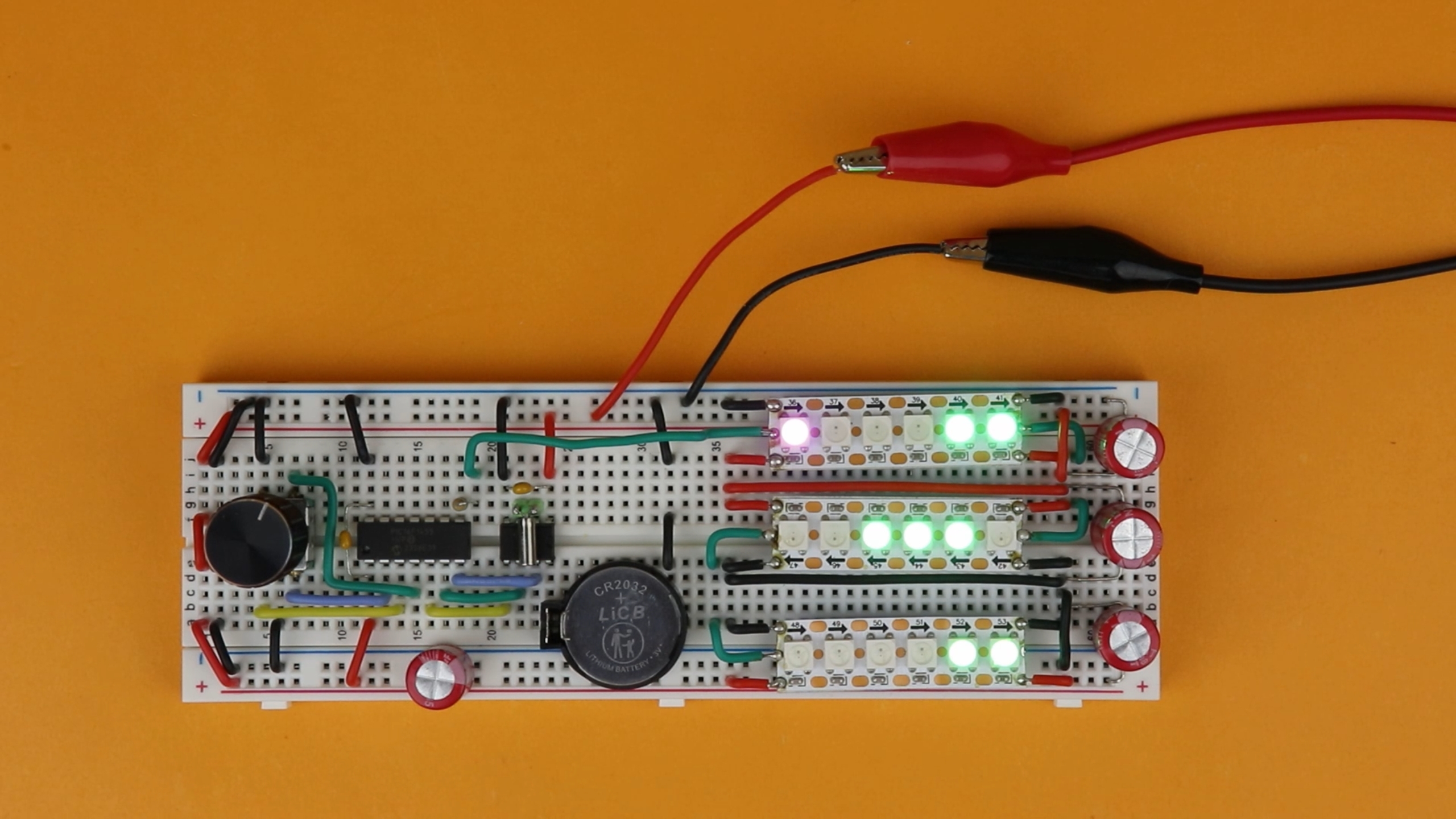
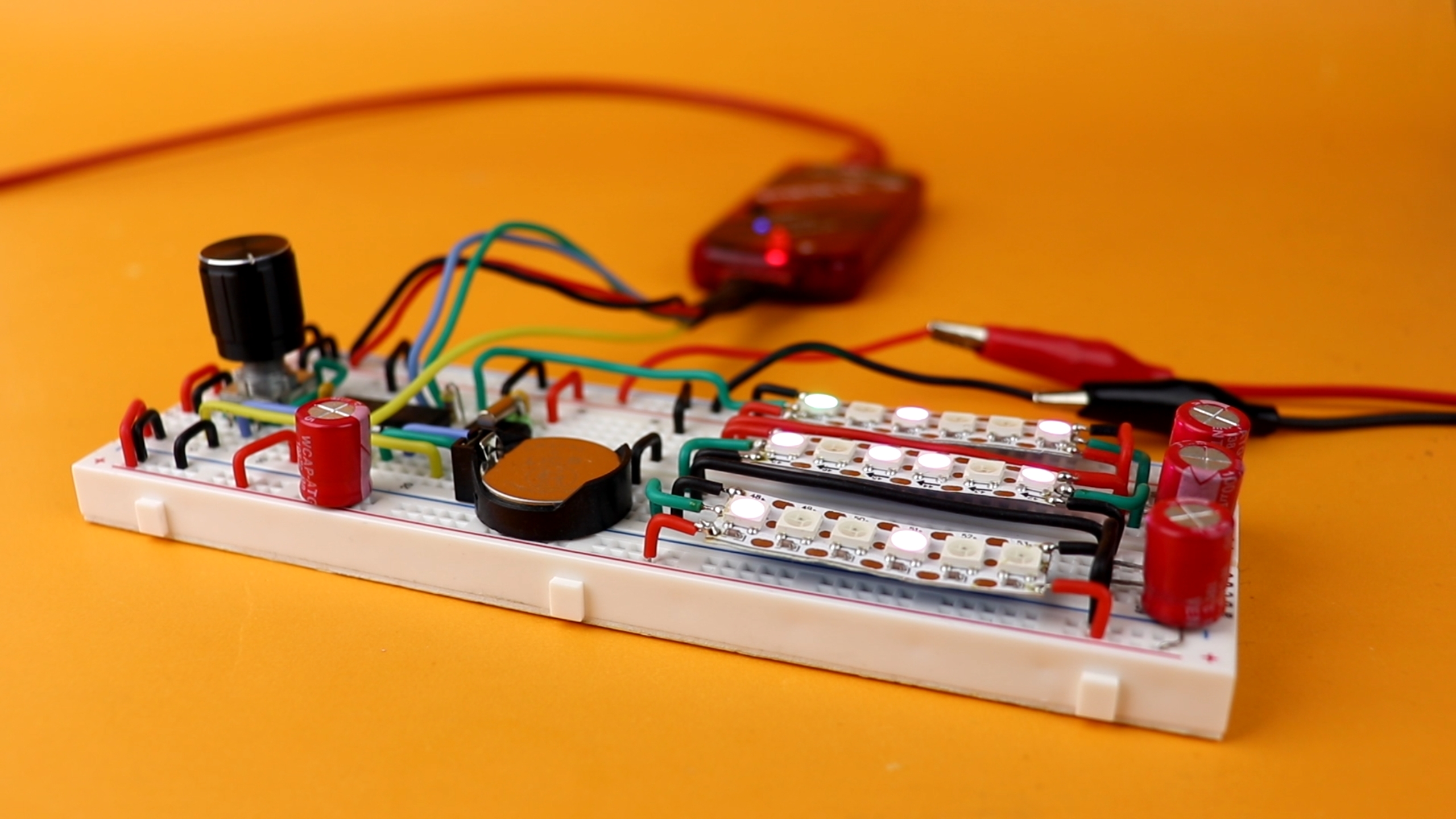
But before we geht ahead of ourselves, what is a binary clock? I think the best way to understand it is with a picture:
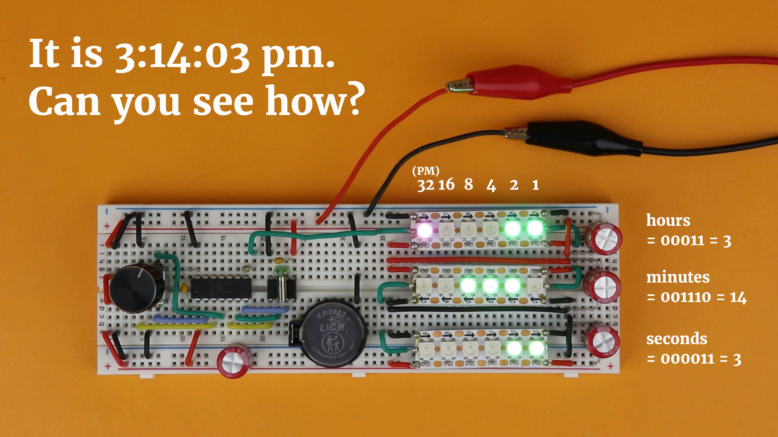
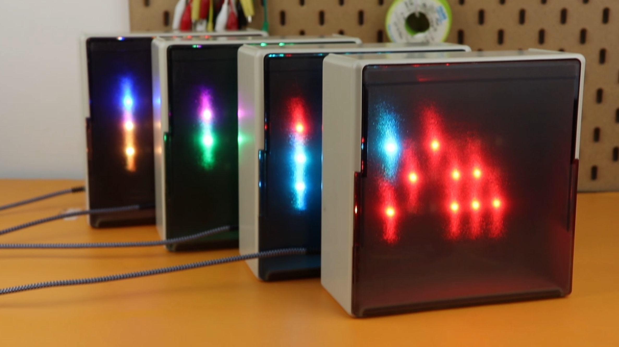
There are three rows of six LEDs each. The upper row is for the hours, the middle row is for the minutes, and the bottom row is for the seconds.
The column of each LED determines its value. The rightmost LED in each row is 1, and as we move to the left, the value multiplies by a factor of 2. This means that the LEDs stand for 1, 2, 4, 8, 16, and 32, moving from right to left. (In the first row, the leftmost LED is not 32, but it works as a PM indicator.)
To tell the time, we have to add all the LED values in each row. For the hours it means that it is 1+2 = 3 o'clock. For the minutes it means 2+4+8 = 14 minutes. And for the seconds, its's again 1+2 = 3 seconds. The purple LED does not count towards the hours, it just means that it is 3pm and not 3am.
It takes some practice to read it fast enough, especially with the seconds blinking on and off more quickly, but I think it's a very unique look that can also be a lot of fun.
And before we will get started with building the clock, I wanted to highlight its features:
- Backup battery: The DS1302 real-time clock IC, together with a coin cell backup battery, save the time during power outages. I always find this very convenient.
- Adjustable LED colors: Since we are using the WS2812 NeoPixel LED strip, we can adjust the LED colors to anything we like, which makes this whole setup super flexible.
- Easy to adjust: we can set the time and change the colors with a rotary encoder, which I find a lot more convenient and user-friendly compared to pushbuttons.
So, as you can see, we are using three techniques that we already covered in past tutorials. Why nothing new today? I find it important to stop sometimes and pause, and to realize what we have already learned. This is one of those projects. If you have followed our journey until today, you too can build this easily, and I hope it will inspire you to keep learning more about electronics and microcontrollers :)
What you need
Here is a quick overview of what you need if you want to build this project:
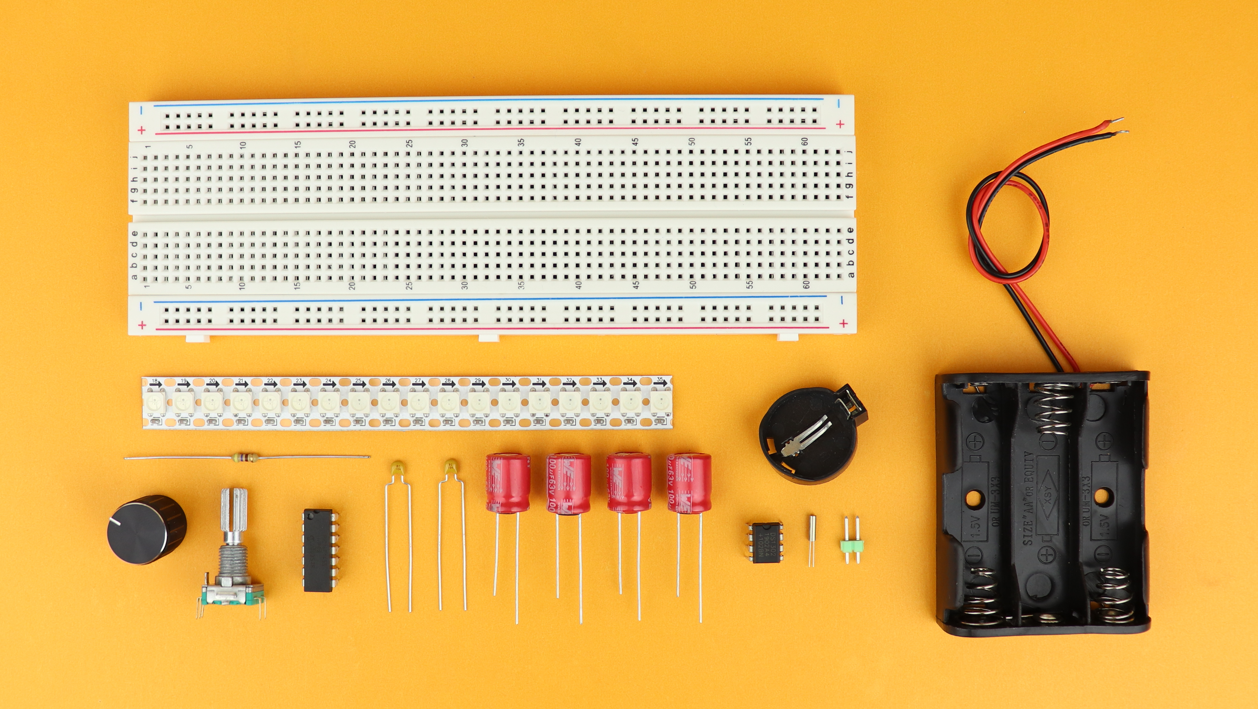
As always, all components are listed in the components box of this article, but let's go through the major components together.
- The PIC16F1455 microcontroller is the brain of the clock.
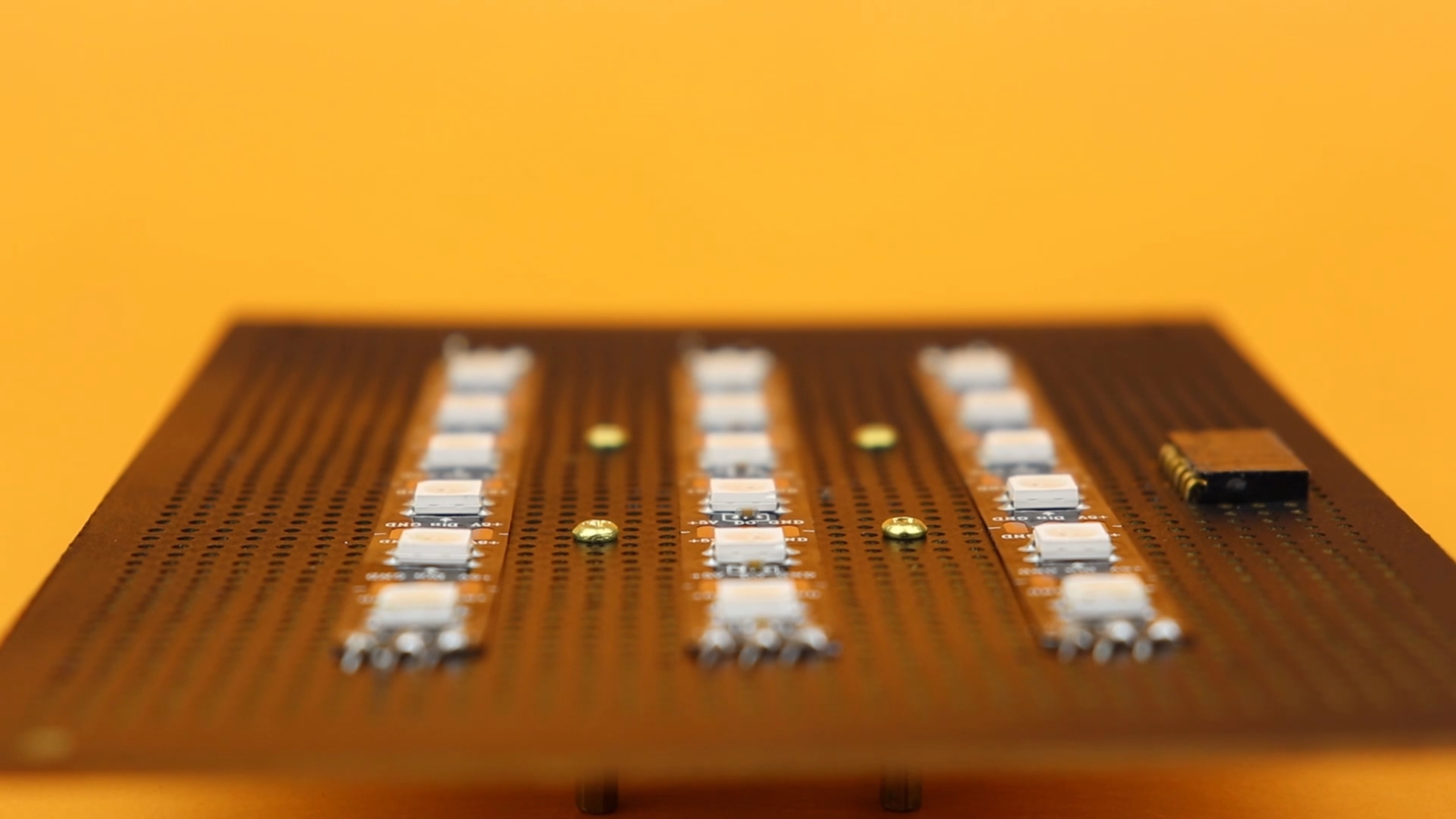
- The time is shown using 18 LEDs of a WS2812 “NeoPixel” LED strip.
- A rotary encoder is used to set the time and adjust the LED brightness and color.
- A backup battery in combination with the DS1302 real-time clock IC make sure that the clock keeps the time even if the main power cuts out. The chip uses a 32.768kHz watch crystal to keep the time, and because this is hard to mount on a breadboard because it's so tiny, I recommend to solder it to a pinheader. (If you cannot solder, then you can get a ready-made DS1302 module instead.)
- A bunch of capacitors and a resistor to stabilize things (see more below).
Now that we know what we need, let's figure out how to connect it all, and let's have a look at the schematic!
Schematic
Here it is, in all its glory:
As always, don't be discouraged by it, let's break it down into smaller pieces.
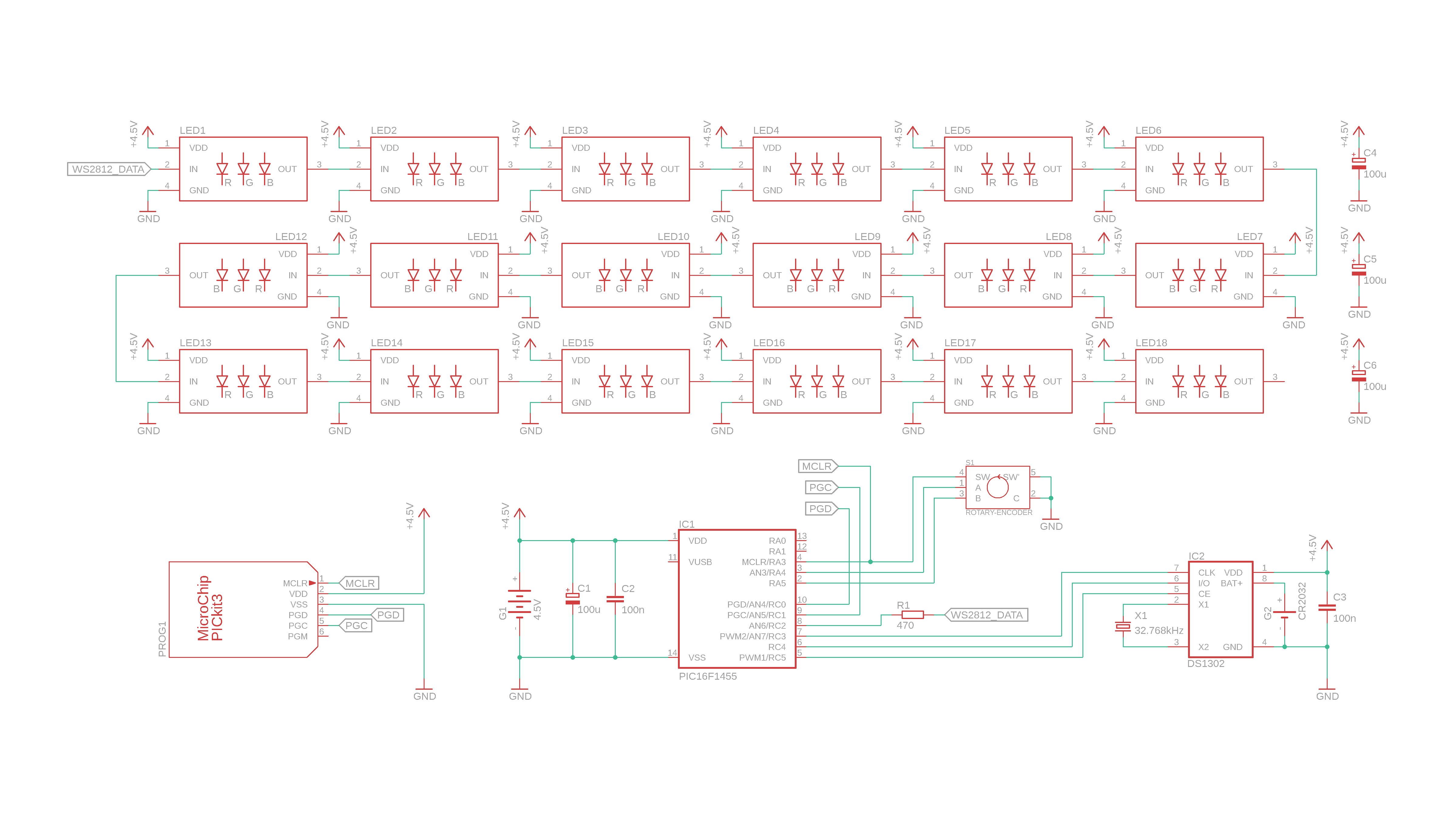
- The brains of the operation is the PIC16F1455 microcontroller, and the capacitors C1 and C2 next to it are there for stability.
- Three of the PIC16F1455's inputs are connected to the rotary encoder: two of them detect the direction in which it is turned, and another one is connected to the rotary encoder's internal pushbutton.
- And our real time clock IC, the DS1302, which has three wires shared with the PIC: clock, data, and enable. The watch crystal X1 is directly connected to the DS1302, so that it can generate a stable 1Hz clock signal, independent of the PIC controller, and for that reason it has its own 3V backup battery directly connected to it as well. And for stability it also gets its own 100 nanofarad bypass capacitor C3.
- The huge chunk at the top are our WS2812 NeoPixel LEDs. Sorry for the scary drawing. But most of this is pretty straightforward, because its just individual WS2812 NeoPixel LEDs all wired in series, and if you use an LED strip, you won't have to do all that wiring yourself.
- There are a few details about the LEDs that I wanted to mention. First off, the 470 Ohms resistor R1 is there to protect our PIC. The PIC sends out the LED data from pin RC2. Usually, the input pins of the WS2812 LEDs are high impedance, but when all LEDs are turned ON, the circuit draws a lot of power, which can make the supply voltage go down in some places of the circuit. If that happens, a small current can flow INTO the PIC, and this resistor basically limits that current to a non-lethal amount. If you have a good power supply, you don't necessarily need this, but hey, it's a cheap component that may save a more expensive one, so: why not.
- The last detail I wanted to mention are the capacitors, C4, C5, and C6. They are kind of big with 100μF, and I drew them close to each of the LED strip segments. We only use 18 LEDs, but keep in mind that each of these LEDs actually has 3 internal LEDs. So, it's actually 54 LEDs in total, and they can draw up to 20 milliamps each at full brightness. So we are talking about a maximum current of 1 amp, which is definitely noticeable, and can put a lot of strain on your power supply. And especially on a breadboard it is really important to ease that strain as much as possible, and these capacitors work do exactly that: they work as little buffers. This way, when a lot of LEDs are turned ON, the power supply has a bit more time to deliver the extra power. We will talk a bit more about this later.
- And the PICkit3 at the bottom left is there to send the program from our computer to the PIC16F1455 microcontroller. We only need it one time, to program the PIC, and it can be removed afterwards.
I hope this all makes sense, but if you have questions remember that there is also a YouTube video covering this project, and you can always reach out to me on social media. Alright, with the schematic out of the way, let's go ahead and put some components on our breadboard!
Building the circuit
And with that out of the way, let's build this circuit on a breadboard!
-
-
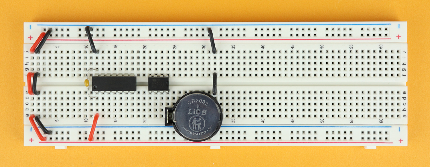
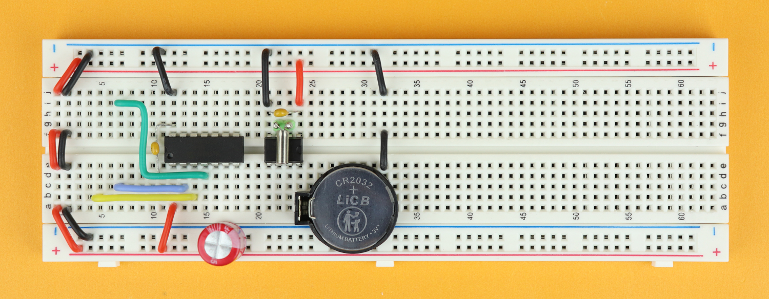
Step 1
Place the breadboard in front of you, with row 1 facing to the left.
-
-
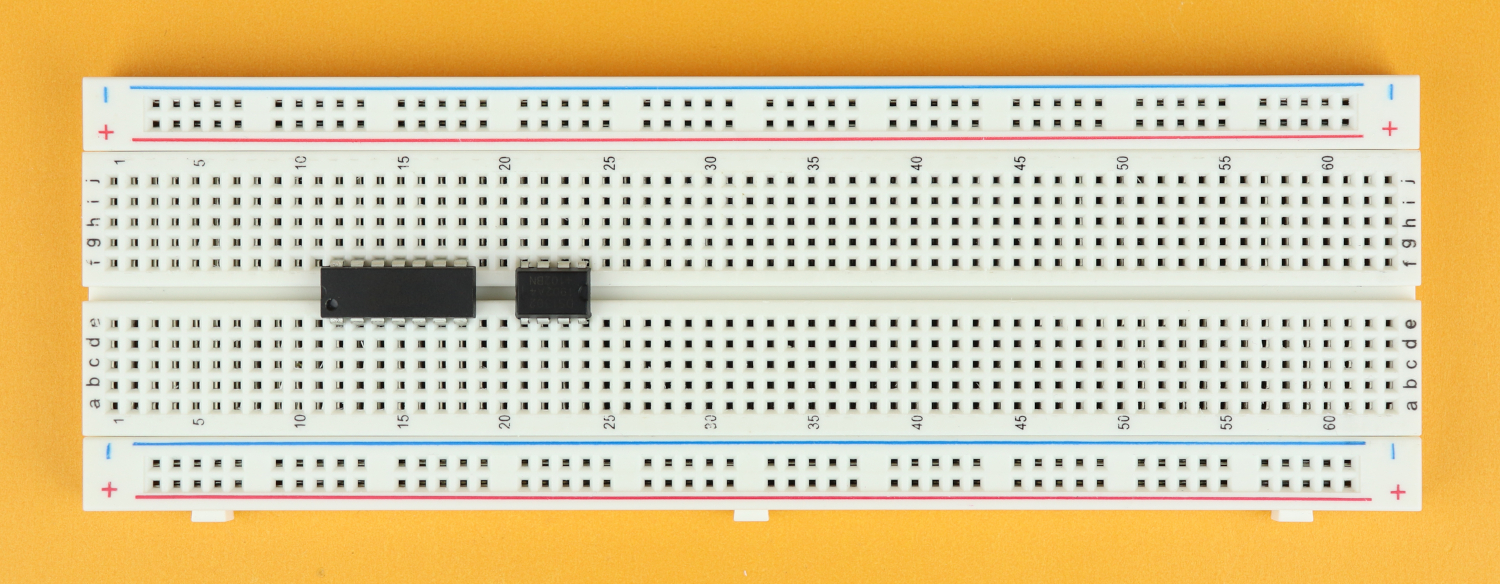
Step 2
Insert the PIC16F1455 in row 12 with its notch facing to the left, and then insert the DS1302 in row 21, with its notch facing to the right.
-
-
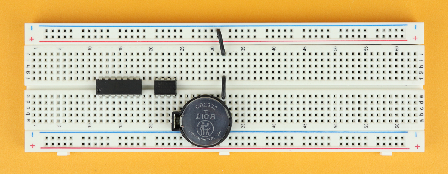
Step 3
Insert the DS1302's backup battery with its positive terminal in row 24, so that its negative terminal ends up in row 32. Connect it up to the ground rail with two additional black wires as shown.
-
-
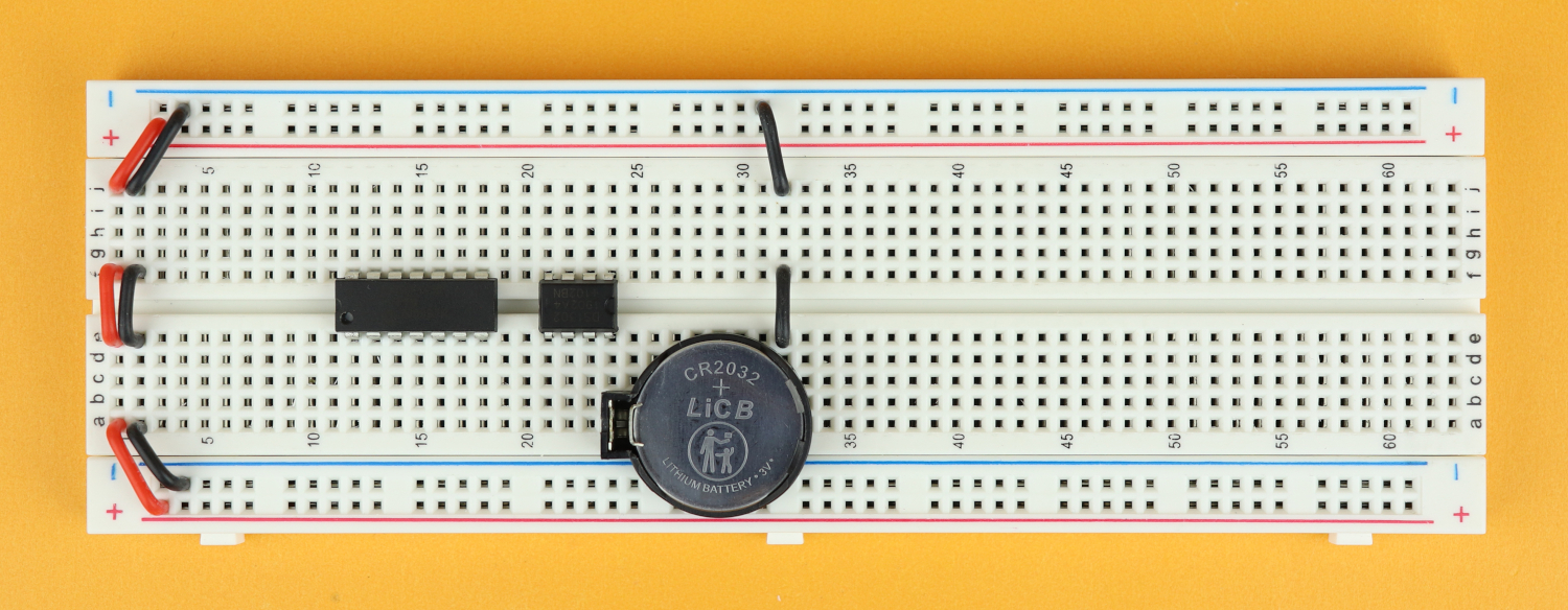
Step 4
Connect the power rails on both sides of the breadboard in rows 1 and 2 using red wires for VDD and black wires for GND.
-
-
Step 5
Connect power to the PIC16F1455: pin 1 is VDD, and pin 14 is ground. Also add the 100nF bypass capacitor C2 close to the chip between pins 1 and 14 (polarity doesn't matter, you can plug it in either way).
-
-
Step 6
Place the chunky 100 microfarad bulk capacitor C1 in the power rail close to the PIC16F1455, and make sure its negative terminal is really in the ground rail.
-
-
Step 7
For the DS1302, VDD goes to pin 1, and ground goes to pin 4.
-

-
Step 8
Add the 32.768kHz watch crystal between pins 2 and 3.
-
-
Step 9
Insert the 100nF bypass capacitor C3 between pins 1 and 4.
-
-
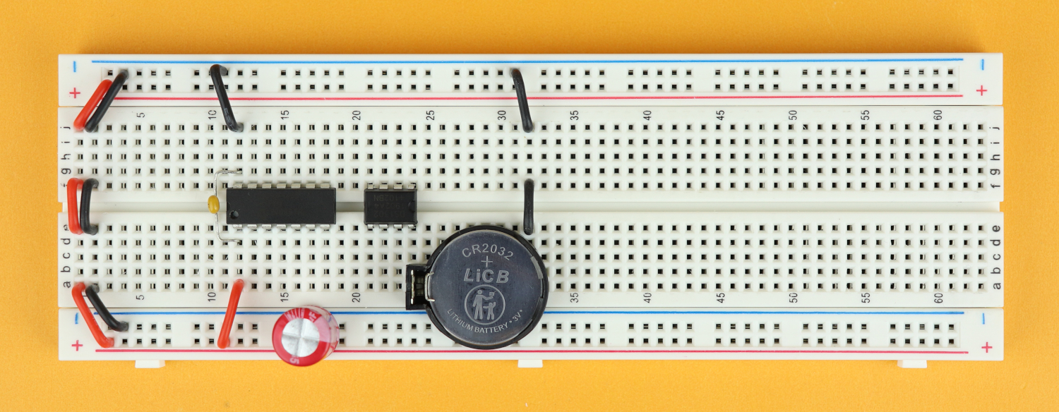
Step 10
Connect our (for now not visible) rotary encoder. Pin A goes from row 5 to pin 3 of the PIC, pin B from row 7 to pin 2, and, on the other side, the pushbutton terminal goes from row 7 to pin 4 as shown in the picture.
-
-
Step 11
Pin C of the rotary encoder is ground and goes into the ground rail with a black wire, and so does the other side of the pushbutton. I know this looks weird right now, but we will place the rotary encoder in there shortly and it will all make sense.
-

-
Step 12
To connect the DS1302 to the PIC, we need to connect pin 5 to 5, pin 6 to 6, and pin 7 to 7. And keep in mind that these two chips are back to back when you make those connections.
-
-
Step 13
To get ready for our LEDs, place the 470 Ohms resistor at pin 8 of the PIC.
-
-
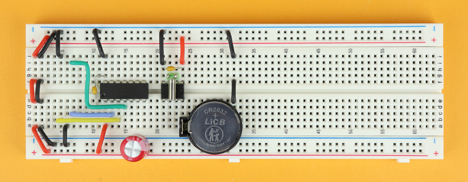
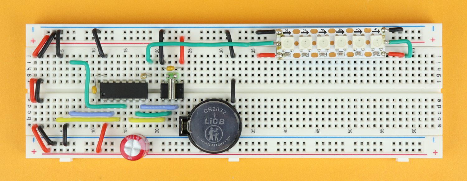
Step 14
Then, plug in the first LED strip module as shown. I cut the green data wire to the correct length so that it plugs directly into the data signal after the resistor.
-
-
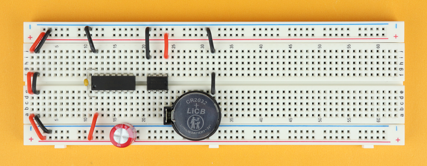
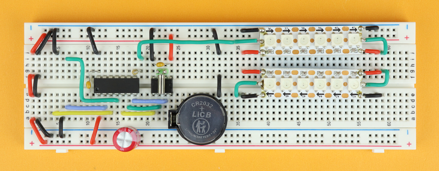
Step 15
Then, place the second WS2812 LED module...
-
-
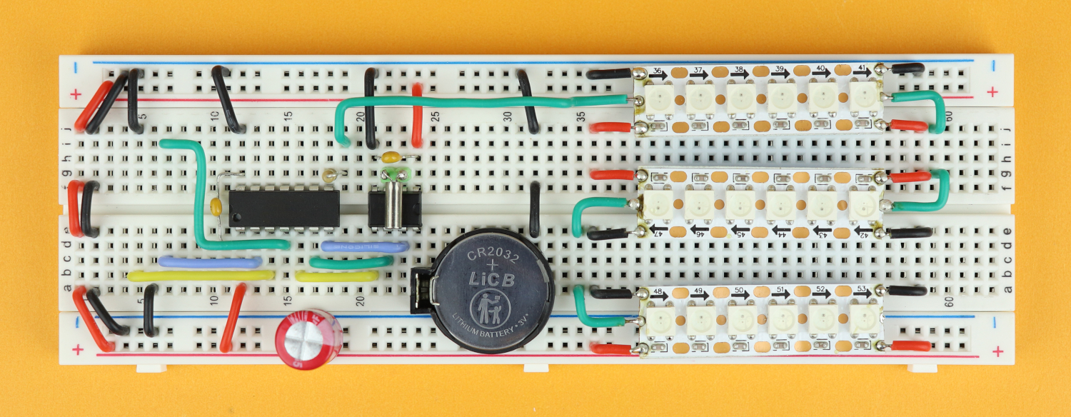
Step 16
...and then the third one, as shown. Again I made sure that the green data wires line up so that the data is really passed along the three LED strip segments.
-
-
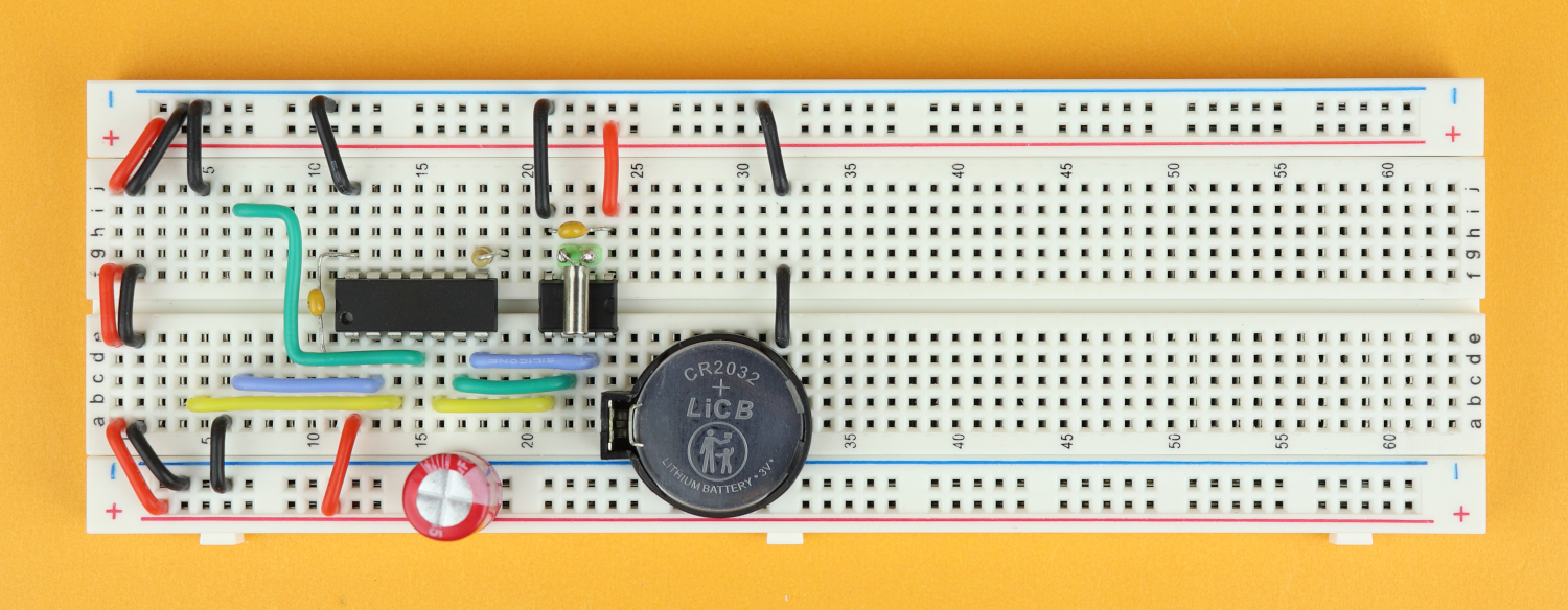
Step 17
Now we need to make sure the LED strips get power. First, connect VDD in row 58 to the upper positive power rail, and then ground in row 58 to the lower part of the negative power rail.
-
-
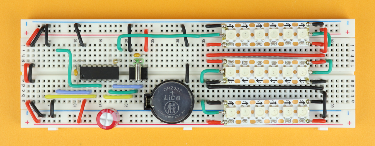
Step 18
For better conductivity I recommend to also add an extra VDD and GND line for the middle module.
-
-
Step 19
And, finally, for stability, each LED strip gets its own 100uF capacitor. Make sure that the negative terminal of the capacitors matches that of the LED strips.
-
-
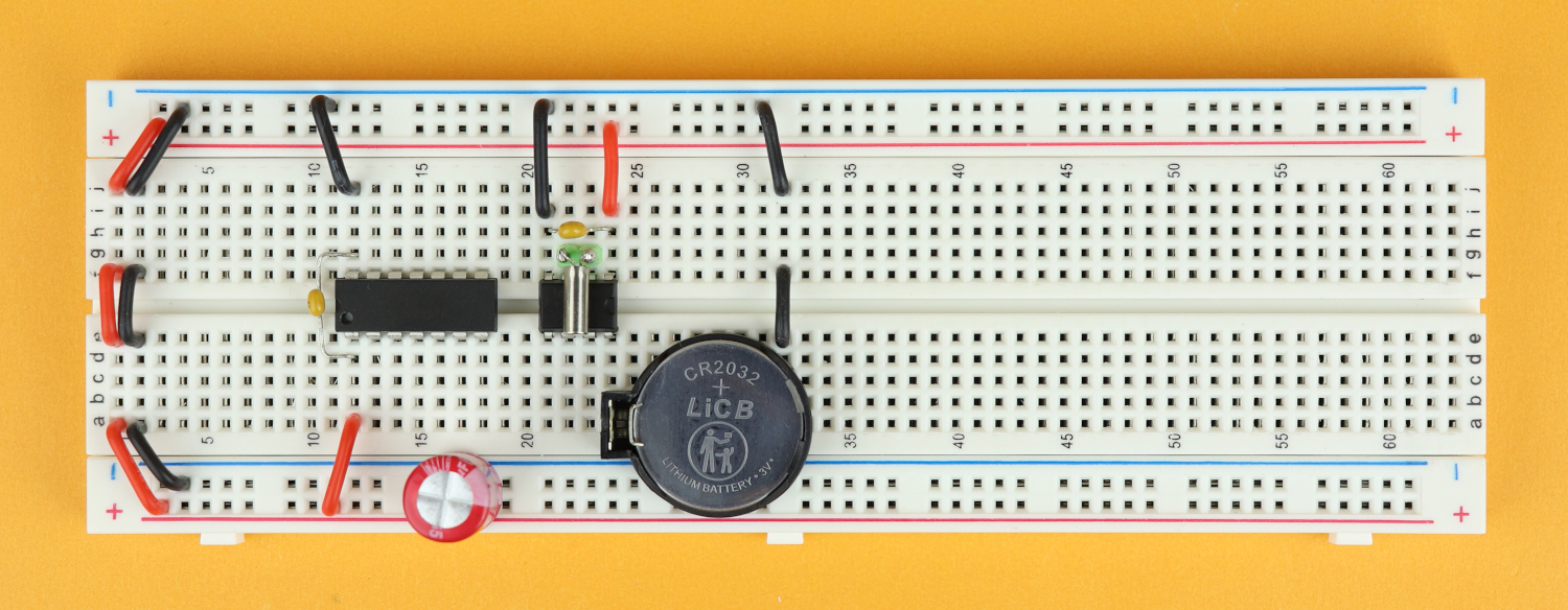
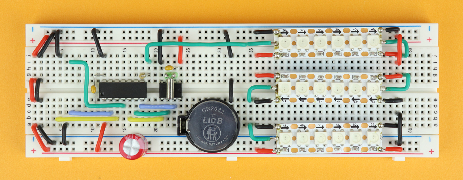
Step 20
Now we can plug in the rotary encoder in row 5.
-
-
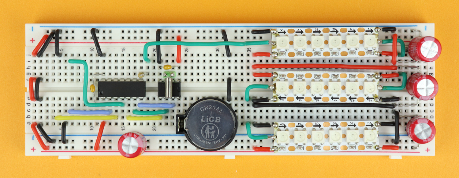
Step 21
And last, we have to connect the PICkit3 to the PIC16F1455 so that we can program it from our computer, and this is how it looks like: VDD and VSS go into the power rail, program data goes to pin 10 of the PIC, program clock to pin 9, and master clear to pin 4.
-
-
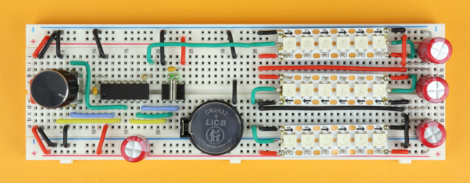
Step 22
And don't forget to connect our batteries as well, you can plug them straight into the power rail. Make sure that the power cables have a good connection to the power rail, this is important.
Programming the clock
So we're done with building the clock, but of course nothing happens yet when we power it on, because we need to program the microcontroller first. And for that we need three things:
- The MPLAB X IDE, to write our program.
- The XC8 compiler to turn our program into something that the microcontroller understands, and that is usually a .hex-file.
- And third, we need the MPLAB IPE to send that .hex-file onto the controller, and for that we also need the PICkit3.
Now, don't be scared, I know it sounds a bit complicated, but I have a very detailed article and video for you right here if you want to learn how to set it all up yourself in less than 10 minutes :)
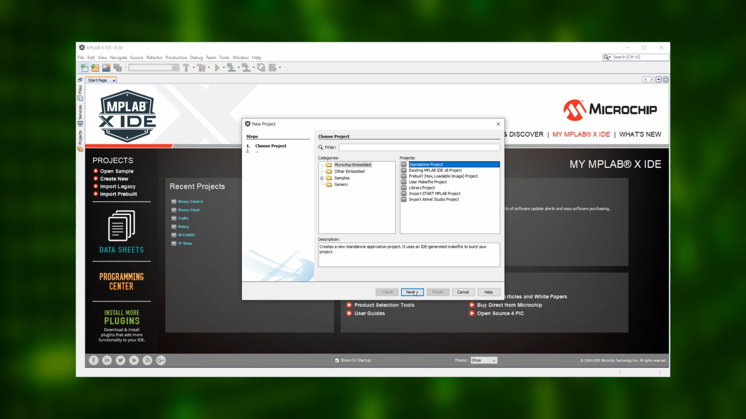
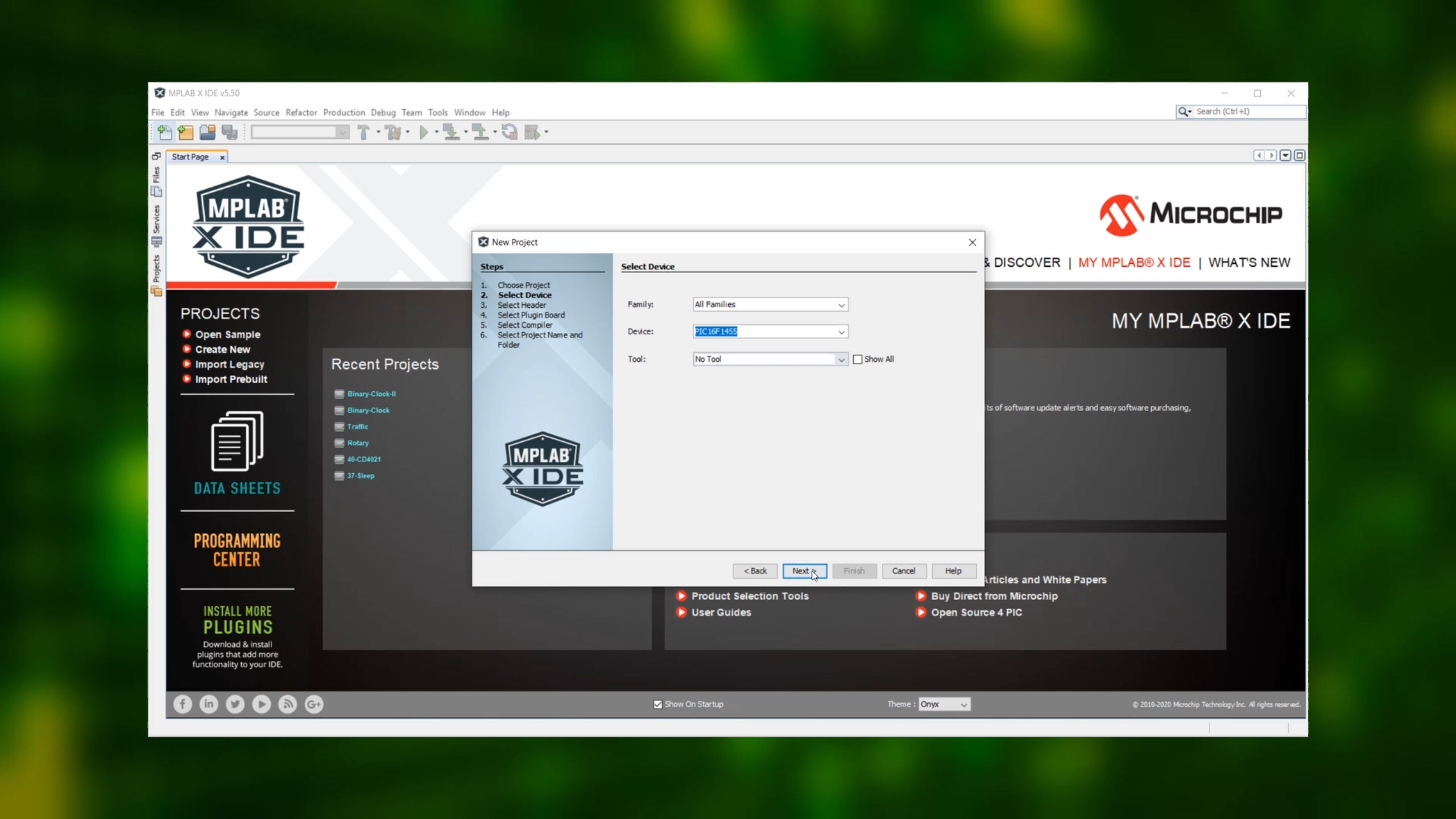
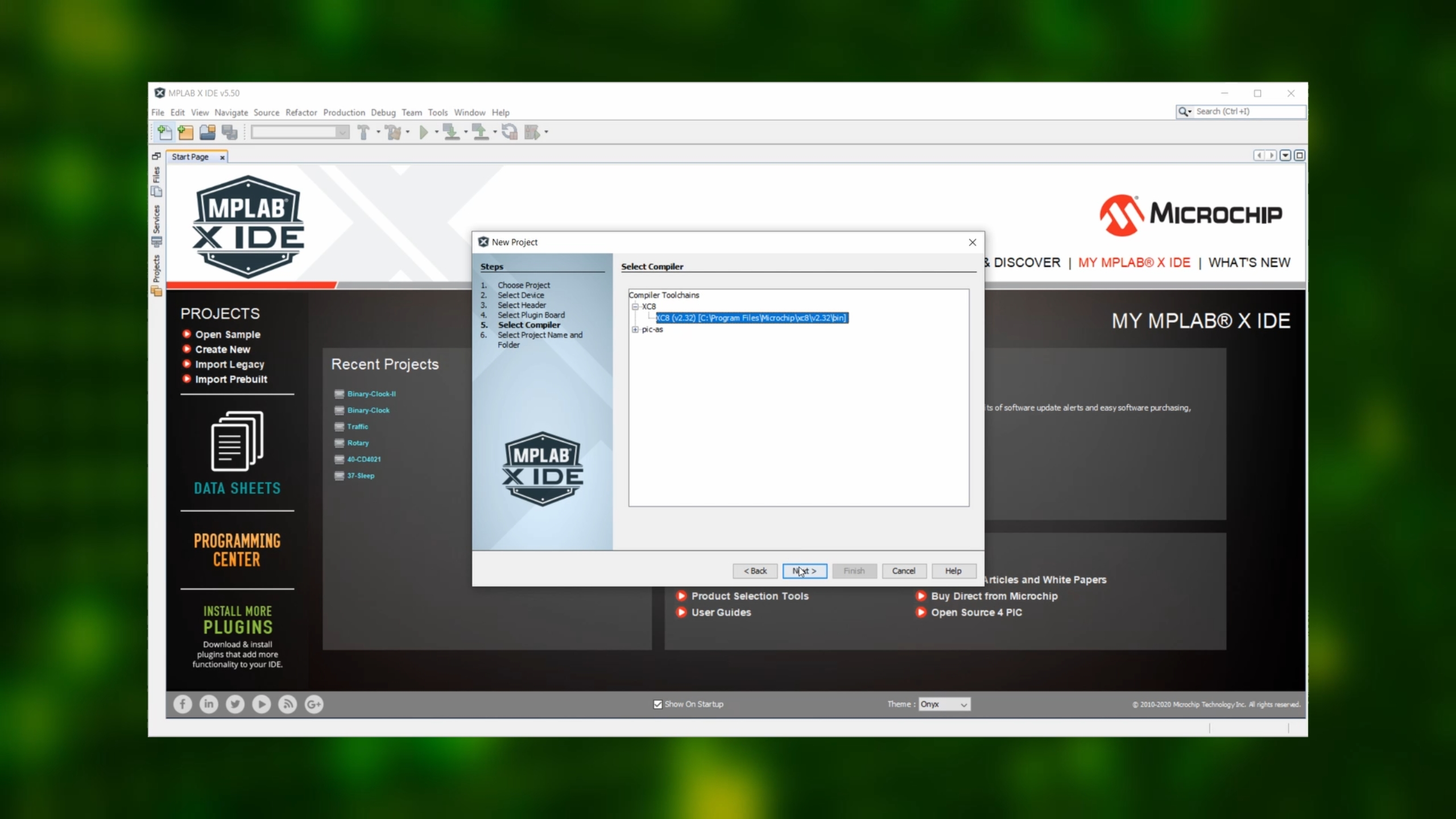
First, start the MPLAB IDE and create a new standalone project for the PIC16F1455 microcontroller.
We won't go into debugging here, so skip the next step.
Select the XC8 compiler and click on Next.
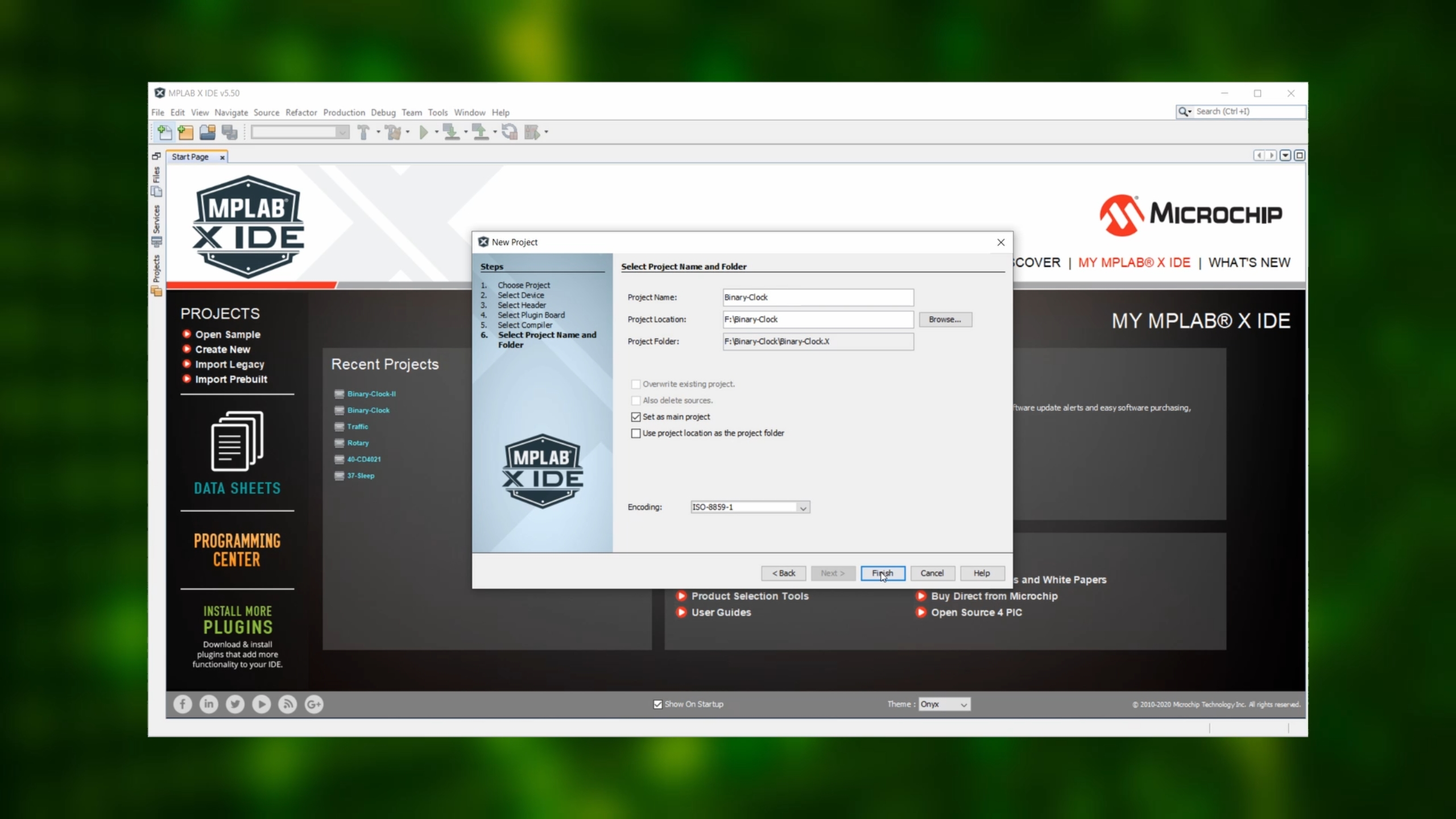
Then finish up the setup by selecting the folder where you want to store your project.
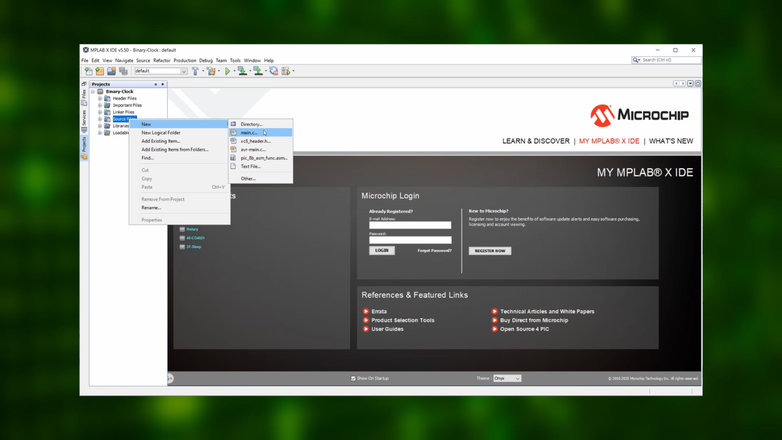
Next, let's add an empty main.c file to our project. This is where our program will go.
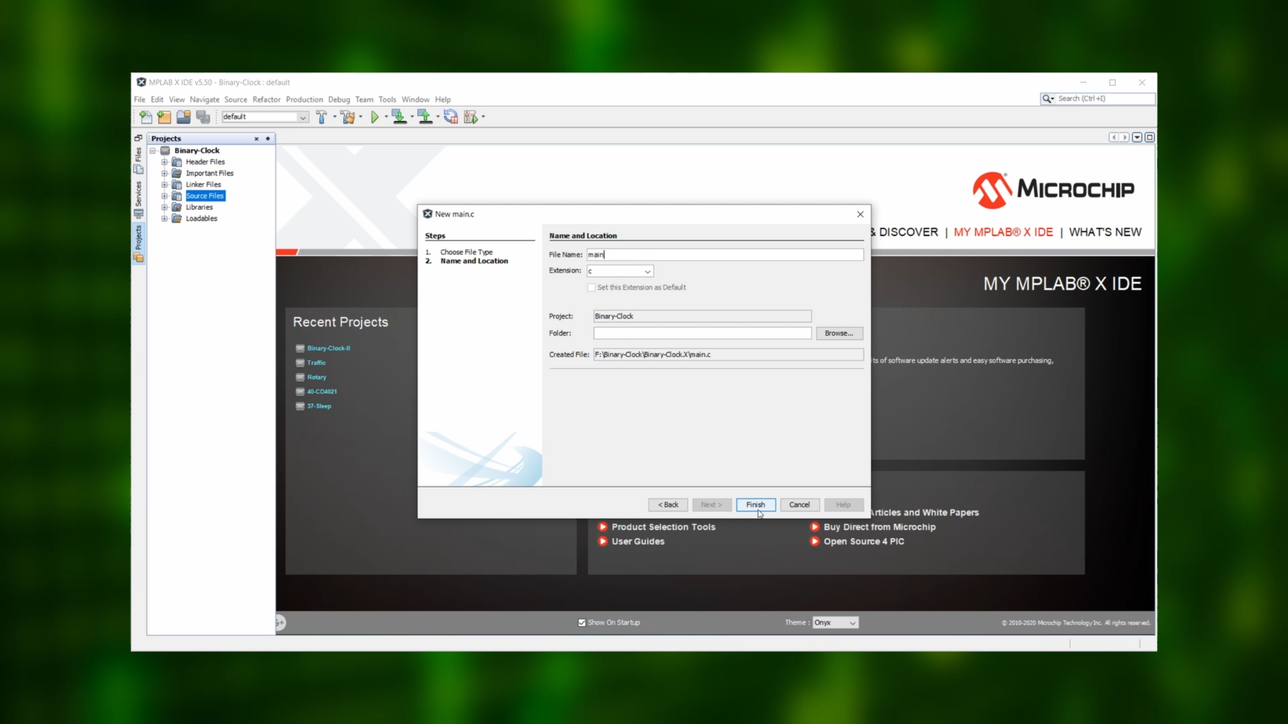
Set the filename to “main” like this:
Copy the source code at the bottom of the page. Back in the MPLAB IDE, delete everything in the main.c file and then paste the source code.
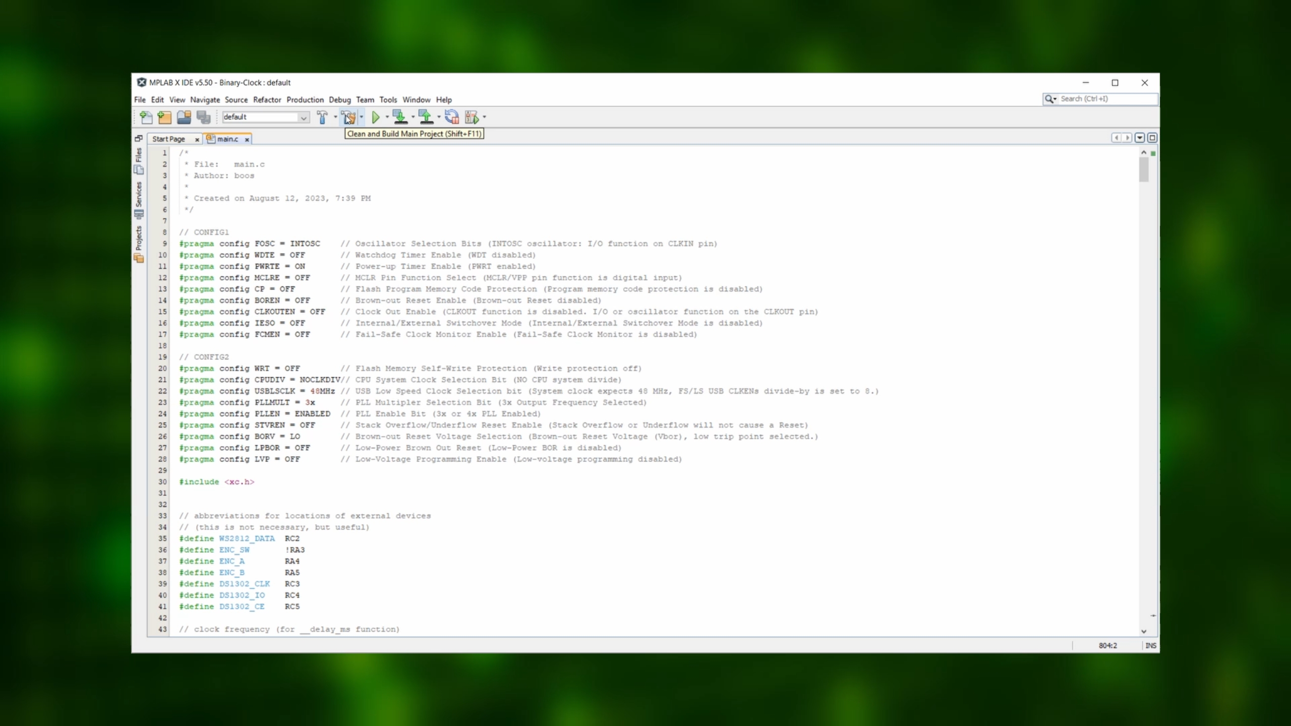
After that, up in the tool bar, click on the compile symbol.
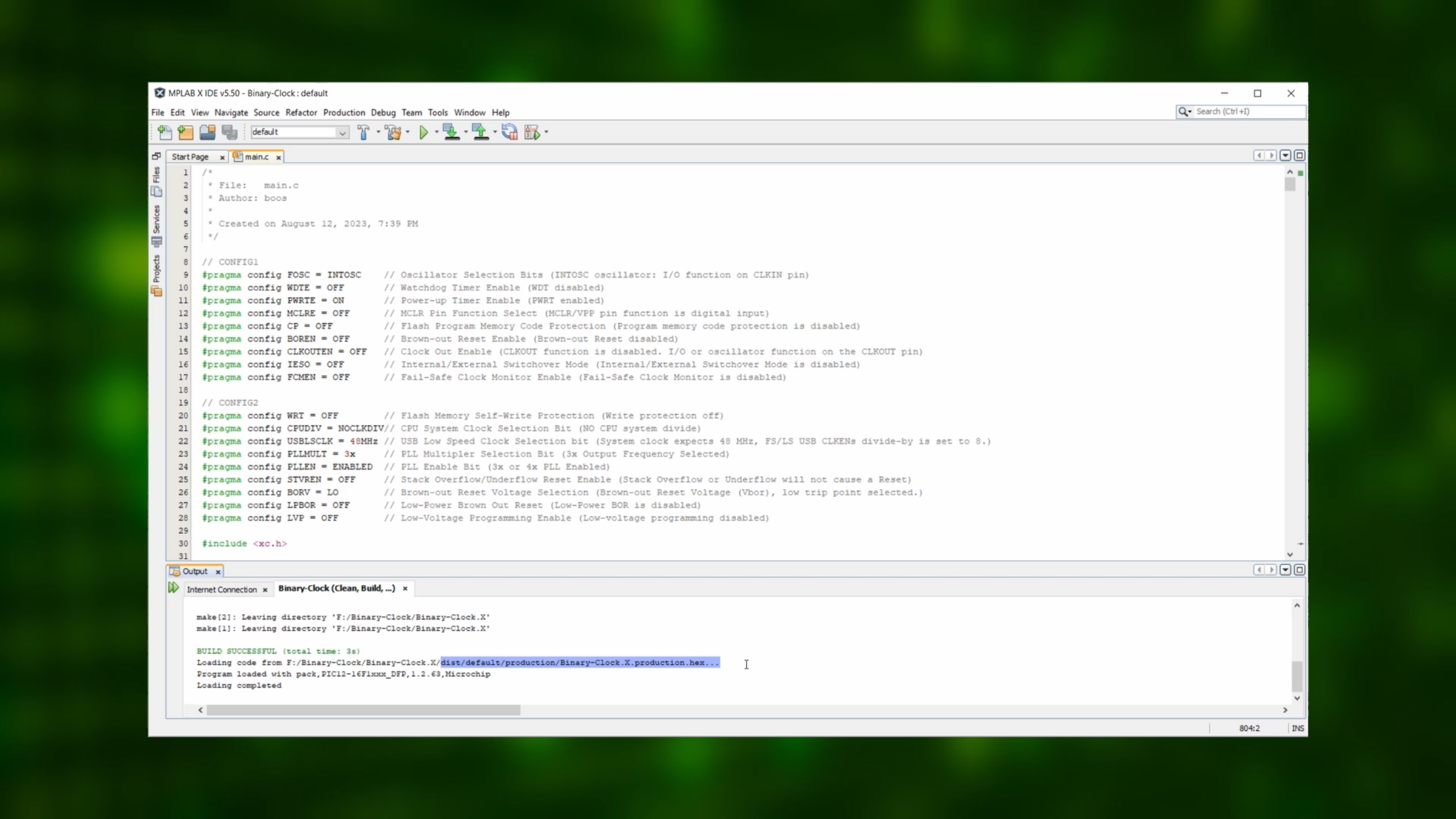
And after a few seconds and a successful build, the compiler tells us where we can find the .hex-file we just created. It is in the “dist/default/production” folder of our project:
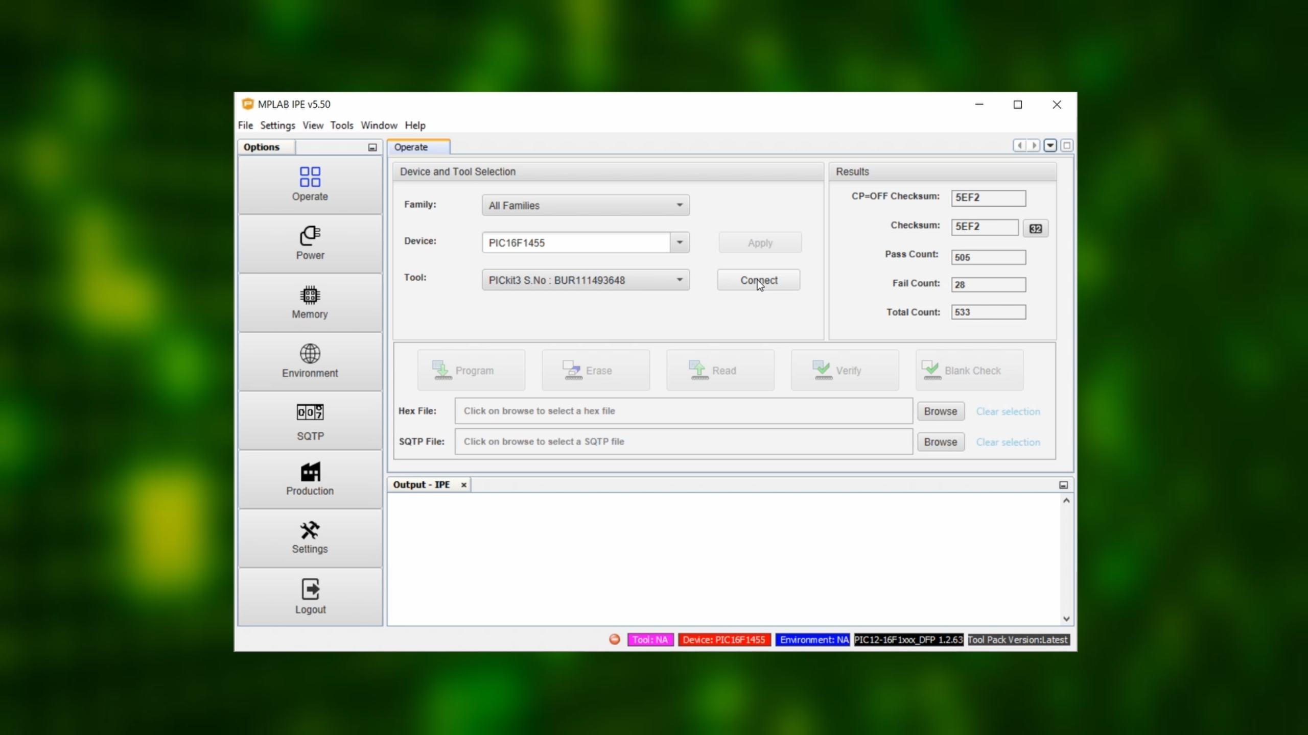
Now, start the MPLAB IPE, and select the PIC16F1455 as our device...
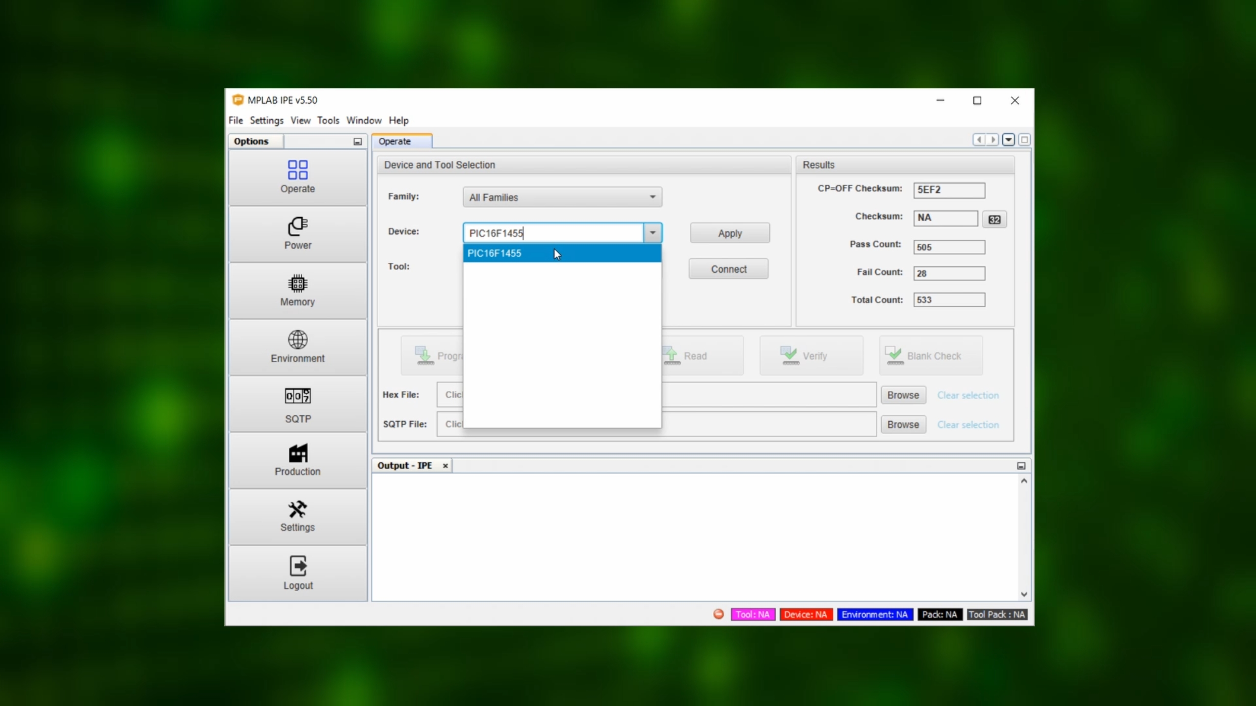
...and the PICkit3 as our tool in the settings, and click on connect:
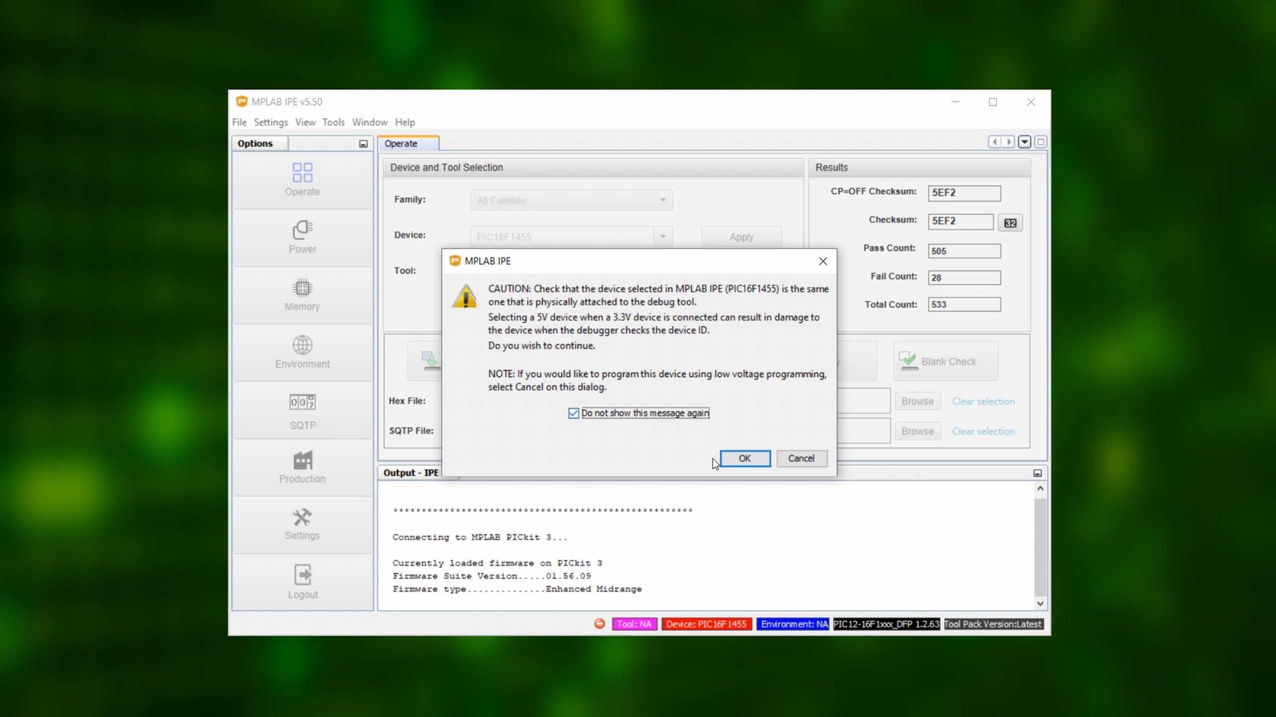
We can click OK on this dialog here:
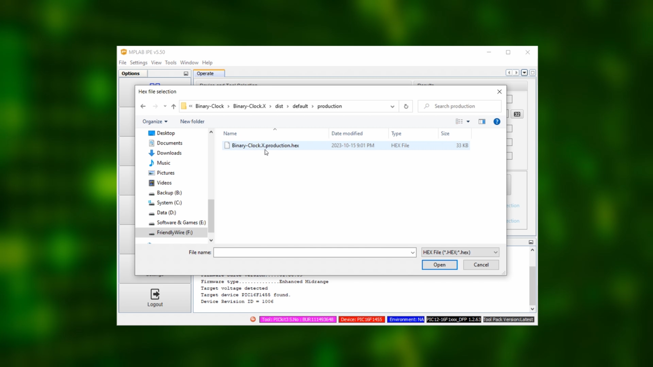
And then, after a few seconds, the PIC16F1455 should be detected. In the hex-file line click on Browse...

...and open the .hex-file we just created.
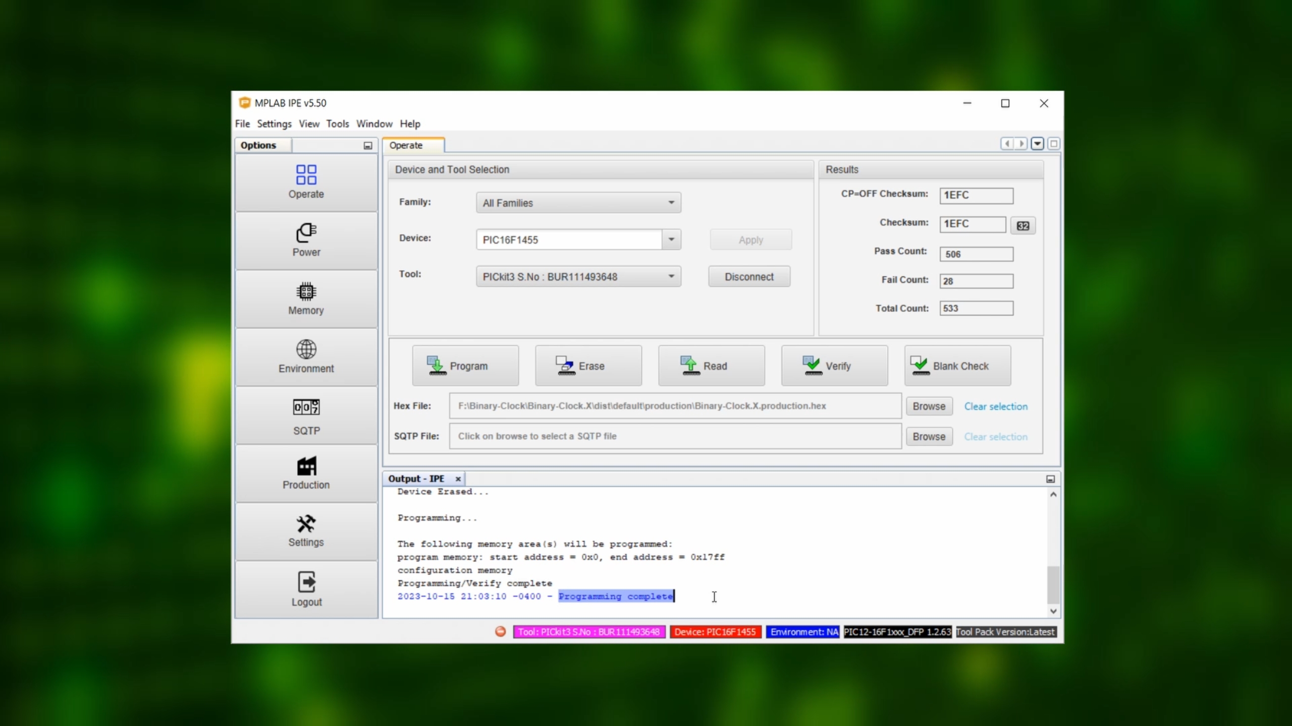
Click on the "Program" symbol, and after a few seconds we are done, and the MPLAB IPE tells us “Programming complete.”
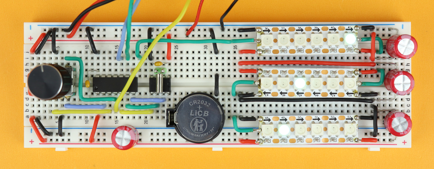
You can now remove the wires from the PICkit3, and your binary clock is ready to go:
Now, this video is supposed to be a tutorial, so I always want to show you exactly how and why something works. There is just one problem: the code for our binary clock ended up being around 800 lines, which is a bit on the long side to cover in this video here...
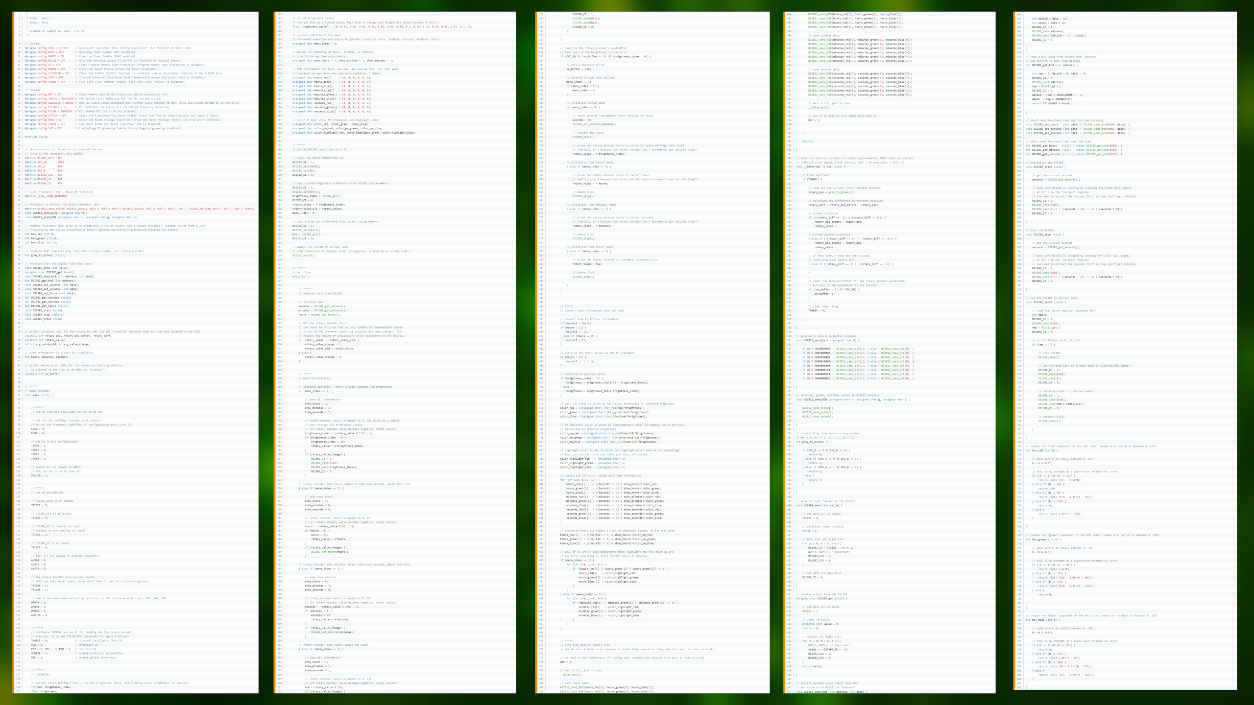
But, believe it or not, we actually covered a lot of parts of this program in previous tutorials:
The green part deals with the rotary encoder, the orange part talks to the DS1302 real-time clock, and the blue part is the code for the WS2812 LEDs.
But if you are interested in the details of the code, keep reading. In this article I cannot go through all 800 lines, it's just too much. In an earlier version of the video, I had a whole section that went through the main pieces of the code, and it just took forever... So what I want to do here is to give you several stages of the code (together with their .hex-files) where you can piece together, hopefully, how I wrote the whole thing.
I think that in combination with the tutorials on the rotary encoder, the WS2812 “NeoPixel” LEDs, and the DS1302 real-time clock IC this will give you a pretty good idea of how everything works :) So let's go!
- Program speed. The program has to run at 48MHz because we are driving WS2812 LEDs that need very short data signals. So, let's first make sure that the internal oscillator is really set to 48MHz, and to test if it works, we can write a simple main loop that is supposed to make an LED blink at 1Hz, under the assumption that the code runs at 48MHz. You can connect this LED at the data output for simplicity. And if it really blinks at 1Hz, then we know that our program really runs at 48Mhz. (Files: main-1.c, code-1.hex.)
- LEDs. Let's make sure we can drive the LEDs. This is important because the WS2812 data protocol is quite time-critical. We have 18 LEDs organized in three rows with six LEDs each. So we can write a small program that sends out fixed colors to the LEDs just for fun, just to see how it works, and to get the ordering right. Then we can make it send out a fixed time in blue (say, 01:23:45), with an orange PM indicator. (Files: main-2.c, code-2.hex.)
- Input device. Next, let's make sure we can read out the rotary encoder. We need an interrupt service routine for that, so let's add that. We need to remember to disable interrupts before writing out data to our LEDs, and re-enable them afterwards. This is is important so that LED data is sent out in one piece, otherwise it could be interrupted by, well, the interrupt, and we don't want that because it would make our LEDs display nonsense. And then I added a simple test of the rotary encoder and made it adjust the brightness of all blue LEDs. And the pushbutton turns the orange LED on and off. We should now have a working input device. (Files: main-3.c, code-3.hex.)
- Reading out the time. Time to get serious. We need to connect to the DS1302 real-time clock, and for now all we need is to make sure that the DS1302 is really running properly in 24-hour mode, and then we need to read out the hours, minutes, and seconds. At this point we should also define some arrays that store the LED color data, for simplicity. And we need to convert the time information into the LED pattern that we want to display. This part is a bit tricky since it involves arrays and more advanced coding. (Files: main-4.c, code-4.hex.)
- Making the time adjustable. For this step we need to talk to the rotary encoder, and implement a basic menu functionality so that whenever we press the rotary encoder, we jump to the next step in the menu, and whenever we turn it, we can adjust the hours and minutes. After these values change, we need to update them and send them back to the DS1302. At this point we basically have a functioning clock. (Files: main-5.c, code-5.hex.)
- Add some pizzazz with some finishing touches. Let's highlight the hours or minutes row when we are in the time-setting menu with a custom background color. Also, let's make the LED color adjustable as a third menu option, and for that we can borrow HSV curves from this library page and implement them in C for the PIC. This way we can cycle through a lot of colors with just one knob. It's not perfect, but I think for this project it's good enough. And the PM indicator's HSV value is shifted by 128 so that its color is complementary to those of the main LEDs. Whenever we are not in the time-setting menu, let's add a brightness functionality that lets us dim the LEDs using a brightness table made of 16 different brightness levels. All these floating point multiplications really make the program size balloon up, and we ended up at around 70% of program space, and almost 40% of data space. Quite a lot. (Files: main-6.c, code-6.hex.)
Let me know if you find this helpful, or if something does not make sense, I am happy to hear from you :)
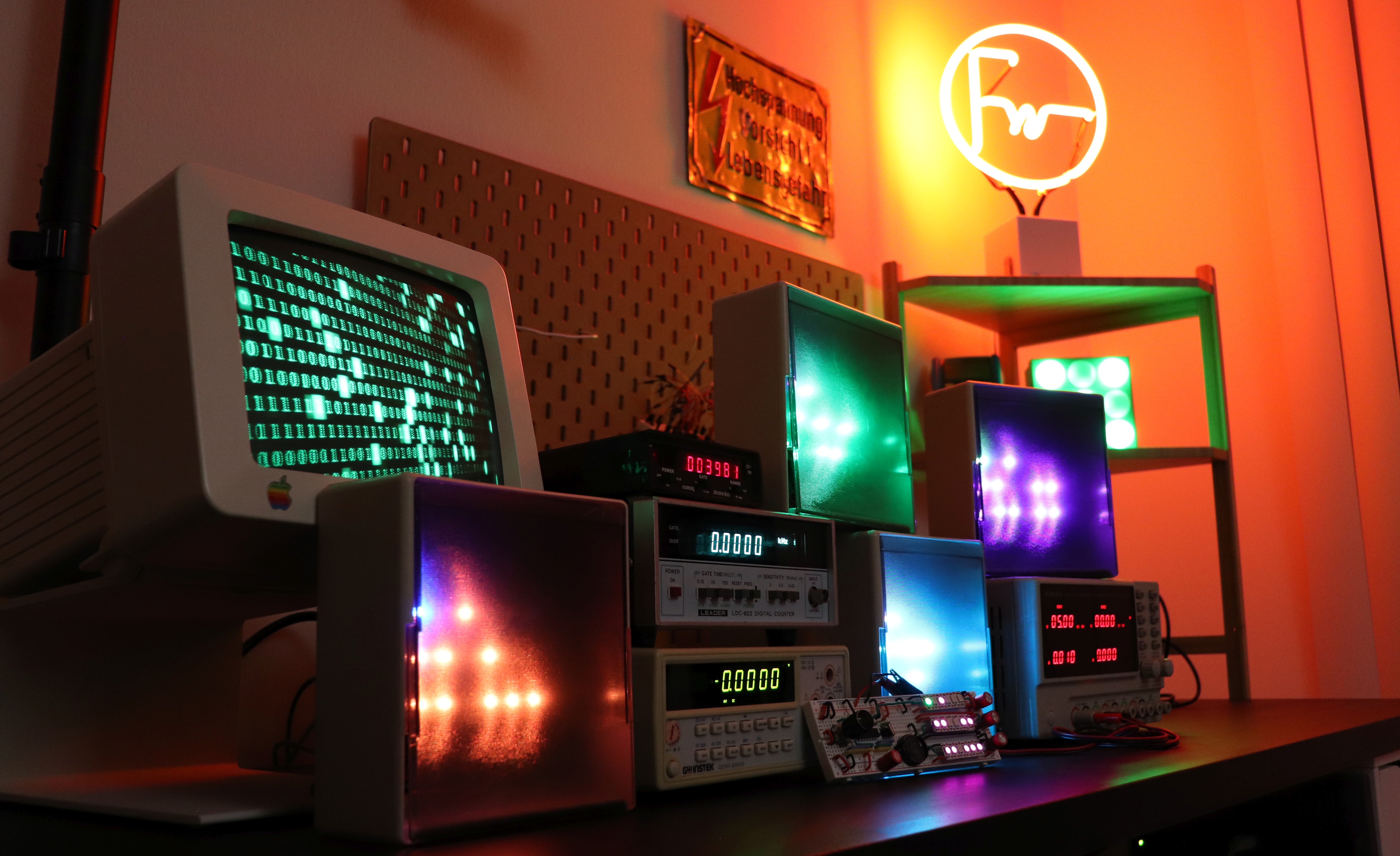
Finished binary clock
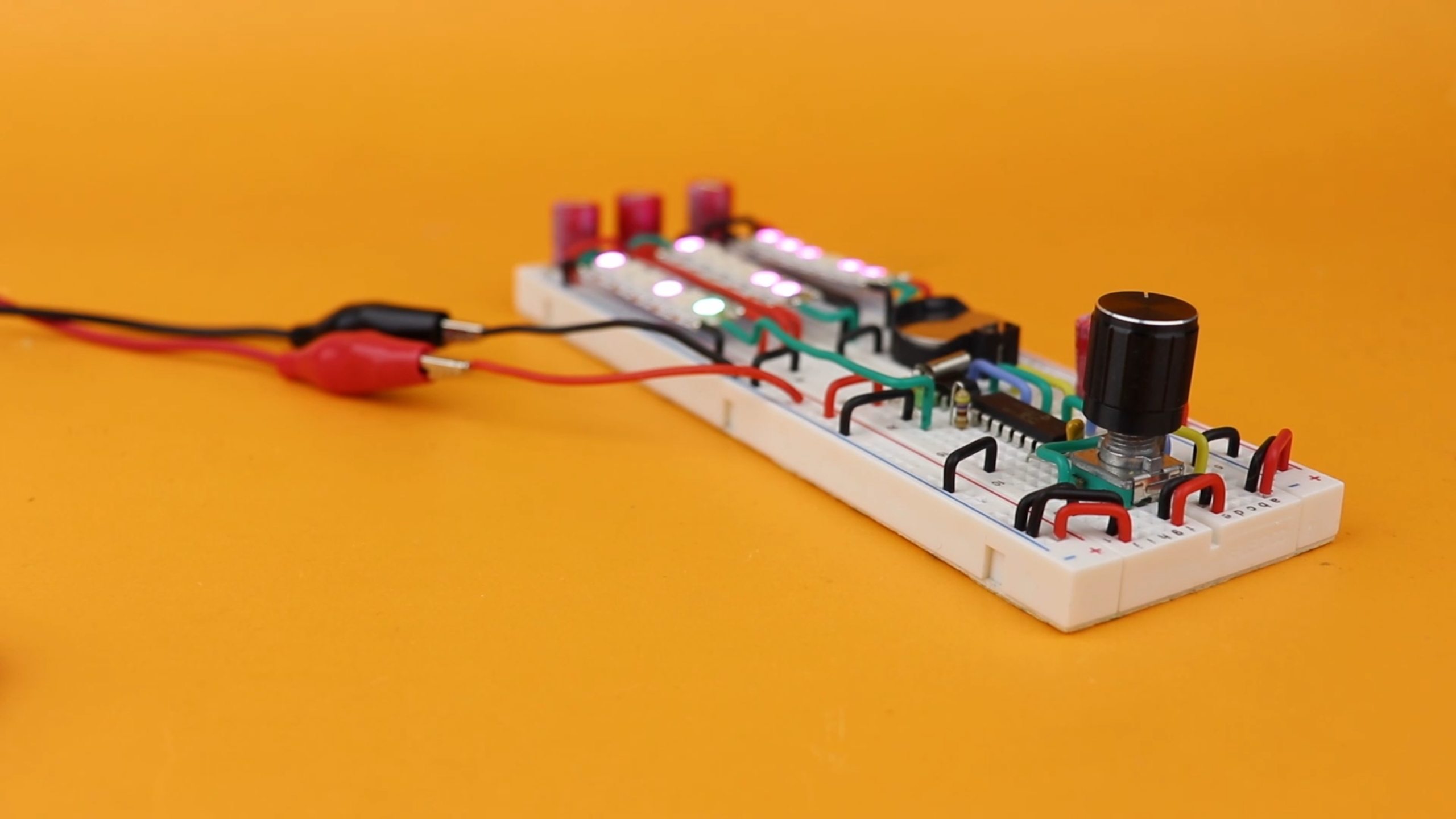
Chances are that when you build this clock on a breadboard you will run into some problems, so I want to save you some trouble and talk a little bit about that.
If you think about it, the maximum current is quite high: we have 54 LEDs in total, which, at full brightness, each take 20mA. That's around 1A in total. Okay, maybe it doesn't sound like much, but what does it mean on our breadboard?
- First, think about voltage drops. At 1A, a resistance of only 1Ω makes 1V drop, which is huge when working with 4.5V! And a 1Ω resistance is nothing on a breadboard, you can easily get resistances of dozens of Ohms. You could have 4.5V where the battery cable plugs in, but only 3V a few centimeters further. Not good. So: we have to make sure that all connections from the power rail to the LED strips are as conductive as possible, and sometimes it helps to insert additional wires to cut down the resistance.
- And second, there can be power surges whenever a lot of LEDs turn ON or when we increase the brightness rapidly, and for that I added the 100μF capacitors, one for each LED strip segment. It really helps to stabilize things, because they act as little power reservoirs. And, because they are close to their LEDs, the resistance in the breadboard connections also doesn't play that much of a role. If you want, remove the capacitors, and see what happens.
Now, don't get discouraged, I think this is a great project to do, but I just want to give you some pointers in case something goes wrong :) Basically: use a good breadboard with good connectivity, use a voltmeter to verify that there are no crazy voltage drops, and don't leave out the big capacitors.
Alternative build
While you can totally make it work on a breadboard, breadboard circuits are not always ideal. For that reason I thought I would build a few more of those binary clocks, but this time around, I wanted to use perfboards and solder everything. While that removes the resistance problem that you have with poor contacts on breadboards, it does take a fair amount longer:
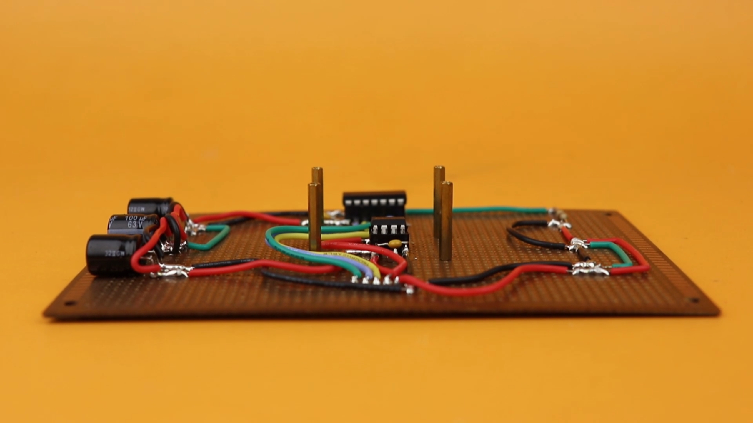
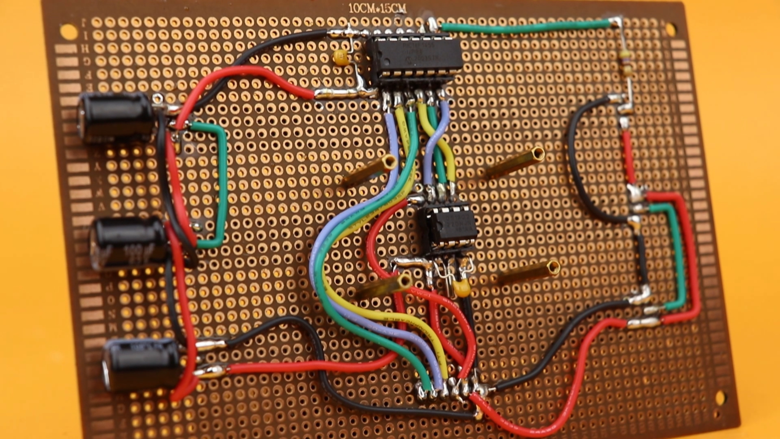
Yes, that takes a long time to solder. While it is not a lot of wires, everything is cut to length and I at least tried to make it look acceptable.
As you saw at the beginning of this video, I then installed these boards in old-school floppy disc fold out cases that I found at a thrift store. The perfboard size worked perfectly with the size of the fold out piece, and I used brass standoffs to mount the boards in place. And I really loved how everything came together.
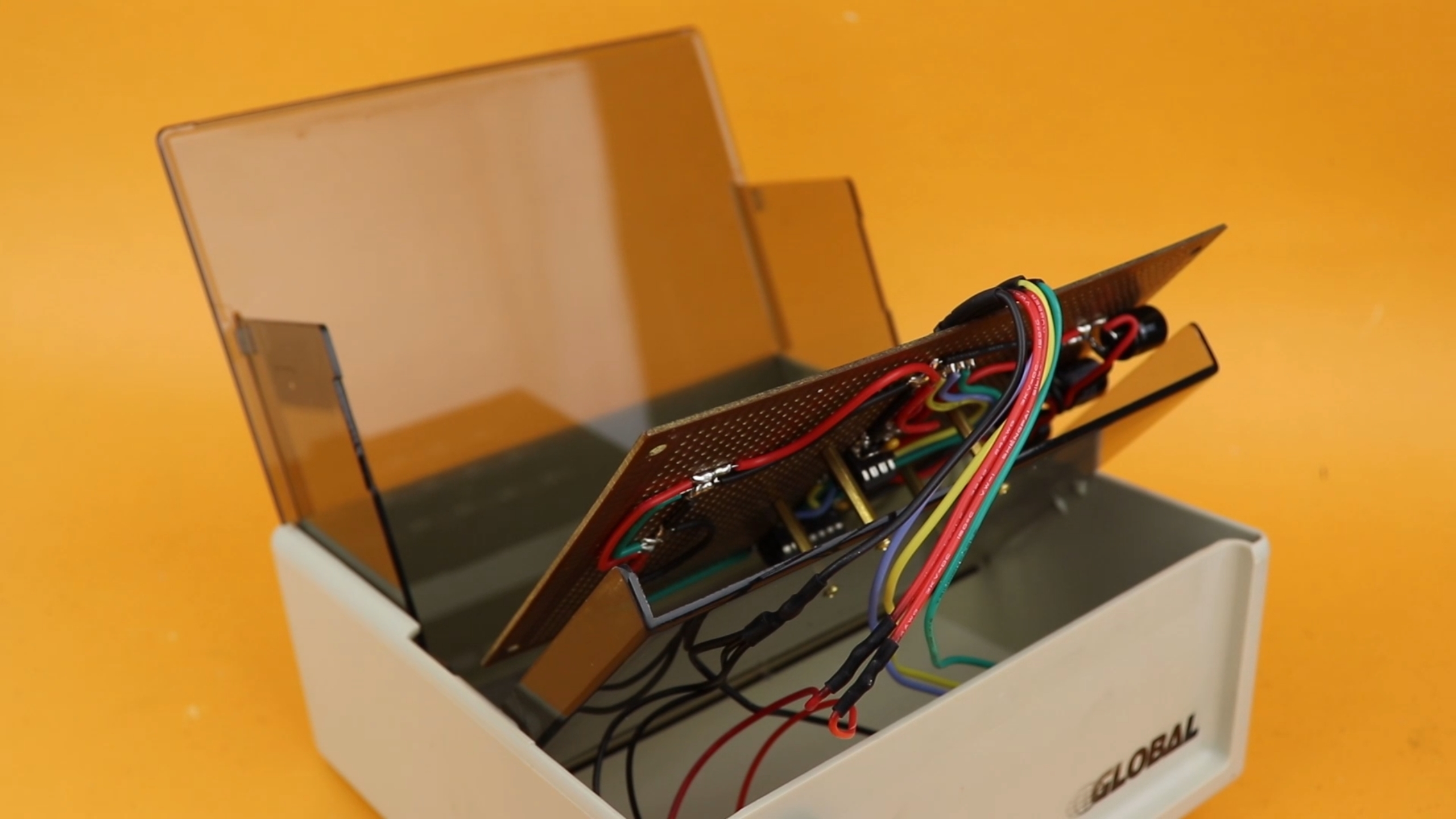
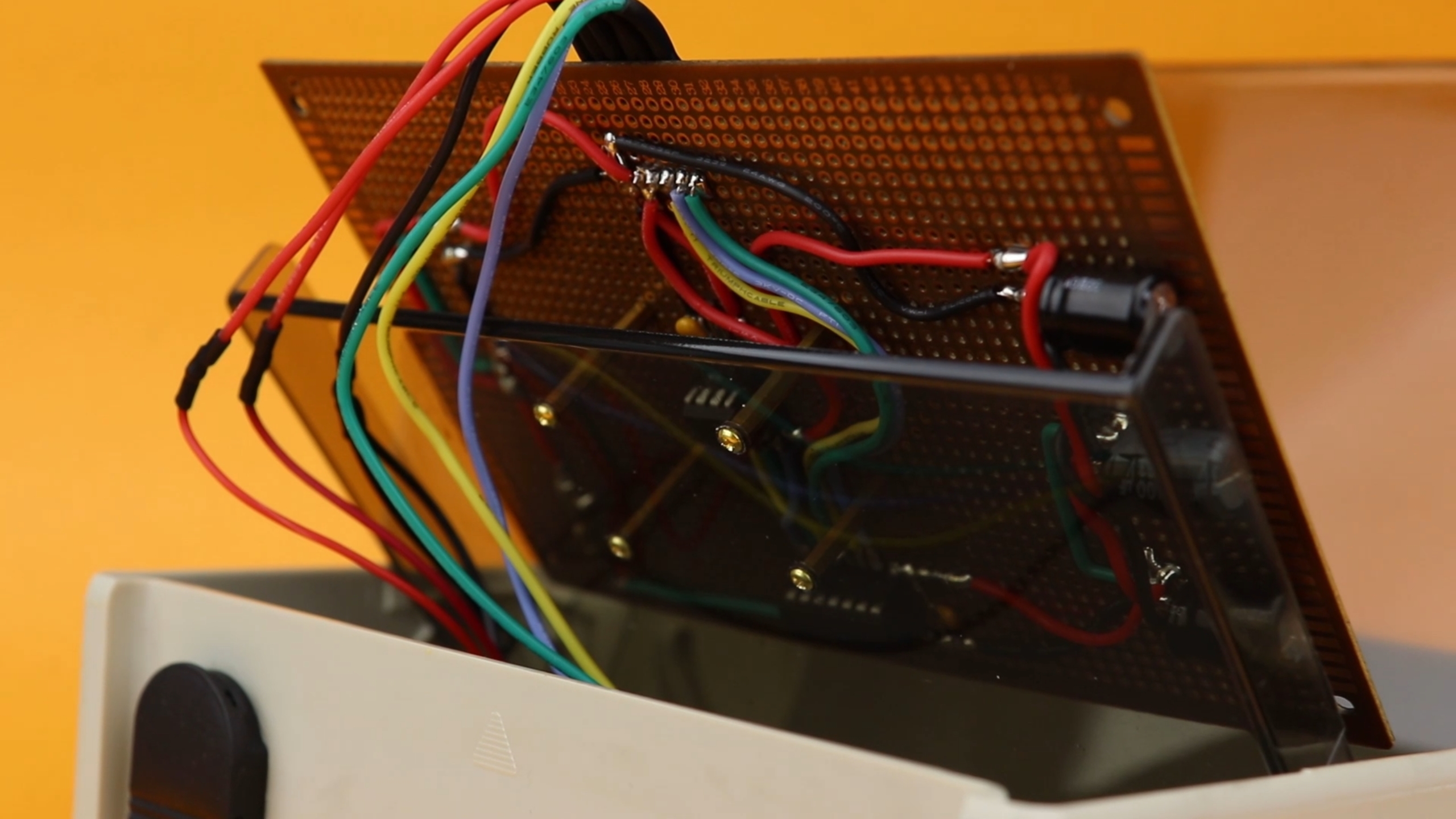
The knob, the backup battery, and the power input plug into connectors so that we can remove the board, if we ever need to. The knob and the USB type C port are on the back of the case, and the battery is mounted separately under the case so that it can be replaced easily.
Now I thought about spray-painting the housing itself, but then I realized that I already quite liked how they looked, so I kept them as is.
YouTube video
I covered this entire project in a dedicated YouTube video:
Final thoughts
I really hope I could inspire you to give it a go and try to build this clock yourself, I promise, it will be fun. Thank you so much for reading this article, let me know what else you want to learn, and I'll see you next time!
Appendix
/*
 * File:   main.c
 * Author: boos
 *
 * Created on August 12, 2023, 7:39 PM
 */

// CONFIG1
#pragma config FOSC = INTOSC    // Oscillator Selection Bits (INTOSC oscillator: I/O function on CLKIN pin)
#pragma config WDTE = OFF       // Watchdog Timer Enable (WDT disabled)
#pragma config PWRTE = OFF      // Power-up Timer Enable (PWRT disabled)
#pragma config MCLRE = OFF      // MCLR Pin Function Select (MCLR/VPP pin function is digital input)
#pragma config CP = OFF         // Flash Program Memory Code Protection (Program memory code protection is disabled)
#pragma config BOREN = OFF      // Brown-out Reset Enable (Brown-out Reset disabled)
#pragma config CLKOUTEN = OFF   // Clock Out Enable (CLKOUT function is disabled. I/O or oscillator function on the CLKOUT pin)
#pragma config IESO = OFF       // Internal/External Switchover Mode (Internal/External Switchover Mode is disabled)
#pragma config FCMEN = OFF      // Fail-Safe Clock Monitor Enable (Fail-Safe Clock Monitor is disabled)

// CONFIG2
#pragma config WRT = OFF        // Flash Memory Self-Write Protection (Write protection off)
#pragma config CPUDIV = NOCLKDIV// CPU System Clock Selection Bit (NO CPU system divide)
#pragma config USBLSCLK = 48MHz // USB Low Speed Clock Selection bit (System clock expects 48 MHz, FS/LS USB CLKENs divide-by is set to 8.)
#pragma config PLLMULT = 3x     // PLL Multipler Selection Bit (3x Output Frequency Selected)
#pragma config PLLEN = ENABLED  // PLL Enable Bit (3x or 4x PLL Enabled)
#pragma config STVREN = OFF     // Stack Overflow/Underflow Reset Enable (Stack Overflow or Underflow will not cause a Reset)
#pragma config BORV = LO        // Brown-out Reset Voltage Selection (Brown-out Reset Voltage (Vbor), low trip point selected.)
#pragma config LPBOR = OFF      // Low-Power Brown Out Reset (Low-Power BOR is disabled)
#pragma config LVP = OFF        // Low-Voltage Programming Enable (Low-voltage programming disabled)

#include <xc.h>


// abbreviations for locations of externa devices
// (this is not necessary, but useful)
#define WS2812_DATA  RC2
#define ENC_SW       !RA3
#define ENC_A        RA4
#define ENC_B        RA5
#define DS1302_CLK   RC3
#define DS1302_IO    RC4
#define DS1302_CE    RC5


// functions to control the WS2812 NeoPixel LEDs
#define WS2812_send_bit(b) WS2812_DATA=1; NOP(); NOP(); NOP(); WS2812_DATA=b; NOP(); NOP(); NOP(); NOP(); WS2812_DATA=0; NOP(); NOP(); NOP(); NOP();
void WS2812_send_byte (unsigned char b);
void WS2812_send_RGB (unsigned char r, unsigned char g, unsigned char b);

// helpful functions that allow us to sweep over a lot of colors with a single variable h (taking values from 0..255)
// (inspired by the curves presented on https://github.com/FastLED/FastLED/wiki/FastLED-HSV-Colors)
int hsv_red (int h);
int hsv_green (int h);
int hsv_blue (int h);

// function that converts Gray code into a binary number (for rotary encoder)
int gray_to_binary (void);

// functions for the DS1302 real-time clock
void DS1302_send (int value);
unsigned char DS1302_get (void);
void DS1302_set_bcd (int address, int data);
int DS1302_get_bcd (int address);
void DS1302_set_seconds (int data);
void DS1302_set_minutes (int data);
void DS1302_set_hours (int data);
int DS1302_get_seconds (void);
int DS1302_get_minutes (void);
int DS1302_get_hours (void);
void DS1302_start (void);
void DS1302_stop (void);
void DS1302_set24 (void);


// global variables used for the rotary encoder (we add "volatile" wherever they are used and updated in the ISR)
volatile int rotary_pos, rotary_pos_before, rotary_diff;
volatile int rotary_value;
int rotary_value_old, rotary_value_change;

// time information is global for simplicity
int hours, minutes, seconds;

// global debounce variable for the rotary encoder's pushbutton
// (is altered in the ISR, so we make it "volatile")
volatile int sw_buffer;


// *****
// main function
void main (void) {


    // *****
    // set up internal oscillator to run at 48 MHz

    // set the SCS settings (system clock select)
    // to use the frequency specified in configuration word (line 22)
    SCS0 = 0;
    SCS1 = 0;

    // set to 16 MHz configuration
    IRCF0 = 1;
    IRCF1 = 1;
    IRCF2 = 1;
    IRCF3 = 1;

    // enable PLL to result in 48MHz
    // (PLL is set to 3x in line 23)
    SPLLEN = 1;


    // *****
    // set up peripherals

    // WS2812_DATA is an output
    TRISC2 = 0;

    // DS1302_CLK is an output
    TRISC3 = 0;

    // DS1302_IO is usually an input
    // (unless we are reading in data)
    TRISC4 = 1;

    // DS1302_CE is an output
    TRISC5 = 0;

    // turn off all analog to digital converters
    ANSA4 = 0;
    ANSC2 = 0;
    ANSC3 = 0;

    // the rotary encoder pins are all inputs
    // (RA3 can only be an input, so we don't have to set its tristate register)
    TRISA4 = 1;
    TRISA5 = 1;

    // enable the weak internal pullup resistors on the rotary encoder inputs RA3, RA4, RA5
    WPUA3 = 1;
    WPUA4 = 1;
    WPUA5 = 1;
    nWPUEN = 0;


    // *****
    // configure TIMER0 (we use it for reading out the rotary encoder)
	// (see Sec. 19 in the PIC16F1455 datasheet for specifications)
    TMR0CS = 0;                 // internal oscillator (Fosc/4)
    PSA = 0;                    // prescaler ON
    PS2 = 0; PS1 = 1; PS0 = 1;  // set to 1:16
    TMR0IE = 1;                 // enable interrupt on overflow
    GIE = 1;                    // enable global interrupts


    // *****
    // variables

    // current color setting ("hue"), current brightness level, and floating point brightness (in percent)
    int hue, brightness_index;
    float brightness;

    // 16 LED brightness levels
    // (We use this as a lookup table, feel free to change your brightness levels between 0 and 1.)
    float brightness_table[] = {0, 0.01, 0.02, 0.03, 0.04, 0.05, 0.06, 0.08, 0.1, 0.19, 0.25, 0.34, 0.42, 0.52, 0.7, 1};

    // current position of the menu
    // (0=normal operation and adjust brightness, 1=adjust hours, 2=adjust minutes, 3=adjust color)
    unsigned char menu_index = 0;

    // allows for blanking of hours, minutes, or seconds
    // (useful during time adjustments)
    unsigned char show_hours = 1, show_minutes = 1, show_seconds = 1;

    // RGB information for hour, minutes, and second LEDs (six LEDs each)
    // (separate arrays make the code more readable, I think)
    unsigned char hours_red[]     = {0, 0, 0, 0, 0, 0};
    unsigned char hours_green[]   = {0, 0, 0, 0, 0, 0};
    unsigned char hours_blue[]    = {0, 0, 0, 0, 0, 0};
    unsigned char minutes_red[]   = {0, 0, 0, 0, 0, 0};
    unsigned char minutes_green[] = {0, 0, 0, 0, 0, 0};
    unsigned char minutes_blue[]  = {0, 0, 0, 0, 0, 0};
    unsigned char seconds_red[]   = {0, 0, 0, 0, 0, 0};
    unsigned char seconds_green[] = {0, 0, 0, 0, 0, 0};
    unsigned char seconds_blue[]  = {0, 0, 0, 0, 0, 0};

    // color of main LEDs and PM indicator
    unsigned char color_red, color_green, color_blue;
    unsigned char color_pm_red, color_pm_green, color_pm_blue;


    // *****
    // set up DS1302 real-time clock IC

    // clear the WRITE PROTECTION bit
    DS1302_CE = 1;
    DS1302_send(0x8e);
    DS1302_send(0);
    DS1302_CE = 0;

    // read stored brightness preference from DS1302 custom memory
    DS1302_CE = 1;
    DS1302_send(0xc1);
    brightness_index = DS1302_get();
    DS1302_CE = 0;
    rotary_value = 4*brightness_index;

    // read stored hue preference from DS1302 custom memory
    DS1302_CE = 1;
    DS1302_send(0xc3);
    hue = DS1302_get();
    DS1302_CE = 0;

    // always set DS1302 to 24-hour mode
    // (the conversion to 12-hour mode, if required, is done by us in the code.)
    DS1302_set24();


    // *****
    // main loop
    while (1) {


        // *****
        // read out data from DS1302

        // retrieve time
        seconds = DS1302_get_seconds();
        minutes = DS1302_get_minutes();
        hours = DS1302_get_hours();

        // Did the rotary encoder turn?
        // (We check for this so that we only update the information stored
        // in the DS1302 whenever something actually has been changed. This
        // reduces the amount of unnecessary write operations to the DS1302.)
        if (rotary_value != rotary_value_old) {
            rotary_value_change = 1;
            rotary_value_old = rotary_value;
        } else {
            rotary_value_change = 0;
        }


        // *****
        // menu functionality

        // standard operation, rotary encoder changes LED brightness
        if (menu_index == 0) {

            // show all information
            show_hours = 1;
            show_minutes = 1;
            show_seconds = 1;

            // rotary encoder value is mapped to 0..28, which is a double
            // pass through all brightness levels
            // (if rotary encoder value becomes negative, reset values)
            brightness_index = (rotary_value % 116) / 4;
            if (brightness_index < 0) {
                brightness_index = 28;
                rotary_value = 4*brightness_index;
            }
            if (rotary_value_change) {
                DS1302_CE = 1;
                DS1302_send(0xc0);
                DS1302_send(brightness_index);
                DS1302_CE = 0;
            }

        // rotary encoder sets hours, blank minutes and seconds, pause the clock
        } else if (menu_index == 1) {

            // only show hours
            show_hours = 1;
            show_minutes = 0;
            show_seconds = 0;

            // rotary encoder value is mapped to 0..23
            // (if rotary encoder value becomes negative, reset values)
            hours = (rotary_value % 96) / 4;
            if (hours < 0) {
                hours = 23;
                rotary_value = 4*hours;
            }
            if (rotary_value_change) {
                DS1302_set_hours(hours);
            }

        // rotary encoder sets minutes, blank hours and seconds, pause the clock
        } else if (menu_index == 2) {

            // only show minutes
            show_hours = 0;
            show_minutes = 1;
            show_seconds = 0;

            // rotary encoder value is mapped to 0..59
            // (if rotary encoder value becomes negative, reset values)
            minutes = (rotary_value % 240) / 4;
            if (minutes < 0) {
                minutes = 59;
                rotary_value = 4*minutes;
            }
            if (rotary_value_change) {
                DS1302_set_minutes(minutes);
            }

        // rotary encoder sets color, pause the clock
        } else if (menu_index == 3) {

            // show all information
            show_hours = 1;
            show_minutes = 1;
            show_seconds = 1;

            // rotary encoder value is mapped to 0..255
            // (if rotary encoder value becomes negative, reset values)
            hue = rotary_value % 256;
            if (rotary_value_change) {
                DS1302_CE = 1;
                DS1302_send(0xc2);
                DS1302_send(hue);
                DS1302_CE = 0;
            }

        }

        // react to the rotary encoder's pushbutton
        if (ENC_SW && (sw_buffer == 0)) {

            // refill debounce buffer
            sw_buffer = 500;

            // advance through menu options
            menu_index += 1;
            if (menu_index > 3) {
                menu_index = 0;
            }

            // initialize normal mode
            if (menu_index == 0) {

                // reset seconds (convenient after setting the time)
                seconds = 0;
                DS1302_set_seconds(seconds);

                // restart the clock
                DS1302_start();

                // prime the rotary encoder value to currently selected dimming level
                // (multiply by 4 because our rotary encoder has 4 increments per tactile "step")
                rotary_value = 4*brightness_index;

            // initialize "set hours" mode
            } else if (menu_index == 1) {

                // prime the rotary encoder value to current hours
                // (multiply by 4 because our rotary encoder has 4 increments per tactile "step")
                rotary_value = 4*hours;

                // pause clock
                DS1302_stop();

            // initialize "set minutes" mode
            } else if (menu_index == 2) {

                // prime the rotary encoder value to current minutes
                // (multiply by 4 because our rotary encoder has 4 increments per tactile "step")
                rotary_value = 4*minutes;

                // pause clock
                DS1302_stop();

            // initialize "set color" mode
            } else if (menu_index == 3) {

                // prime the rotary encoder to currently selected color
                rotary_value = hue;

                // pause clock
                DS1302_stop();

            }

        }


        // *****
        // convert time information into LED data

        // convert time to 12 hour information
        int hours12 = hours;
        if (hours > 12) {
            hours12 -= 12;
        } else if (hours == 0) {
            hours12 = 12;
        }

        // bit 5 of the hours serves as the PM indicator
        if (hours > 11) {
            hours12 |= 1 << 5;
        }

        // determine brightness level
        if (brightness_index > 15) {
            brightness = brightness_table[29 - brightness_index];
        } else {
            brightness = brightness_table[brightness_index];
        }

        // main LED color is given by hue value, multiplied by selected brightness
        color_red = (unsigned char) (hsv_red(hue)*brightness);
        color_green = (unsigned char) (hsv_green(hue)*brightness);
        color_blue = (unsigned char) (hsv_blue(hue)*brightness);

        // PM indicator color is given by complementary color (by adding 128 to the hue),
        // multiplied by selected brightness
        color_pm_red = (unsigned char) (hsv_red(hue+128)*brightness);
        color_pm_green = (unsigned char) (hsv_green(hue+128)*brightness);
        color_pm_blue = (unsigned char) (hsv_blue(hue+128)*brightness);

        // update all LED color values with time information
        for (int i=0; i<=5; i++) {

            hours_red[i]     = ((hours12 >> i) & show_hours)*color_red;
            hours_green[i]   = ((hours12 >> i) & show_hours)*color_green;
            hours_blue[i]    = ((hours12 >> i) & show_hours)*color_blue;
            minutes_red[i]   = ((minutes >> i) & show_minutes)*color_red;
            minutes_green[i] = ((minutes >> i) & show_minutes)*color_green;
            minutes_blue[i]  = ((minutes >> i) & show_minutes)*color_blue;
            seconds_red[i]   = ((seconds >> i) & show_seconds)*color_red;
            seconds_green[i] = ((seconds >> i) & show_seconds)*color_green;
            seconds_blue[i]  = ((seconds >> i) & show_seconds)*color_blue;

        }

        // overwrite hours bit number 5 with PM indicator status, in its own color
        hours_red[5]   = ((hours12 >> 5) & show_hours)*color_pm_red;
        hours_green[5] = ((hours12 >> 5) & show_hours)*color_pm_green;
        hours_blue[5]  = ((hours12 >> 5) & show_hours)*color_pm_blue;


        // *****
        // send time data to WS2812 LEDs
        // (we do this without loops because it would delay execution time, and this part is time critical)

        // we need to turn interrupts OFF during data transmission because this part is time critical
        GIE = 0;

        // send hours data
        WS2812_send_RGB(hours_red[5], hours_green[5], hours_blue[5]);
        WS2812_send_RGB(hours_red[4], hours_green[4], hours_blue[4]);
        WS2812_send_RGB(hours_red[3], hours_green[3], hours_blue[3]);
        WS2812_send_RGB(hours_red[2], hours_green[2], hours_blue[2]);
        WS2812_send_RGB(hours_red[1], hours_green[1], hours_blue[1]);
        WS2812_send_RGB(hours_red[0], hours_green[0], hours_blue[0]);

        // send minutes data
        WS2812_send_RGB(minutes_red[0], minutes_green[0], minutes_blue[0]);
        WS2812_send_RGB(minutes_red[1], minutes_green[1], minutes_blue[1]);
        WS2812_send_RGB(minutes_red[2], minutes_green[2], minutes_blue[2]);
        WS2812_send_RGB(minutes_red[3], minutes_green[3], minutes_blue[3]);
        WS2812_send_RGB(minutes_red[4], minutes_green[4], minutes_blue[4]);
        WS2812_send_RGB(minutes_red[5], minutes_green[5], minutes_blue[5]);

        // send seconds data
        WS2812_send_RGB(seconds_red[5], seconds_green[5], seconds_blue[5]);
        WS2812_send_RGB(seconds_red[4], seconds_green[4], seconds_blue[4]);
        WS2812_send_RGB(seconds_red[3], seconds_green[3], seconds_blue[3]);
        WS2812_send_RGB(seconds_red[2], seconds_green[2], seconds_blue[2]);
        WS2812_send_RGB(seconds_red[1], seconds_green[1], seconds_blue[1]);
        WS2812_send_RGB(seconds_red[0], seconds_green[0], seconds_blue[0]);

        // now it is safe to turn interrupts back on
        GIE = 1;


    }

    return;

}

// interrupt service routine (is called approximately 2930 times per second)
// (48MHz/4 clock speed, 8-bit counter, with 1:16 prescaler = 2930 Hz)
void __interrupt () isr (void) {

    // timer overflow?
    if (TMR0IF) {

        // read out the current rotary encoder position
        rotary_pos = gray_to_binary();

        // calculate the difference to previous position
        rotary_diff = rotary_pos_before - rotary_pos;

        // turned clockwise
        if (((rotary_diff == -1) || (rotary_diff == 3))) {
            rotary_pos_before = rotary_pos;
            rotary_value++;

        // turned counter-clockwise
        } else if (((rotary_diff == 1) || (rotary_diff == -3))) {
            rotary_pos_before = rotary_pos;
            rotary_value--;

        // in this case, a step has been missed
        // (best practice: ignore it!)
        } else if ((rotary_diff == 2) || (rotary_diff == -2)) {

        }

        // clear the debounce buffer for the rotary encoder pushbutton,
        // but only if the pushbutton is not pressed
        if ((sw_buffer > 0) && !ENC_SW) {
            sw_buffer--;
        }

        // clear timer flag
        TMR0IF = 0;

    }

}

// send out a byte b in WS2812 protocol
void WS2812_send_byte (unsigned char b) {

    if (b & 0b10000000) { WS2812_send_bit(1); } else { WS2812_send_bit(0); }
    if (b & 0b01000000) { WS2812_send_bit(1); } else { WS2812_send_bit(0); }
    if (b & 0b00100000) { WS2812_send_bit(1); } else { WS2812_send_bit(0); }
    if (b & 0b00010000) { WS2812_send_bit(1); } else { WS2812_send_bit(0); }
    if (b & 0b00001000) { WS2812_send_bit(1); } else { WS2812_send_bit(0); }
    if (b & 0b00000100) { WS2812_send_bit(1); } else { WS2812_send_bit(0); }
    if (b & 0b00000010) { WS2812_send_bit(1); } else { WS2812_send_bit(0); }
    if (b & 0b00000001) { WS2812_send_bit(1); } else { WS2812_send_bit(0); }

}

// send red, green, and blue values in WS2812 protocol
void WS2812_send_RGB (unsigned char r, unsigned char g, unsigned char b) {

    WS2812_send_byte(g);
    WS2812_send_byte(r);
    WS2812_send_byte(b);

}

// convert Gray code into a binary number
// 00 -> 0, 01 -> 1, 11 -> 2, 10 -> 3
int gray_to_binary () {

    if (ENC_A == 0 && ENC_B == 0) {
        return 0;
    } else if (ENC_A == 0 && ENC_B == 1) {
        return 1;
    } else if (ENC_A == 1 && ENC_B == 1) {
        return 2;
    } else {
        return 3;
    }

}

// send the byte "value" to the DS1302
void DS1302_send (int value) {

    // set data port as output
    TRISC4 = 0;
    ANSC2 = 0;

    // auxiliary index variable
	int n = 0;

    // loop over all eight bits
	for (n = 0; n < 8; n++) {
        DS1302_IO = (value >> n) & 1;
        NOP(); // important!
        DS1302_CLK = 1;
        DS1302_CLK = 0;
    }

}

// receive a byte from the DS1302
unsigned char DS1302_get (void) {

    // set data port as input
    TRISC4 = 1;
    ANSC2 = 0;

    // dummy variables
    unsigned char value = 0;
    char n = 0;

    // collect all eight bits
    for (n = 0; n < 8; n++) {
        NOP(); // important!
        value |= (DS1302_IO << n);
        DS1302_CLK = 1;
        DS1302_CLK = 0;
    }
    return value;

}

// convert decimal value "data" into BCD
// and store it in DS1302 at "address"
void DS1302_set_bcd (int address, int data) {

    int data10 = data / 10;
    int data1 = data % 10;
    DS1302_CE = 1;
    DS1302_send(address);
    DS1302_send((data10 << 4) | data1);
    DS1302_CE = 0;

}

// read a BCD value from DS1302 from "address"
// and convert it back into decimal
int DS1302_get_bcd (int address) {

    int tmp = 0, data10 = 0, data1 = 0;
    DS1302_CE = 1;
    DS1302_send(address);
    tmp = DS1302_get();
    DS1302_CE = 0;
    data10 = (tmp & 0b01110000) >> 4;
    data1  = tmp & 0b00001111;
    return 10*data10 + data1;

}

// short-hand functions that set the time directly
void DS1302_set_hours   (int data) { DS1302_set_bcd(0x84, data); }
void DS1302_set_minutes (int data) { DS1302_set_bcd(0x82, data); }
void DS1302_set_seconds (int data) { DS1302_set_bcd(0x80, data); }

// short-hand functions that read the time
int DS1302_get_hours   (void) { return DS1302_get_bcd(0x85); }
int DS1302_get_minutes (void) { return DS1302_get_bcd(0x83); }
int DS1302_get_seconds (void) { return DS1302_get_bcd(0x81); }

// initialize the DS1302
void DS1302_start (void) {

    // get the current seconds
    seconds = DS1302_get_seconds();

    // make sure DS1302 is running by clearing the CLOCK HALT signal
    // at bit 7 in the "seconds" register
    // (we need to extract the seconds first so they don't get deleted)
    DS1302_CE = 1;
    DS1302_send(0x80);
    DS1302_send(0<<7 | ((seconds / 10) << 4) | (seconds % 10));
    DS1302_CE = 0;

}

// stop the DS1302
void DS1302_stop (void) {

    // get the current seconds
    seconds = DS1302_get_seconds();

    // make sure DS1302 is stopped by setting the CLOCK HALT signal
    // at bit 7 in the "seconds" register
    // (we need to extract the seconds first so they don't get deleted)
    DS1302_CE = 1;
    DS1302_send(0x80);
    DS1302_send(1<<7 | ((seconds / 10) << 4) | (seconds % 10));
    DS1302_CE = 0;

}

// set the DS1302 to 24-hour mode
void DS1302_set24 (void) {

    // get the current hours
    hours = DS1302_get_hours();

    // make sure DS1302 is running in 24-hour mode by setting bit 7
    // in the "hours" register
    // (we need to extract the hours first so they don't get deleted)
    DS1302_CE = 1;
    DS1302_send(0x84);
    DS1302_send(1<<7 | ((hours / 10) << 4) | (hours % 10) );
    DS1302_CE = 0;

}

// create the "red" component of the HSV color, based on h (which is between 0..255)
int hsv_red (int h) {

    // make sure h is really between 0..255
    h = h & 0xff;

    // this is my attempt at a piece-wise defined HSV curve
    if ((h >= 0) && (h <= 32)) {
        return (int) (255 - 2.66*h);
    } else if (h <= 64) {
        return 170;
    } else if (h <= 96) {
        return (int) (170 - 5.31*(h - 64));
    } else if (h <= 160) {
        return 0;
    } else {
        return (int) 2.68*(h - 160);
    }

}

// create the "green" component of the HSV color, based on h (which is between 0..255)
int hsv_green (int h) {

    // make sure h is really between 0..255
    h = h & 0xff;

    // this is my attempt at a piece-wise defined HSV curve
    if ((h >= 0) && (h <= 96)) {
        return (int) 2.66*h;
    } else if (h <= 128) {
        return (int) (255 - 2.66*(h - 96));
    } else if (h <= 160) {
        return (int) (170 - 5.31*(h - 128));
    } else {
        return 0;
    }

}

// create the "blue" component of the HSV color, based on h (which is between 0..255)
int hsv_blue (int h) {

    // make sure h is really between 0..255
    h = h & 0xff;

    // this is my attempt at a piece-wise defined HSV curve
    if ((h >= 0) && (h <= 96)) {
        return 0;
    } else if (h <= 128) {
        return (int) 2.66*(h - 96);
    } else if (h <= 160) {
        return (int) (85 + 5.31*(h - 128));
    } else {
        return (int) (255 - 2.66*(h - 160));
    }

}


