How to use rotary encoders
May 27, 2023 • tutorial
When it comes to electronic circuits, it is very important that we as humans can interact with them, right? On this channel we have learned how to use
- simple pushbuttons (for example, in the binary clock),
- more complicated pushbuttons like a game console controller,
- we have built capacitive touch sensors,
- and we learned how to read out the position of potentiometers.
And today I want to add the rotary encoder to this list, specifically: an incremental rotary encoder with a built-in pushbutton. You can find these rotary encoders everywhere: in your car's radio, on your bench power supply or oscilloscope, or in the scroll wheel of your mouse:

So let's take a look at how they work and how you can use them in your electronics projects.
Basic idea
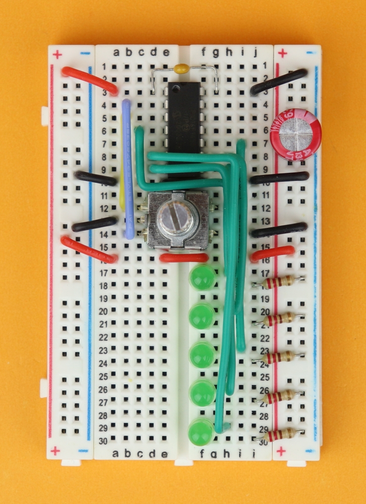
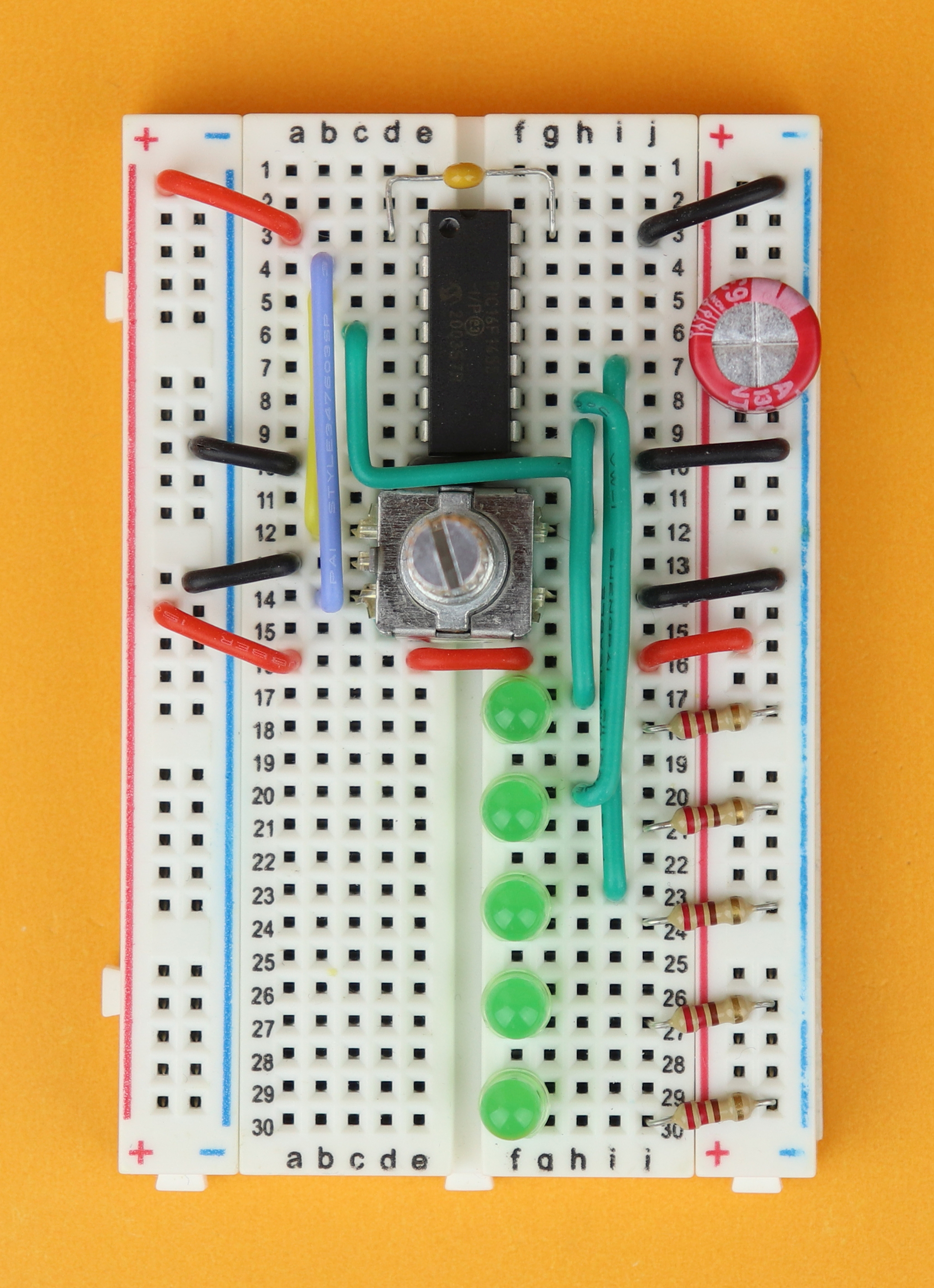
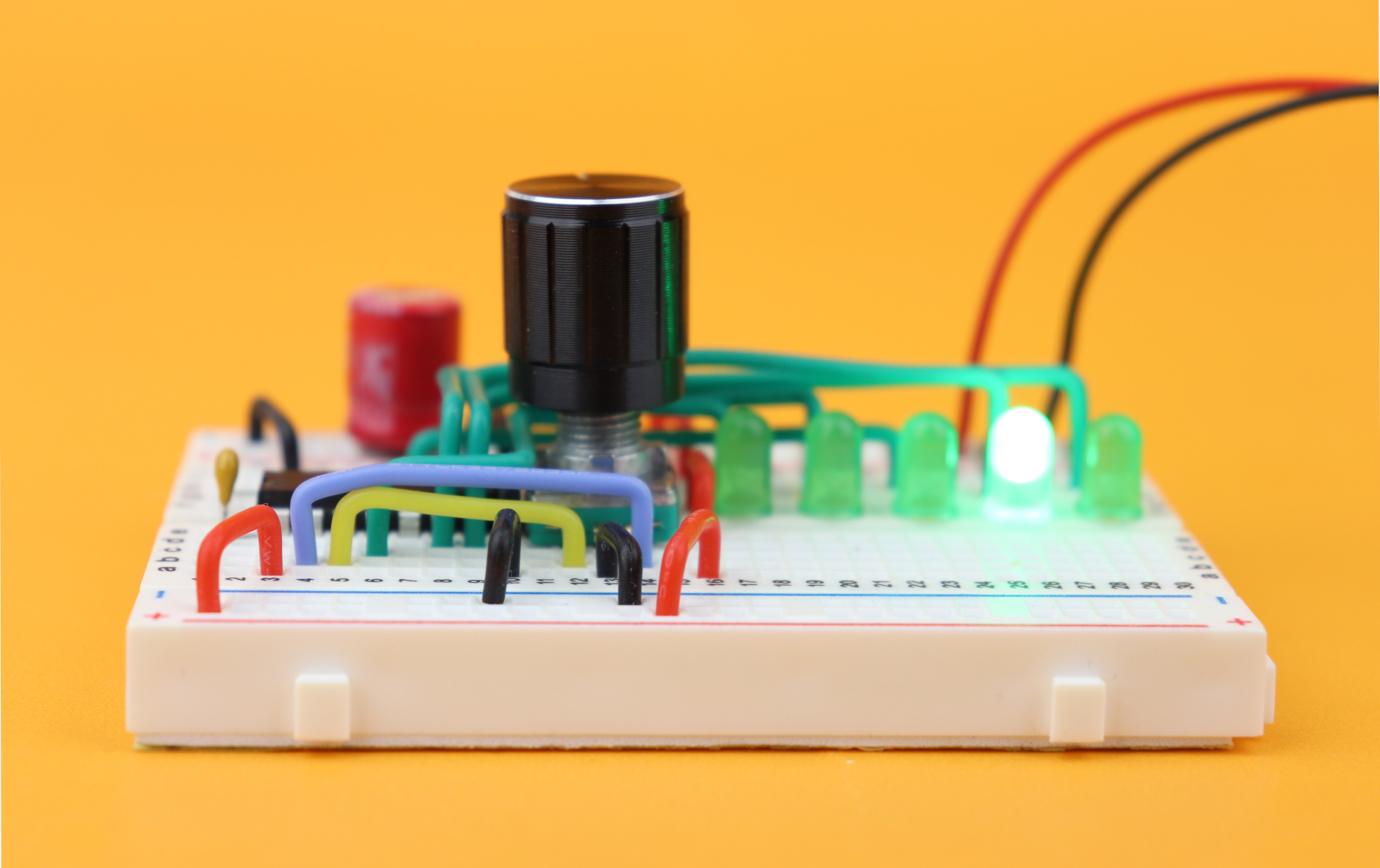
Incremental rotary encoders are mechanical devices that typically have five terminals. To see how they work, let's plug one into a breadboard in a simple test circuit:
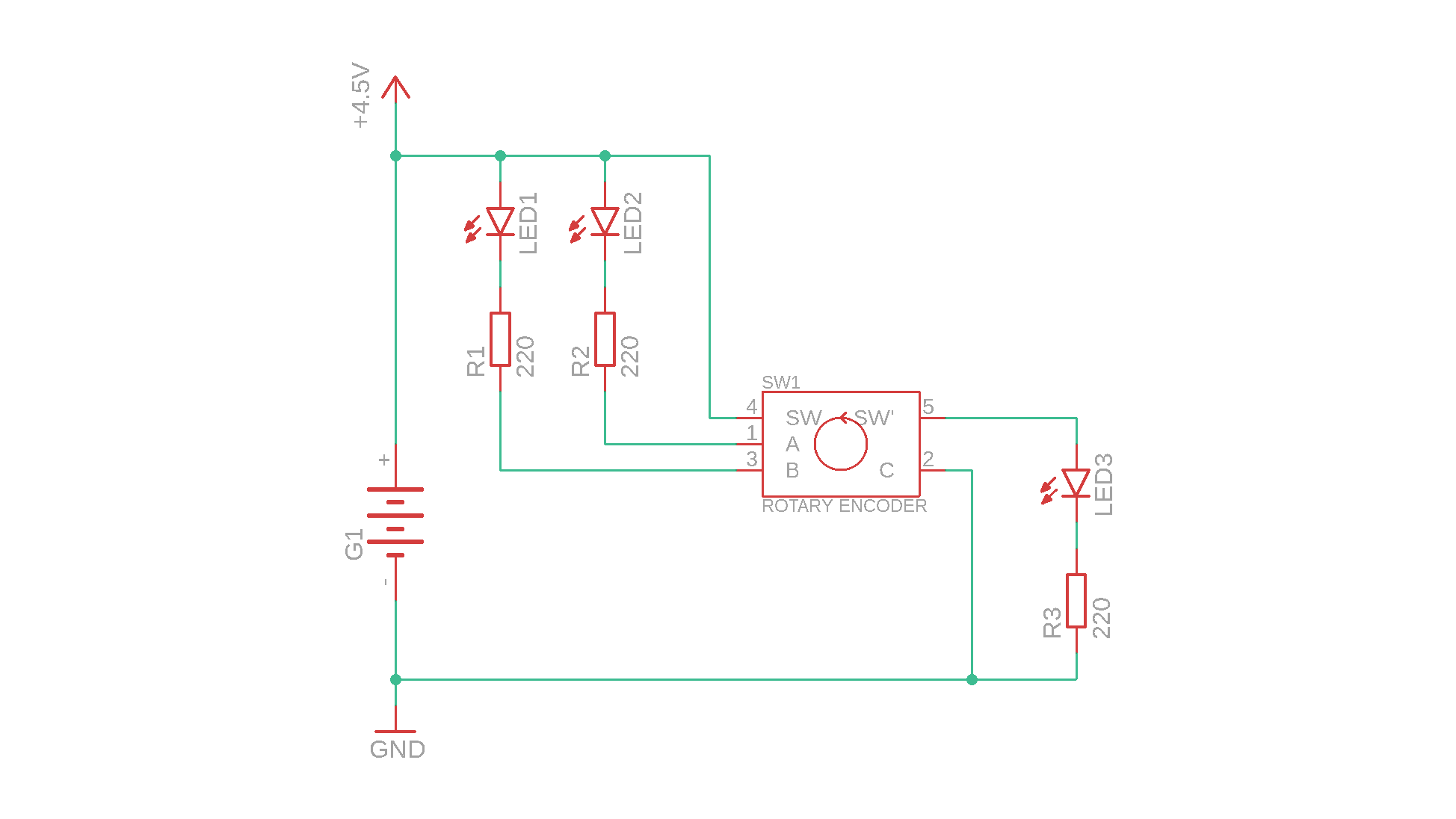

And now we can just turn the knob, and see what happens on the LEDs. First of all, if you press the rotary encoder, it makes the green LED light up, because it's only a pushbutton. So that part is pretty simple. But when we turn the encoder it gets more interesting:
Here is a more straightforward way to think about this pattern:
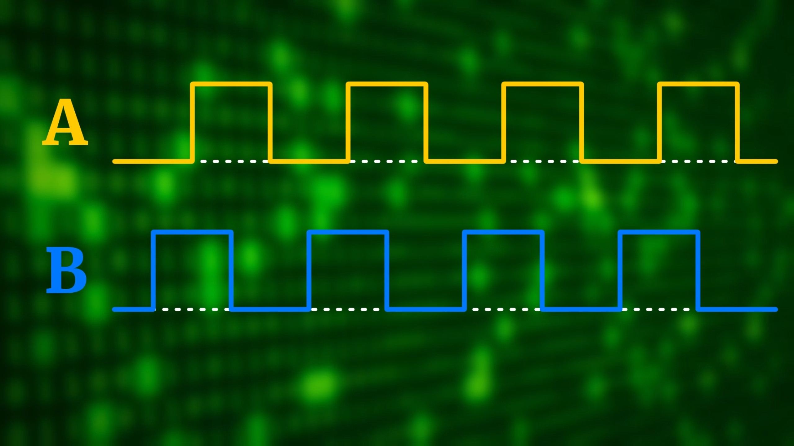
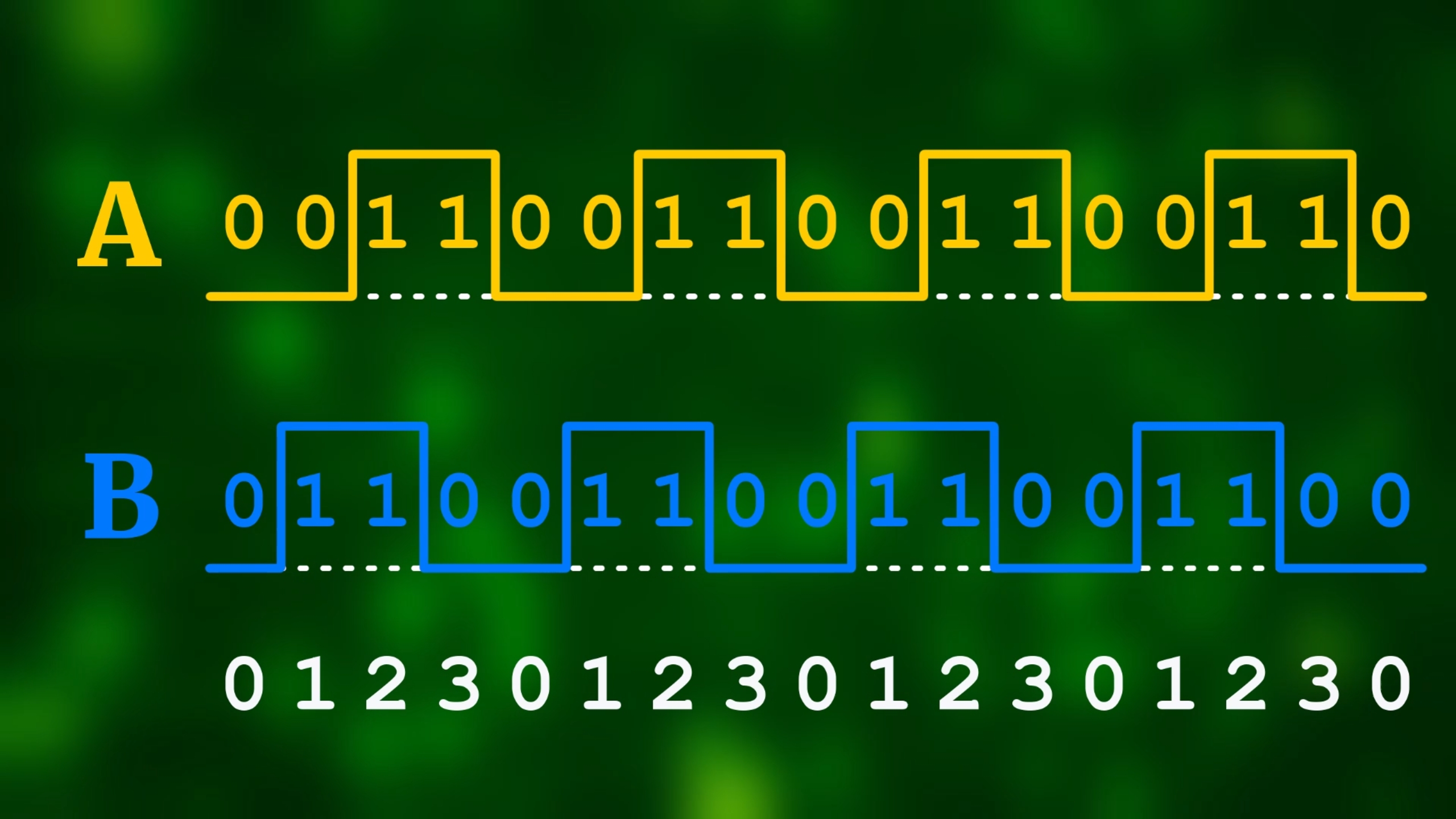
This pattern is called Gray code, and here is how it looks like as a logic signal:
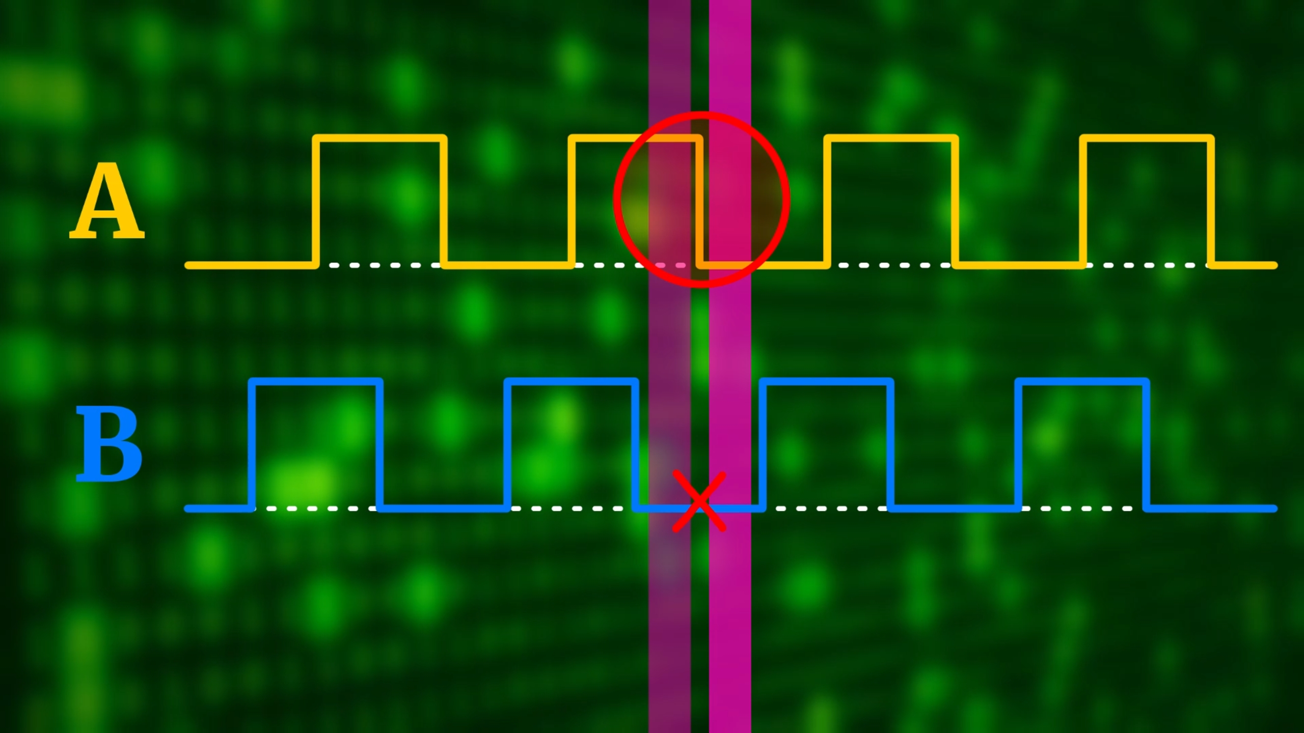
But at this point you probably want to ask: what makes Gray code so special? Why do we use this code, and not something else? Basically, if you look at the timing diagram, you see that from one step to the next one, only one pin changes (circled in red), and the other one stays the same (red cross):
And how do you find out the direction? All you need to do is compare the state before and after:
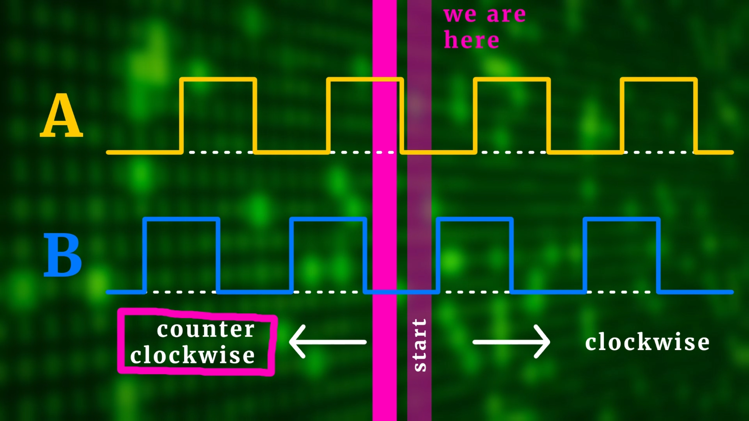
So, in this example, A and B were first both low, and afterwards B is still low, but A is now high. This means that we turned counter-clockwise. If instead A remained low, and B turned high, then we would have turned clockwise.
Imagine now that one of the contacts (say A) bounces:
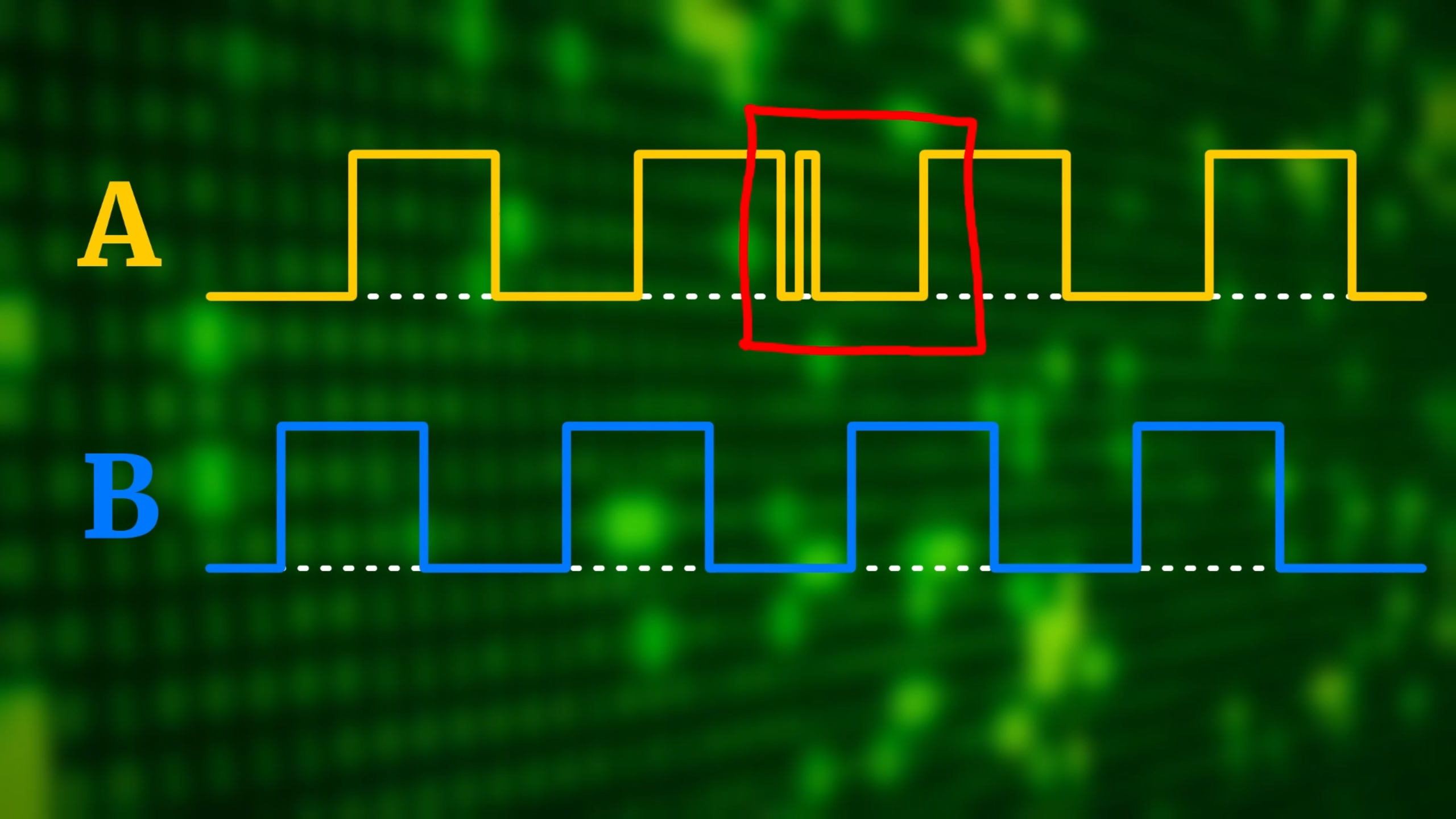
This can be a common mechanical problem. But you see: because in Gray code, from one step to the next one, only one pin ever changes (and never both), all that happens is that we count one additional step (by mistake) when something bounces. And, after the bouncing, we are back at where we started. This way Gray code is super reliable in practice, and we actually do not need to debounce the rotary encoder.
And last, I wanted to mention that many rotary encoders have little stops built in. The one we are using today goes through four steps, and then there is a little bump, and that's the sound you hear when you are turning one. Here is where the stops are located:
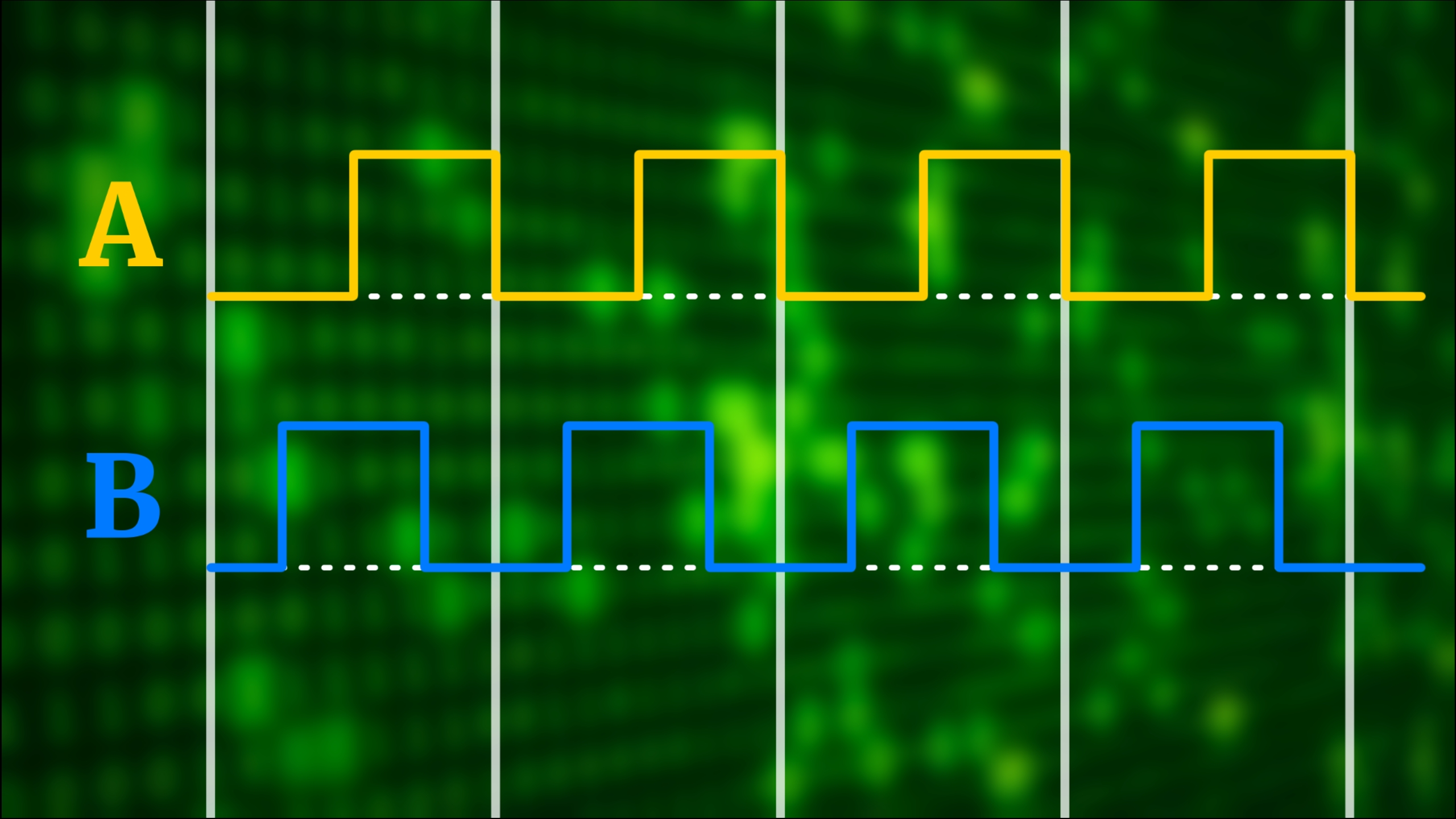
Let us keep that in mind for later, because often we want rotary encoders to only visibly increase a number (or anything else we adjust with them) when we feel such a bump, and not in between. Therefore (as we will see below) we will only count every fourth step in our program.
What makes rotary encoders work?
Okay, but now that we know how Gray code works, let us figure out how rotary encoders actually generate that code on the inside. When we take apart our simple rotary encoder that we will use in this tutorial, here is what we find on the inside:
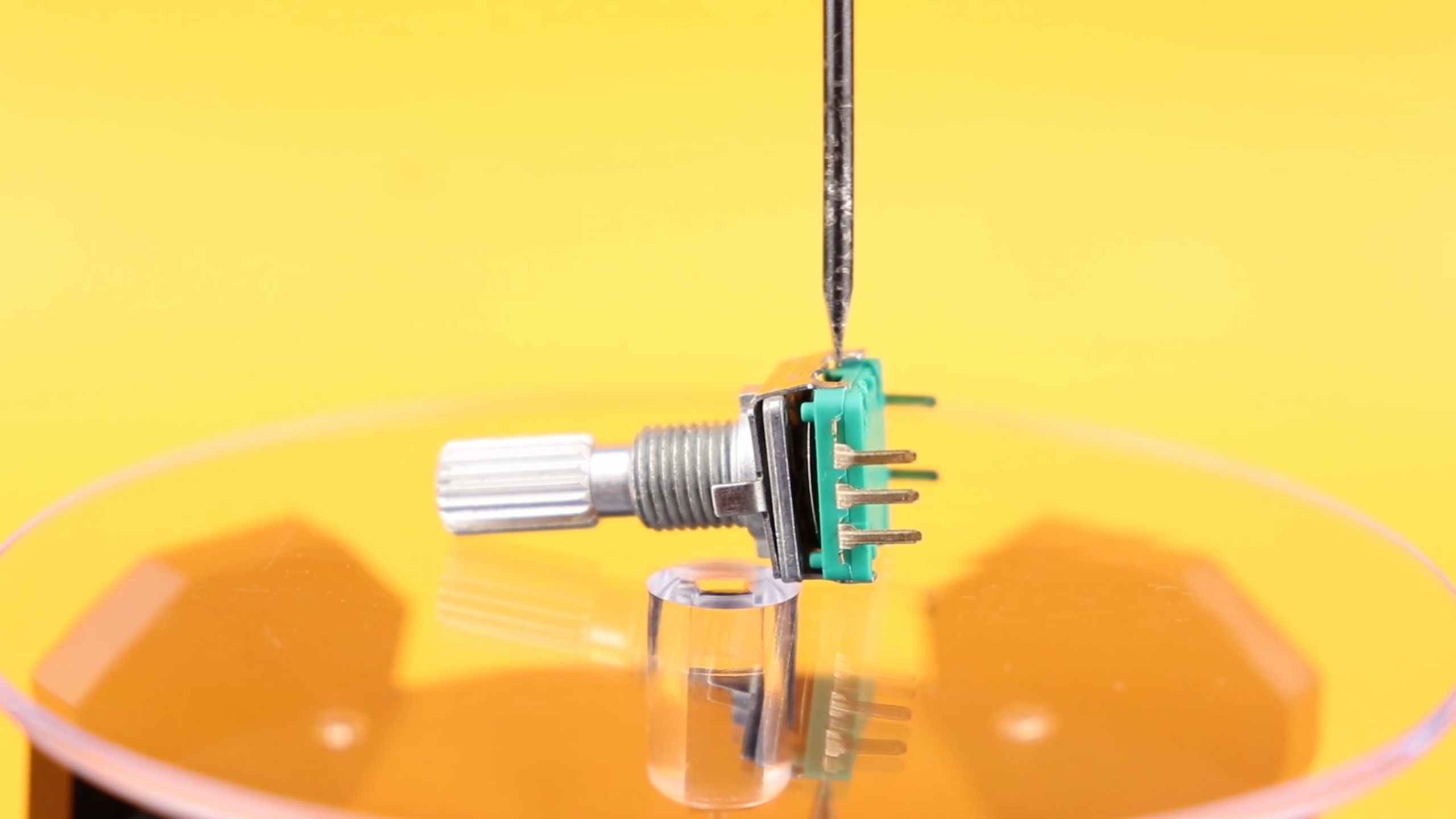
Usually, the upper aluminum part comes off after bending a few tabs out of the way. Taking off the base, you can see the contact wheel attached to the knob.

And here you can see the contact wheel again, next to the base:
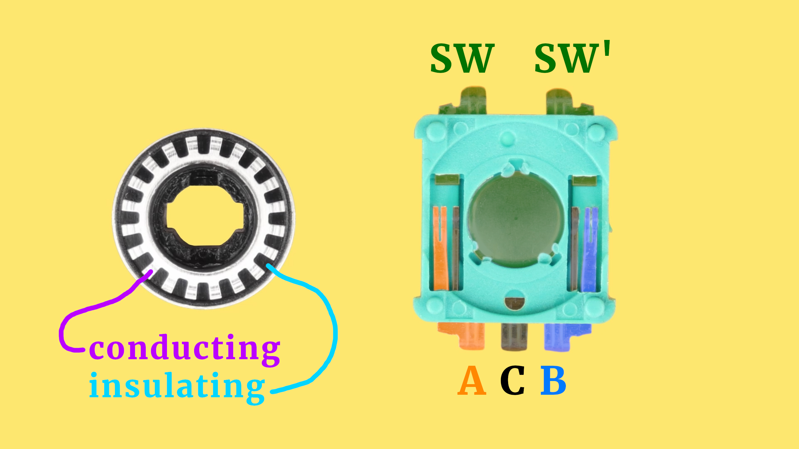
This deserves some explanation, so let's go through the different parts:
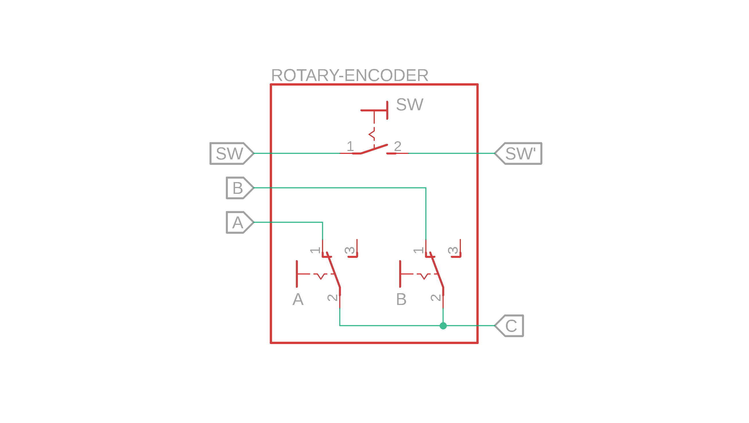
- Pushing down the knob pushes down the metal dome (the central green circular part), which then connects the two terminals SW and SW' at the top of the base, so: the pushbutton part is quite simple.
- If you look closely at the metal sliders on each side, you see that they each consist of three prongs. The outer ones go to pin A (orange) and pin B (blue), on either side, but the middle ones connect to the center pin C (black).
- So: if you place something conducting on top of these prongs, they act as simple switches, with a common contact C. Let's call them switch A and switch B. And this is where the contact wheel comes in! The shiny parts on the contact wheel are conducting, and the black parts are insulating.
- And when the contact wheel starts turning, it closes the two switches A and B in the exact pattern of Gray code! This is a bit hard to show with static images, so here is a short video:
Homemade rotary encoder
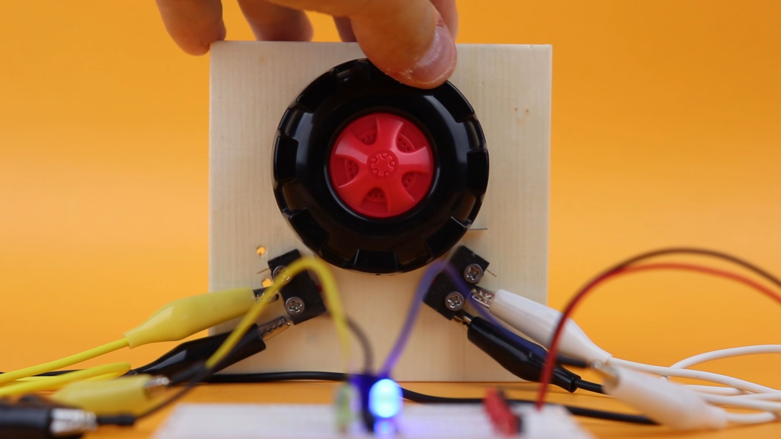
But this is all really quite small, and perhaps a bit hard to see, so I wanted to create something more tangible that letus us understand Gray code more practically. So: I built a larger rotary encoder, using limit switches and a toy car wheel!

And, as you can see, this type of wheel has exactly the right kind of repeating pattern that we can use for a rotary encoder. All we need to do is combine it with some limit switches:
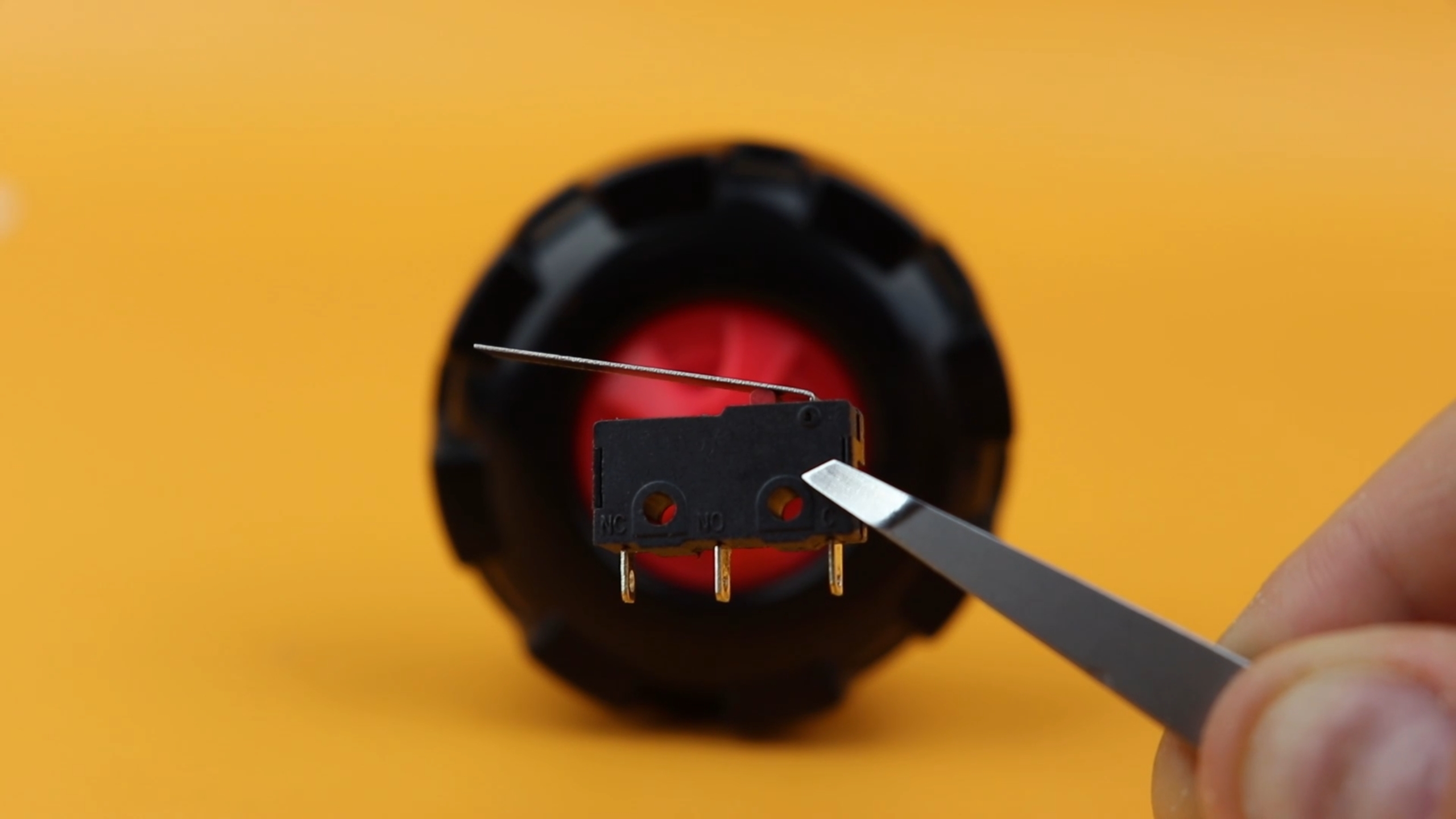

The idea is to arrange two limit switches so that the wheel's periodic shape engages the two switches in the Gray code pattern. This takes some tweaking, but after a few attempts I got it to working:
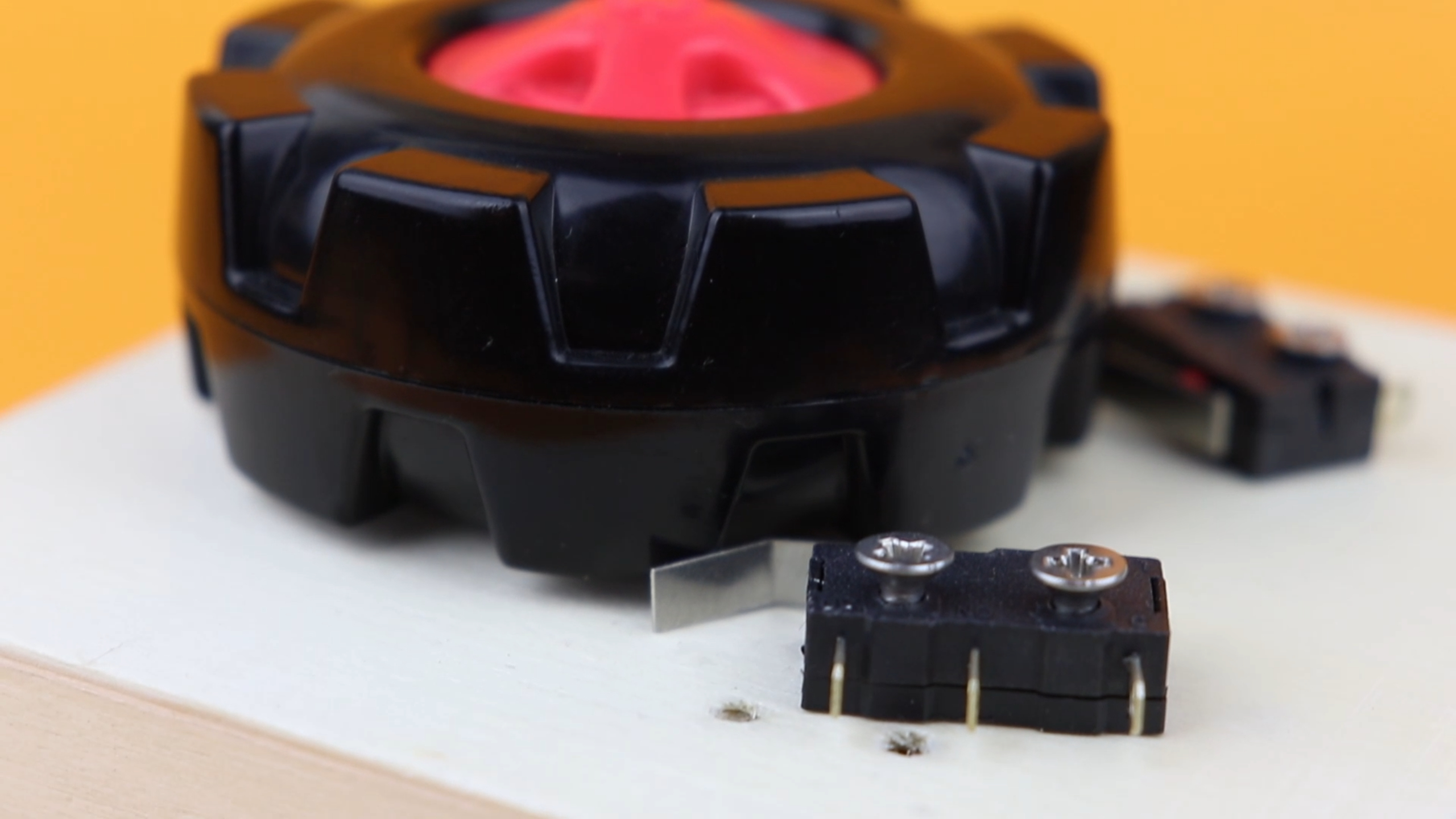
The switches have to be arranged accurately for this to work, and their position depends a lot on the geometry of the wheel you end up using. I didn't get it right the first time around, as you can see by the two drilled holes that I didn't end up using:
So, a rotary encoder is basically two switches that are turned ON and OFF in a funny pattern (Gray code):
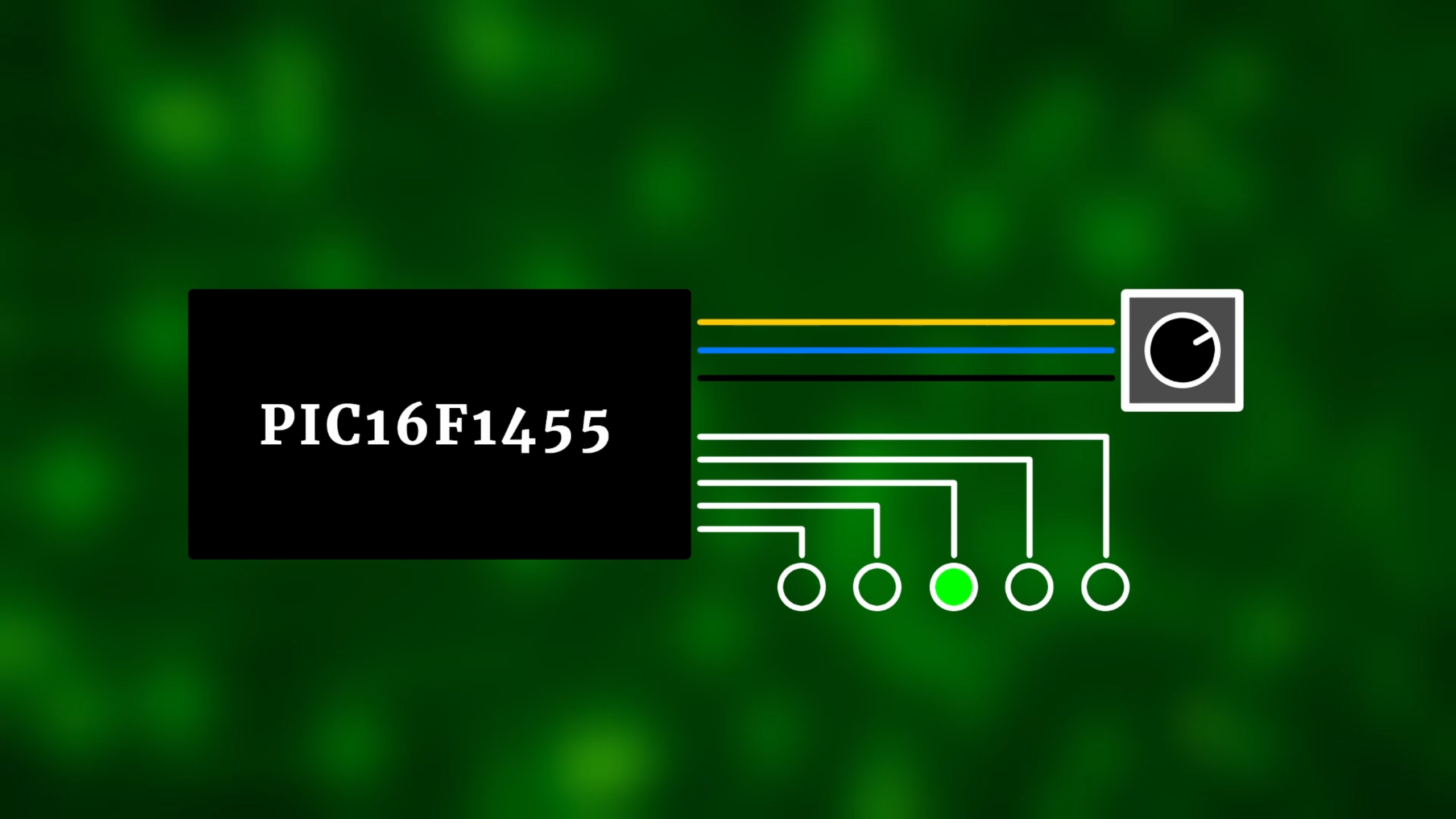
Now, for the rest of this tutorial we want to learn how to read out this rotary encoder using a microcontroller, and this is one way to do it:
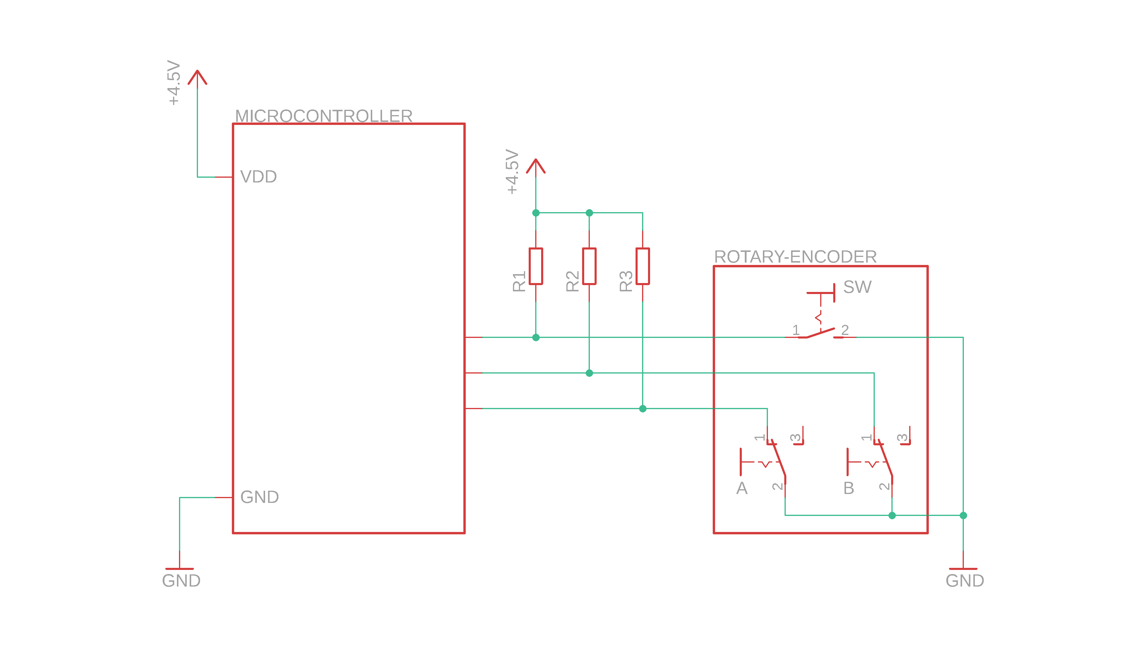
The idea is to connect one side of the switches (the C terminal, and one side of the pushbutton) to ground, and to connect the other side to inputs of the microcontroller. Then, we connect each input to VDD with pull-up resistors R1–R3 that make sure that each input has a well-defined logic level (high level) when the switch is open. Values of around 5-10kΩ would be a good choice for such resistors.
And, actually, we don't need to physically put these resistors into our circuit, because many microcontrollers (including the PIC16F1455 that we will be using today) have built-in pull-up resistors:
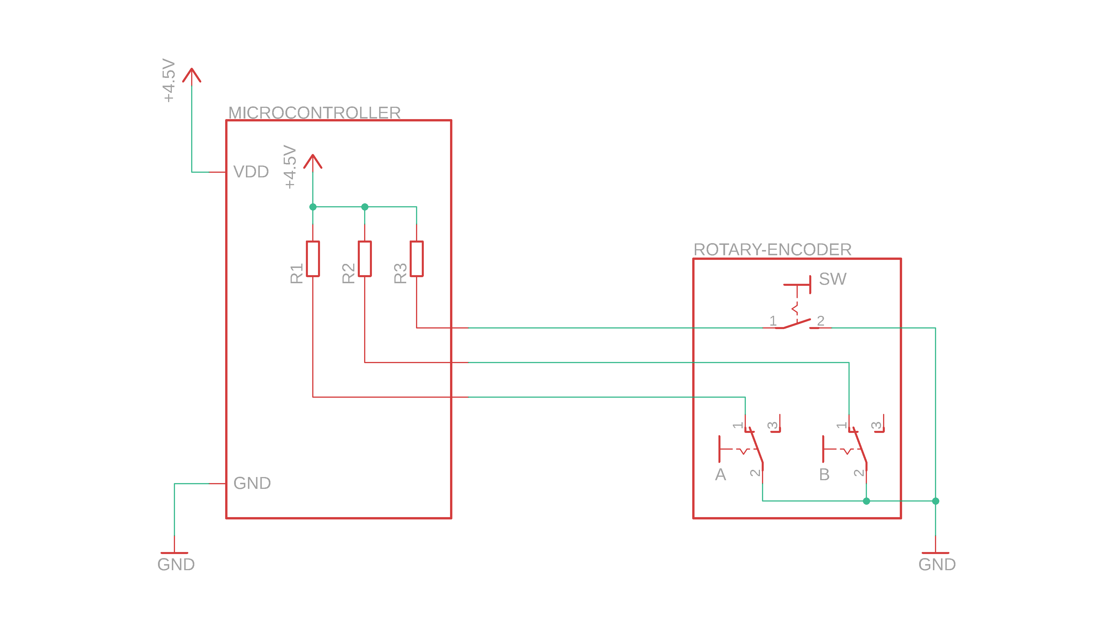
And now we are far enough in the tutorial that we can finalize our idea for a schematic!
What you need
But before we talk about the schematic, in case you want to build this circuit for yourself, too, then here is what you need:
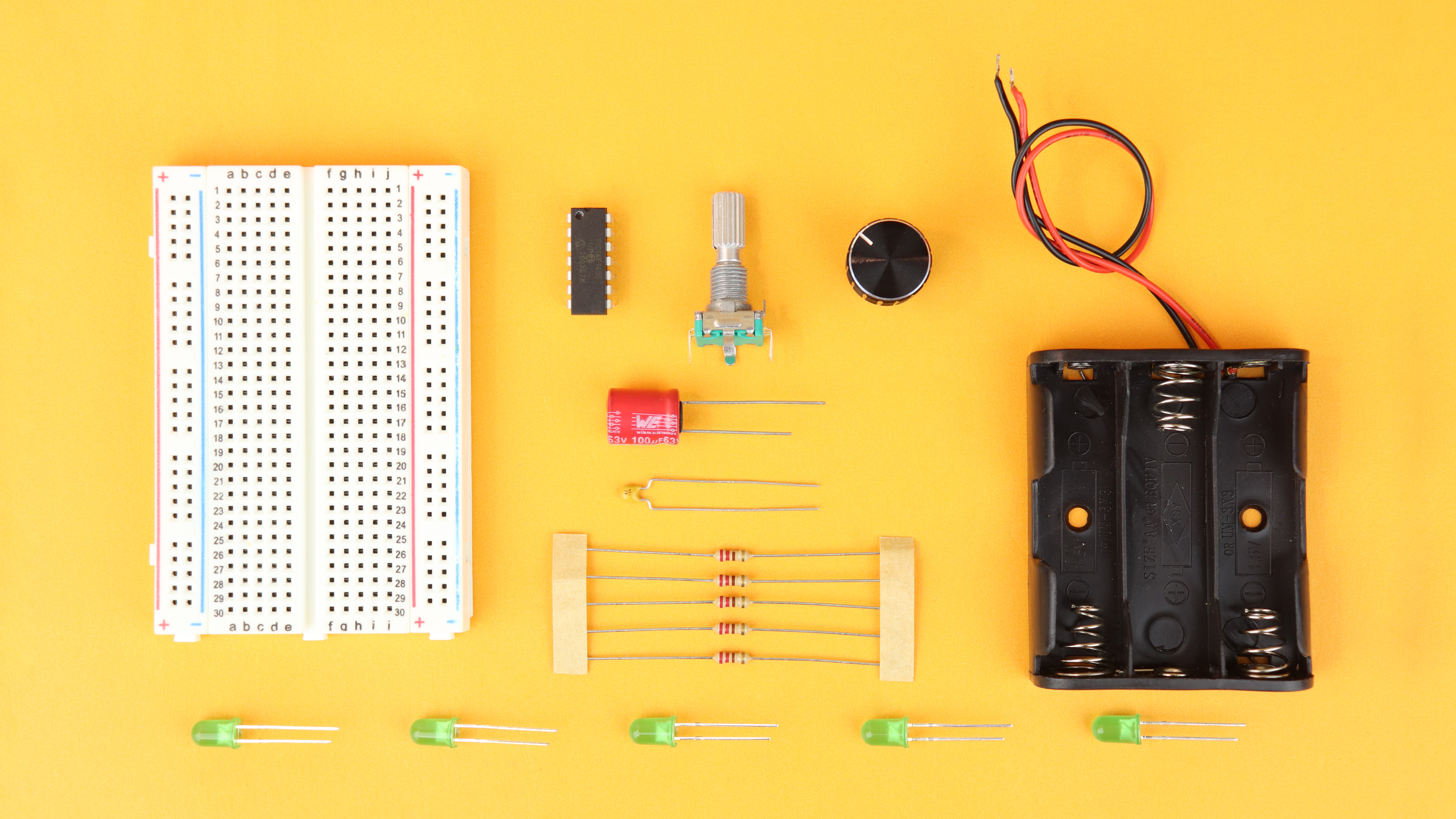
As always, there is a detailed list of components in the components box. Let's go through the components:
- Of course we need a rotary encoder, and this tutorial focuses on an incremental rotary encoder with three terminals ABC as well as a built-in pushbutton.
- We will use the PIC16F1455 to read out the rotary encoder, but you can use any other microcontroller you like, the idea of decoding the signal is the same.
- Other than that we need some capacitors (for stability), and some LEDs so that we can visualize in which direction we turn the rotary encoder. For this tutorial we will use five simple LEDs for that.
Other than that you will also need the PICkit3.
Schematic
Okay, and here it is, our schematic to read out a rotary encoder with our microcontroller:

So let us go through the main parts step by step.
- The PIC16F1455 microcontroller is the brain of the operation, and usual we run it off of a 4.5V battery pack with a 100μF bulk capacitor (C1) and a 100nF bypass capacitor (C2) for stability.
- We connect the common pin of the rotary encoder to ground, and its two terminals A and B to inputs of the PIC16F1455; and we do the same with the internal pushbutton.
- Then we also have five LEDs that we will use to visualize the motion of the rotary encoder, and they are connected to outputs of the PIC16F1455 with 220Ω current-limiting resistors.
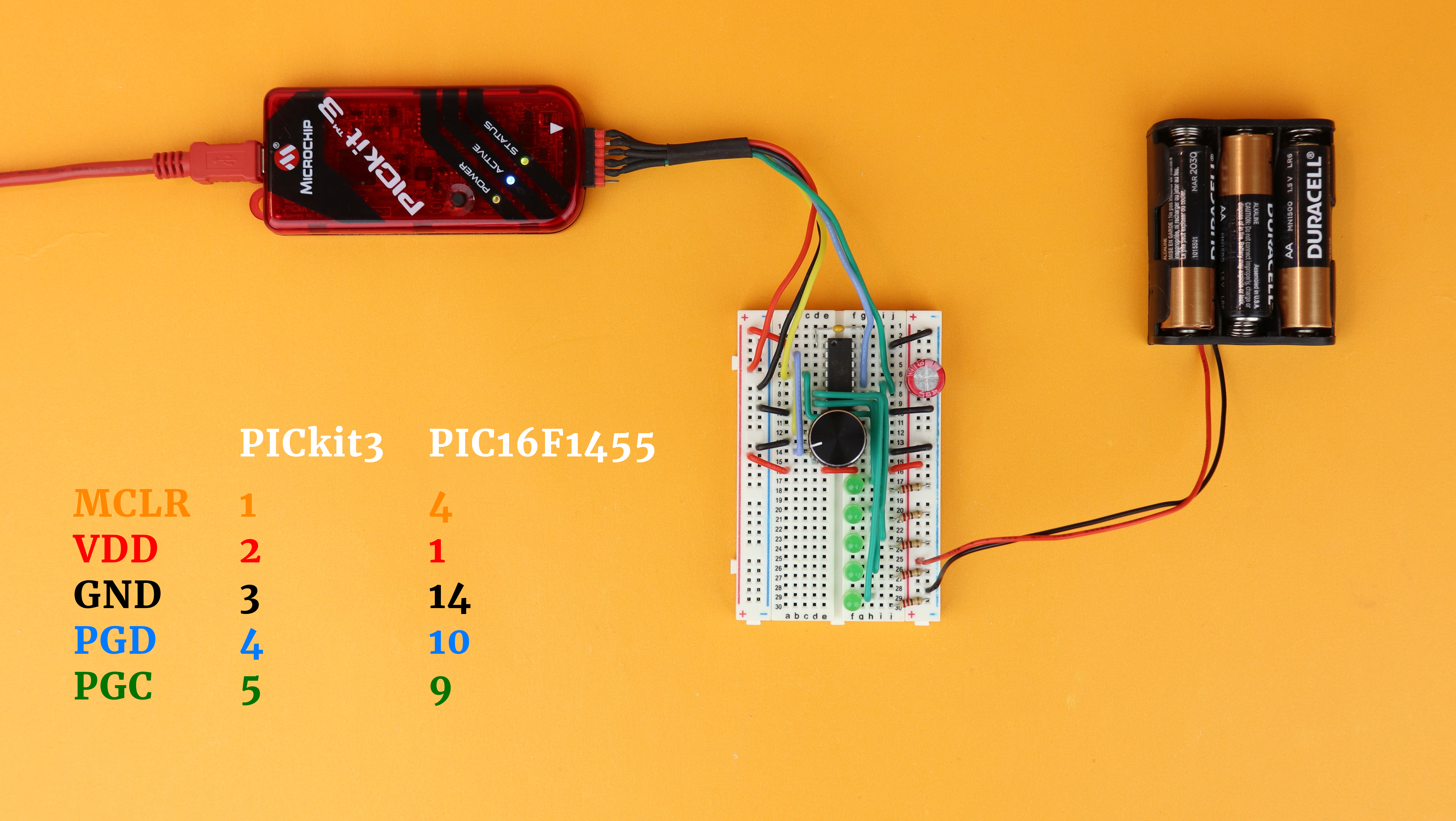
- The symbol at the top is the PICkit3 that we need to transfer the .hex-file onto the microcontroller, and the PICkit3 connected to the PIC16F1455 via the five wires VDD, GND, Master Clear, Program Data, and Program Clock, just as usual.
And that's it, pretty simple! Of course, in a real-life application you would do something more interesting with a rotary encoder than driving five LEDs, but I wanted to keep this tutorial as simple as possible, which is why we only use five LEDs. But you could of course use different display modules, like the TLC5916 or the MAX7219 LED drivers, to create more interesting projects. Or you could even use a rotary encoder as an input device for our real-time clock or the analog clock, there are so many possibilities!
Building the circuit
Now of course we have to program the functionality into the microcontroller, but for now: let's get this circuit built on our breadboard!
-
-
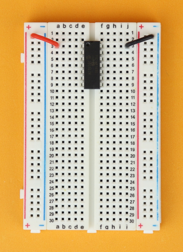
Step 1
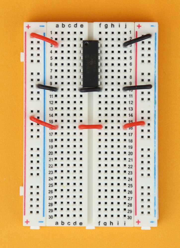
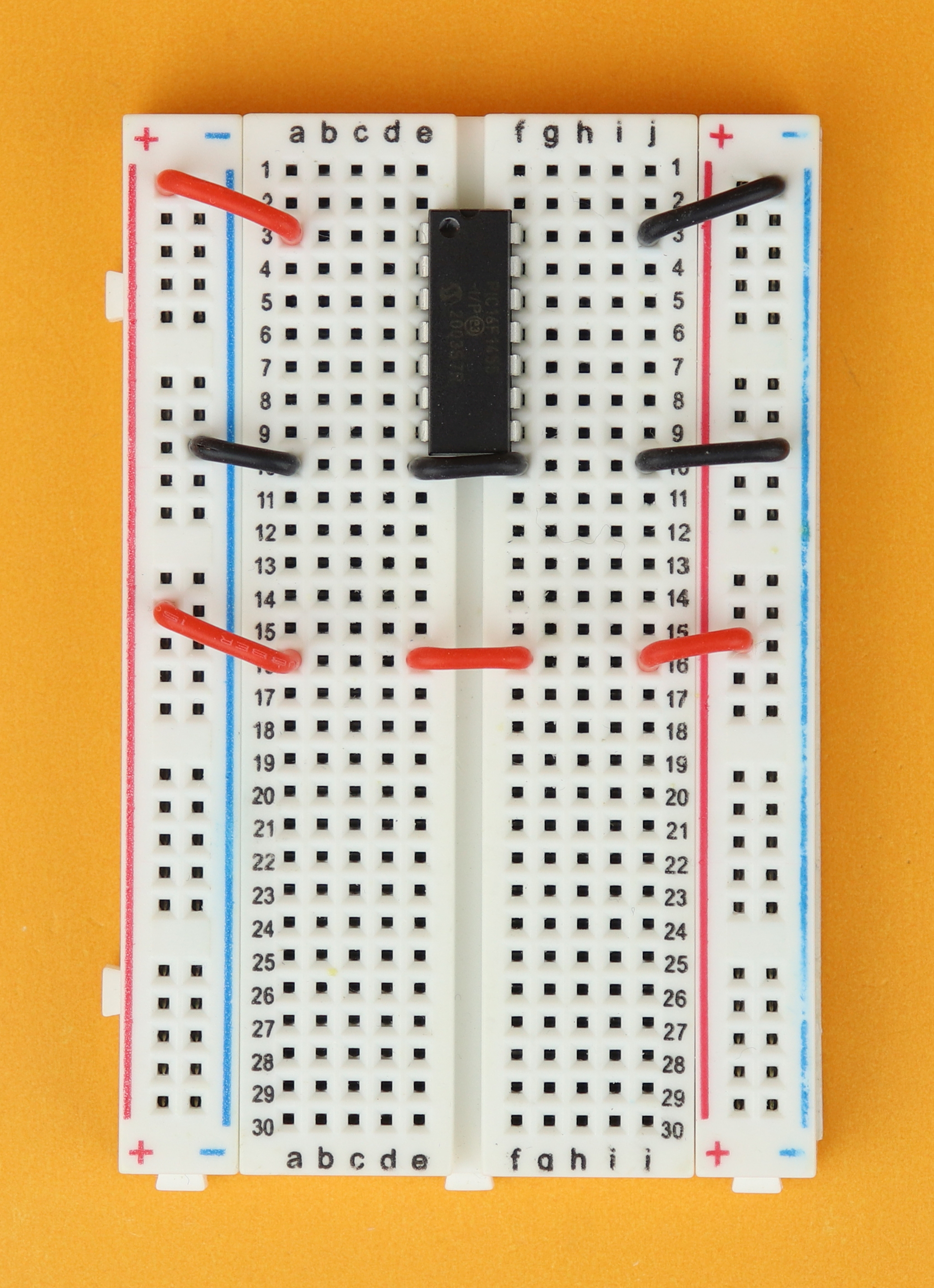
Place the 400-pin breadboard in front of you, and make sure row 1 is at the top. Insert the PIC16F1455 in row 3 and connect it to power at pins 1 and 14.
-
-
Step 2
Next, make sure that the power rails on either side are connected in parallel.
-
-
Step 3
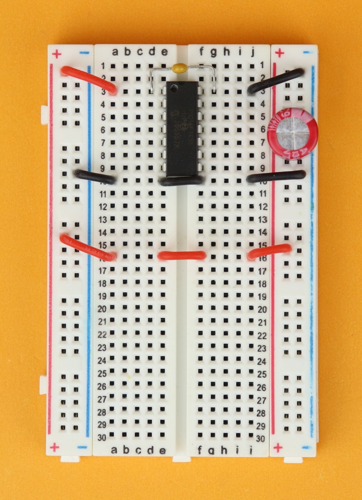
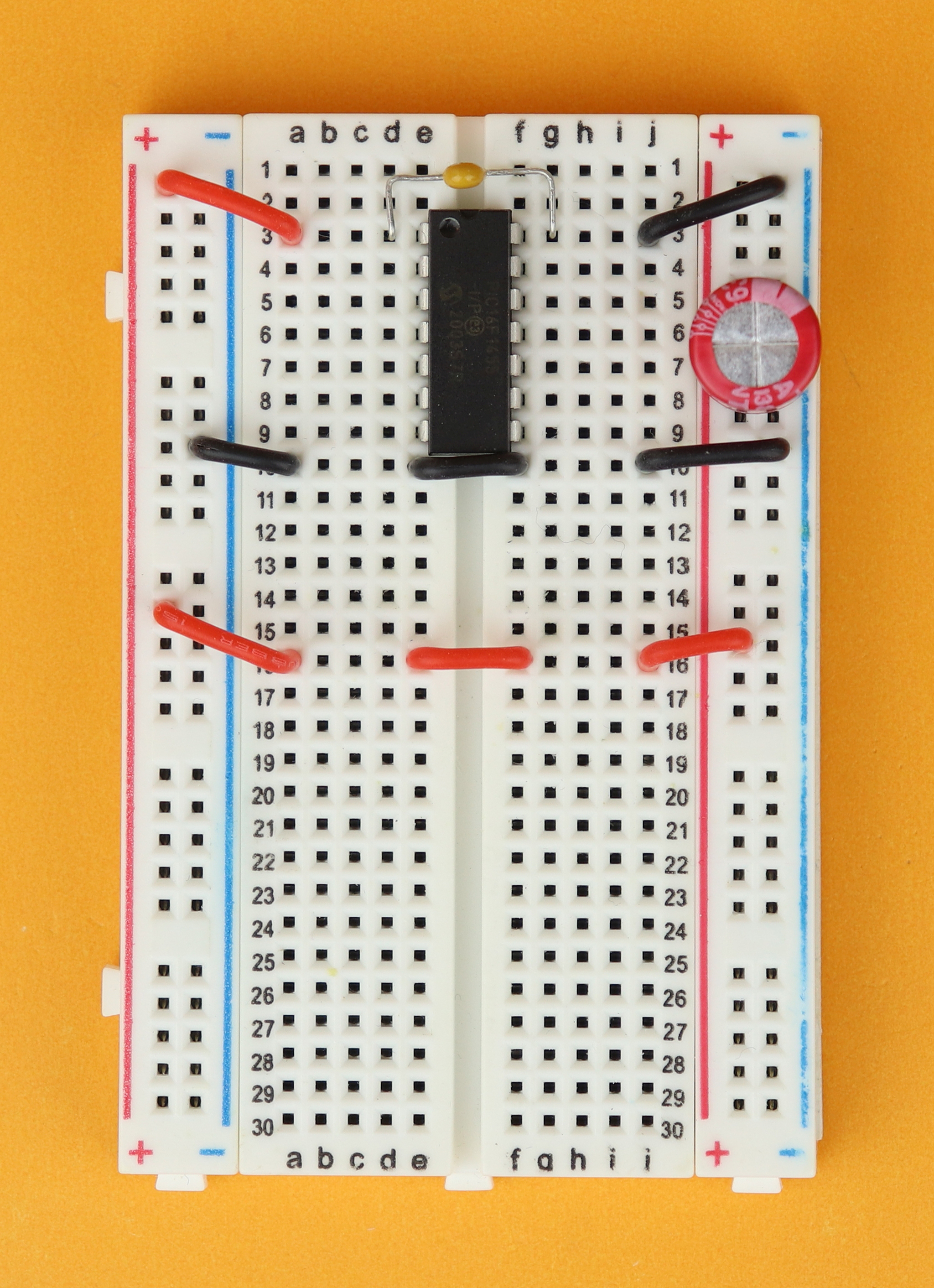
Insert the bypass capacitor C2 between pins 1 and 14 of the PIC16F1455, and the chunky bulk capacitor C1 in the power rail, making sure that the negative terminal is connected to the blue ground rail.
-
-
Step 4
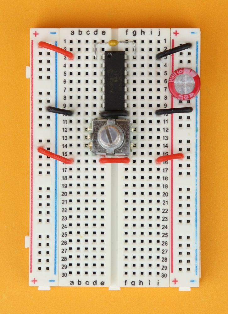
Next, place the rotary encoder in row 12, with the three ABC terminals facing to the left, and the two pushbutton terminals to the right.
-
-
Step 4b
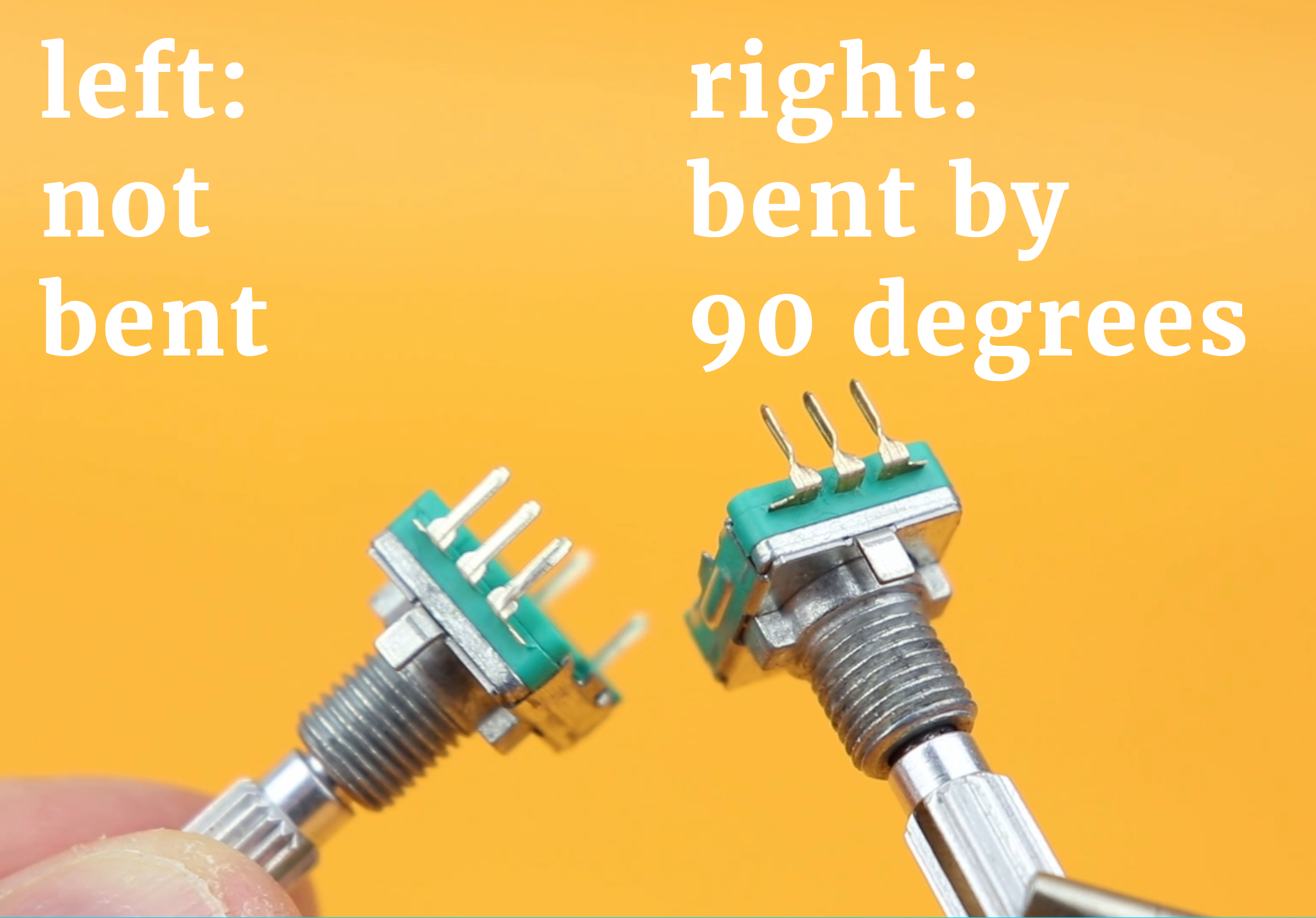
I find that sometimes these rotary encoders don't fit snugly into breadboards, and actually end up jumping out all the time because of the way the leads are bent. But if you twist the leads by 90 degrees with some pliers before inserting the encoder in the breadboard they go in a lot more easily.
-

-
Step 5
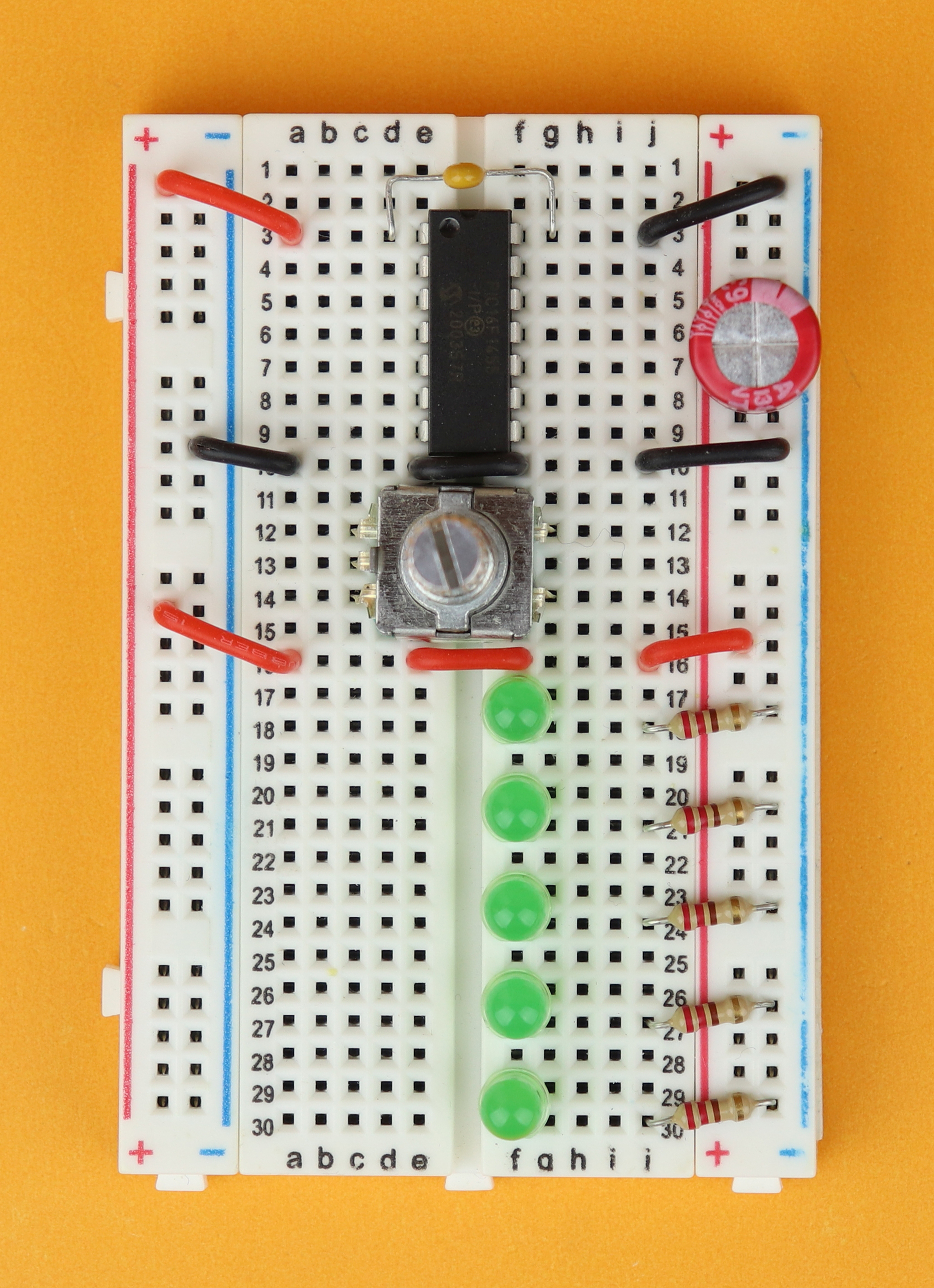
After this brief intermezzo, it's time to insert the LEDs, with the anodes facing up, in rows 17, 20, 23, 26, and 29; their cathodes are then connected to the ground rail with their 220Ω current-limiting resistors in rows 18, 21, 24, 27, and 30.
-

-
Step 6
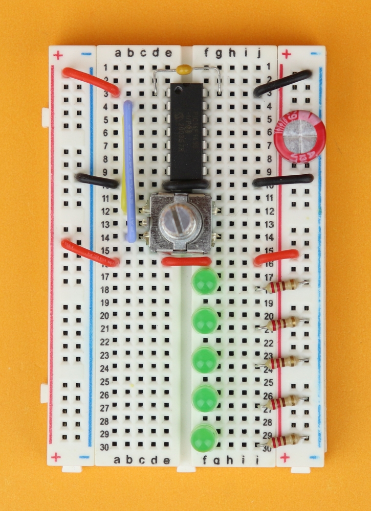
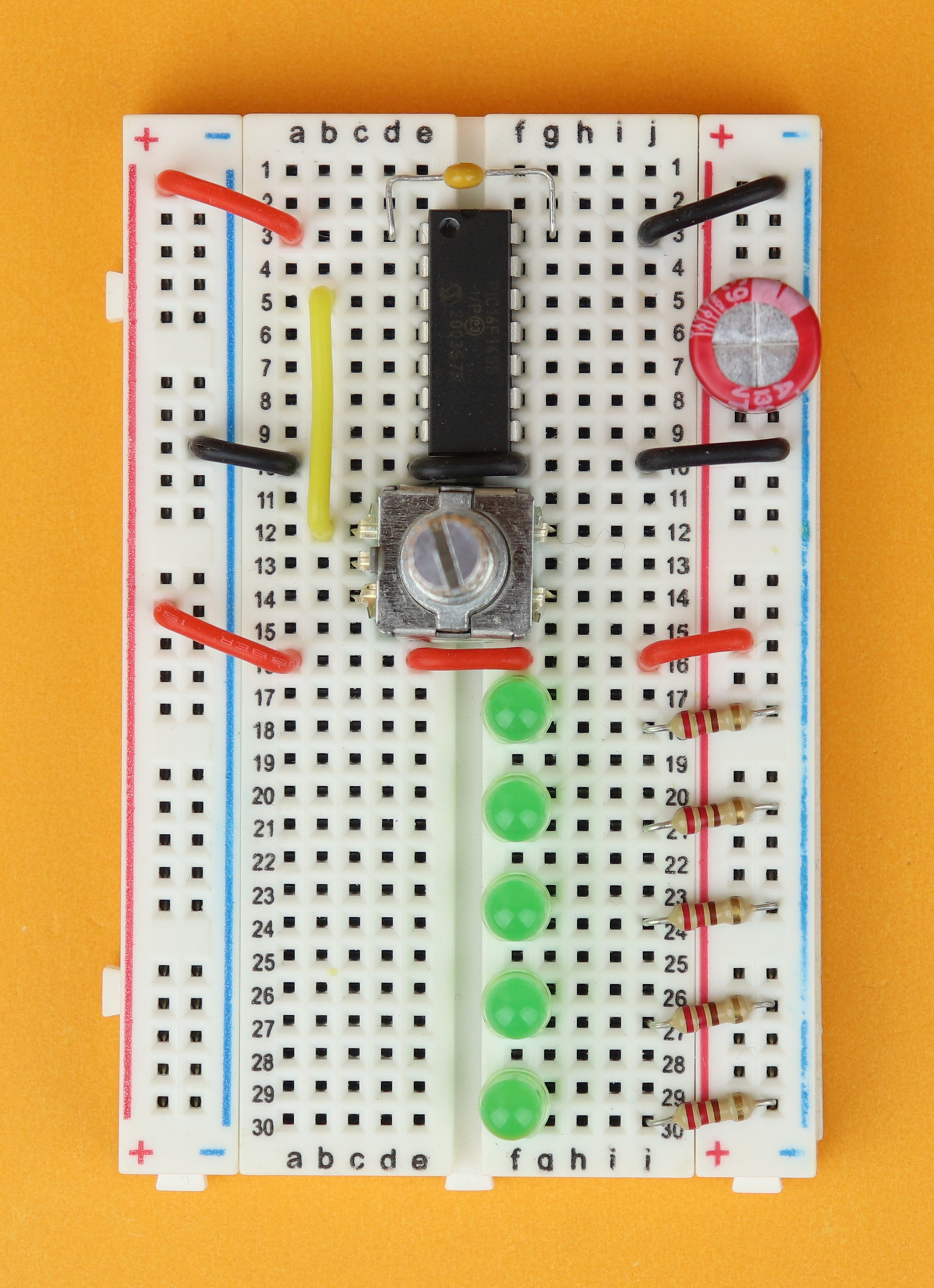
Now, let's connect our rotary encoder. Pin A of the rotary encoder goes to pin 3 of the PIC16F1455.
-
-
Step 7
Pin B of the rotary encoder goes to pin 2 of the PIC16F1455.
-
-
Step 8
Pin C goes of the rotary encoder goes to ground.
-
-
Step 9
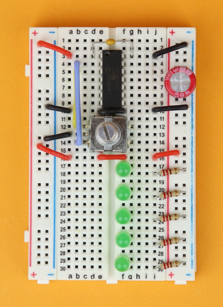
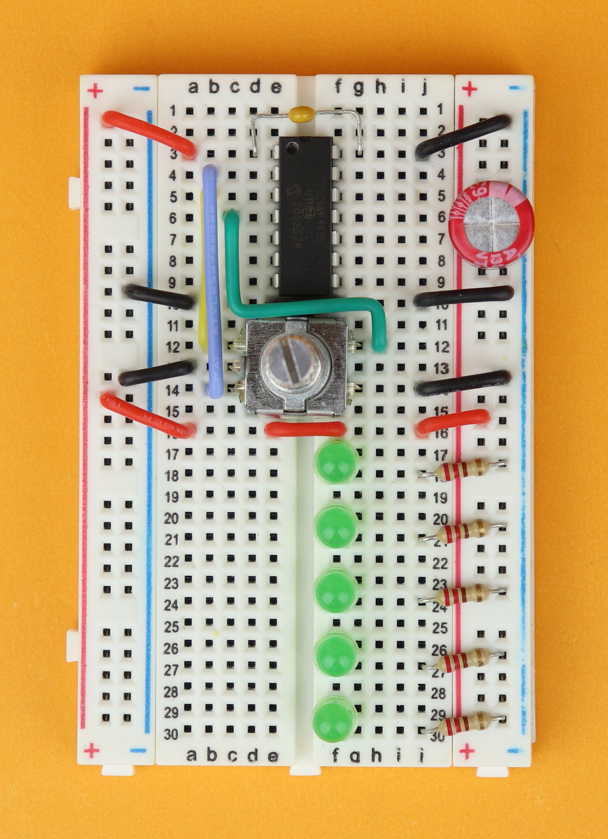
On the other side, connect one of the rotary encoder's button terminals to pin 4 of the PIC16F1455. And the other pushbutton terminal is connected to ground. You can do that either way around, it doesn't matter because it's just a pushbutton :)
-

-
Step 10
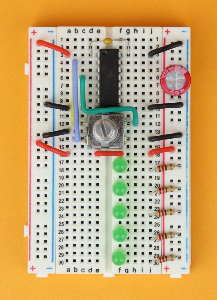
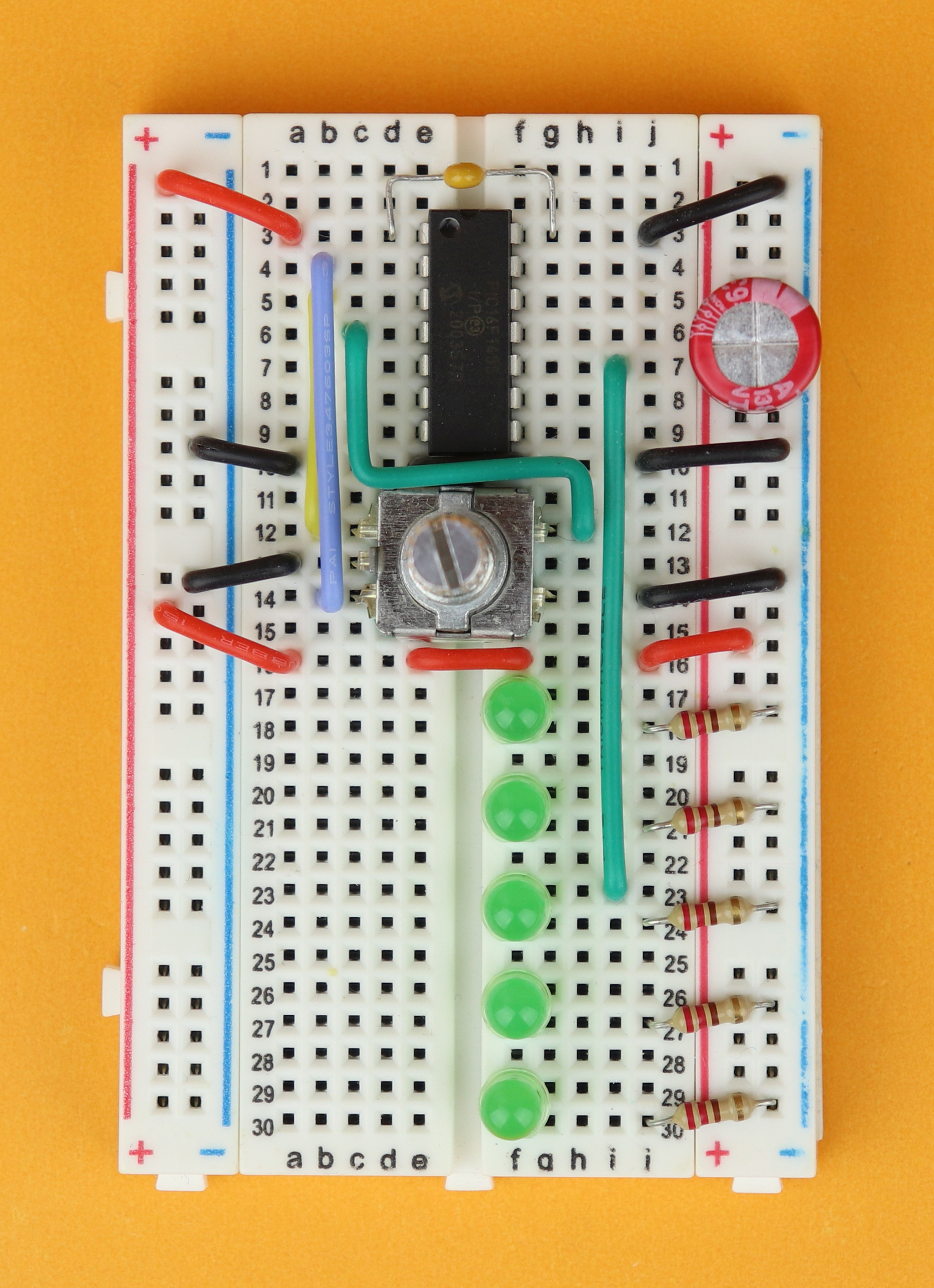
And last, it's time for the LED anodes. LED 3 (row 23) goes to pin 10 of the PIC16F1455.
-

-
Step 11
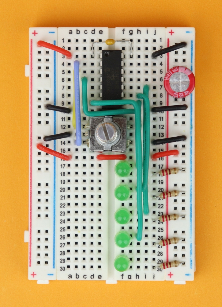
LED 1 (row 17) goes to pin 8 of the PIC16F1455.
-

-
Step 12
LED 2 (row 20) goes to pin 9 of the PIC16F1455.
-
-
Step 13
LED 4 (row 26) goes to pin 7 of the PIC16F1455.
-
-
Step 14
And last, LED 5 (row 29) goes to pin 6 of the PIC16F1455.
-
-
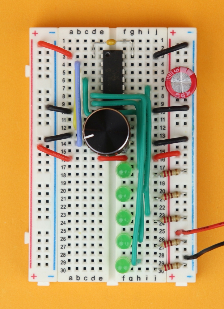
Step 15
Now you can place the aluminum knob on the rotary encoder, and connect the 4.5V battery pack to the power rail (red wire to the red VDD rail, and the black ground wire to the blue GND rail).


And, finally, it's time to connect the PICkit3. Here is how this looks like:
After that, don't forget to plug the USB end into your computer, and now we are ready to program our controller!
If you don't care so much about programming and just want to get it working, feel free to jump ahead to the next section where we will flash the .hex-file onto the controller.
Software
So, before we delve into the depths of our source code, let's think for as second what we want our program to do. There are basically two key components: the rotary encoder and the LEDs.
At the beginning, the leftmost LED is turned on, and when we turn the rotary encoder, we move the glowing LED around. And when we push the internal pushbutton, the LED pattern gets inverted, just for fun.
Internally, in the program, this is not so difficult to achieve. We have five LEDs, and our rotary encoder does four steps for each tactile bump, so we need to cover 20 different scenarios (four steps for each LED). When we define a variable v, it will take values from 0 to 19. And by dividing the variable by 4, we will know what LED is supposed to be turned ON.
So we basically have reduced the problem to one simple thing: how can we figure out if the rotary encoder has been turned clockwise or counter-clockwise? The easiest way to find out is to first convert Gray code into normal binary numbers (clockwise goes to the right, counter-clockwise goes to the left):
When we now measure the state of the rotary encoder, it will be a number from 0 to 3. Now: whenever the program detects that the old state is different from the news state (that is: somebody turned the rotary encoder!), we can calculate the difference between the old number and the new number.
Here you can see examples for a clockwise rotation (and the difference can only ever be -1 or 3):
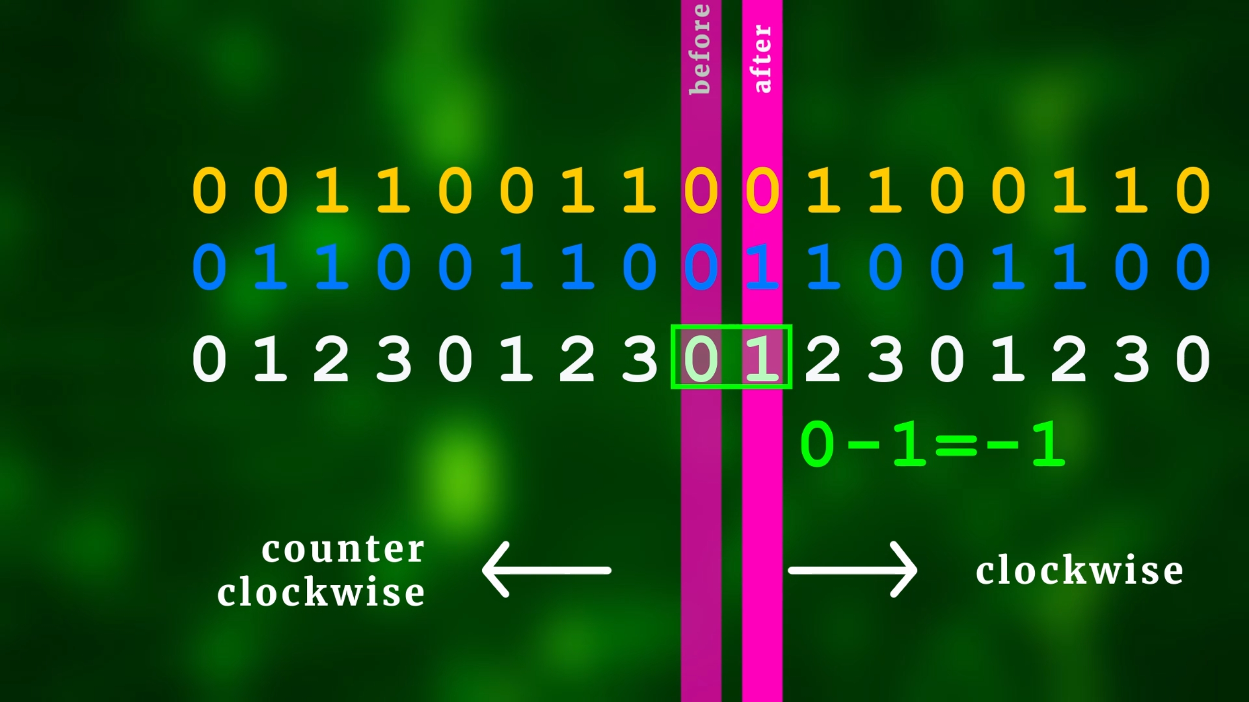
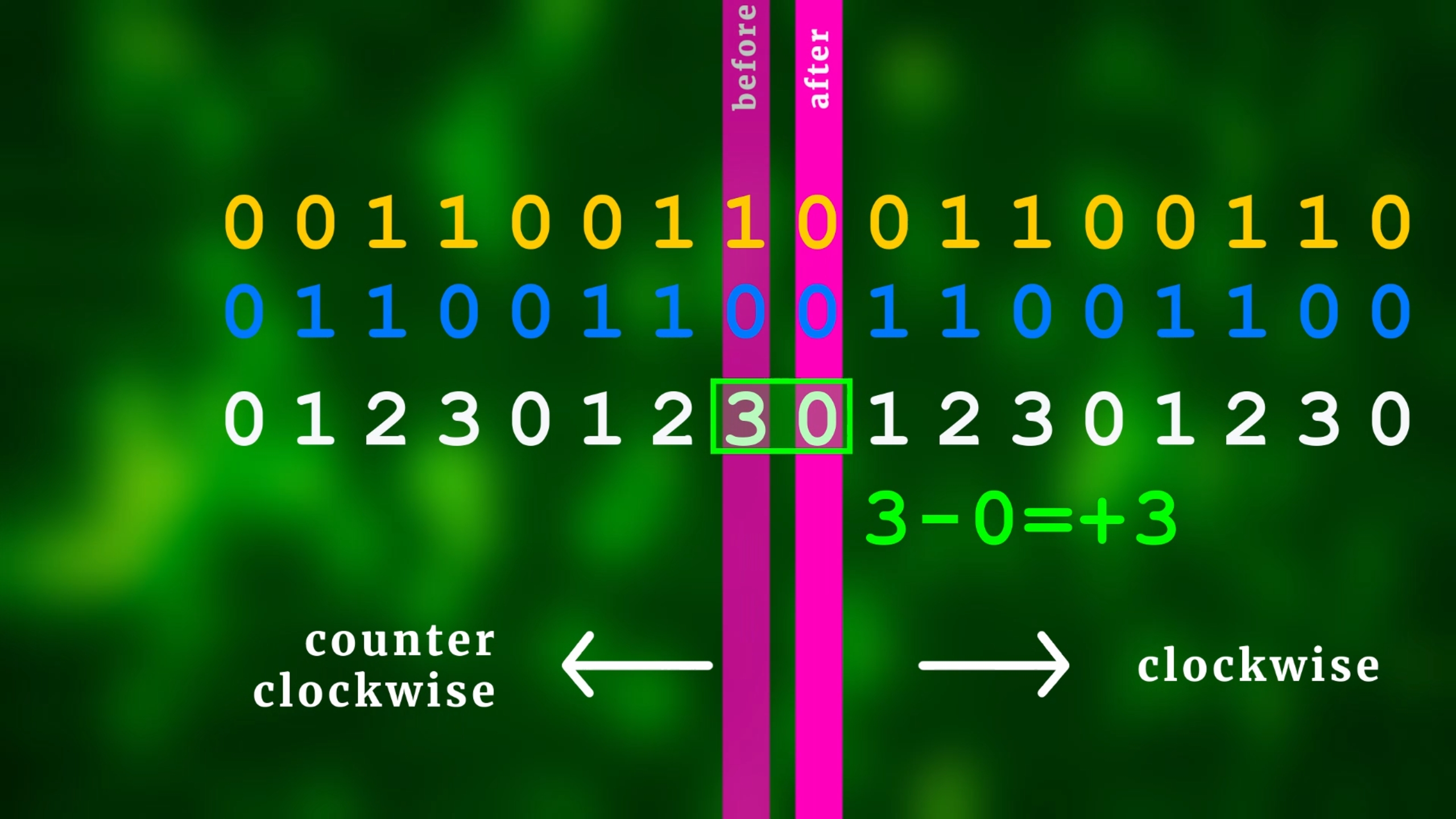
And this is how it looks like for the counter-clockwise rotation (where the difference can only ever be 1 or -3):
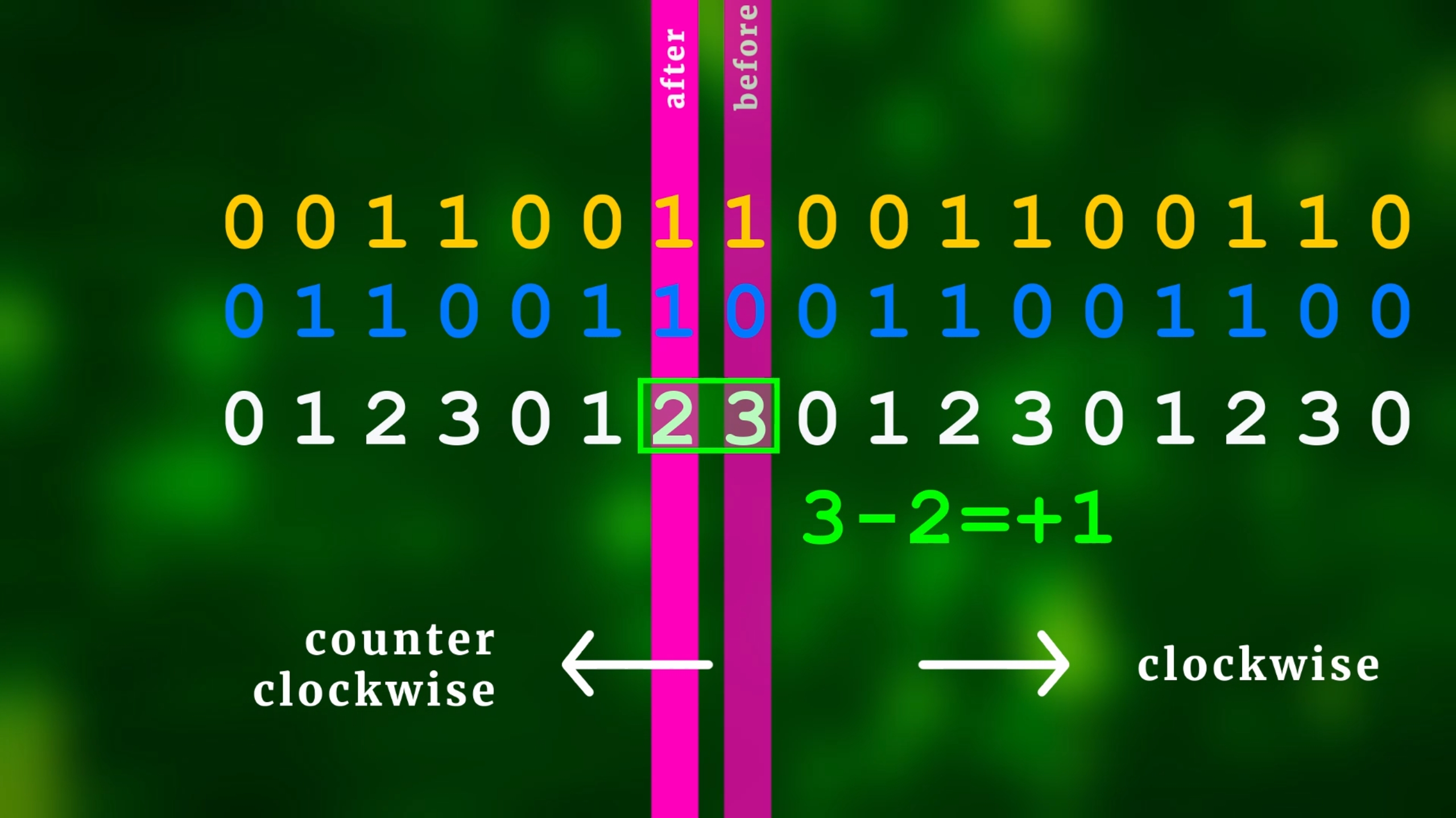
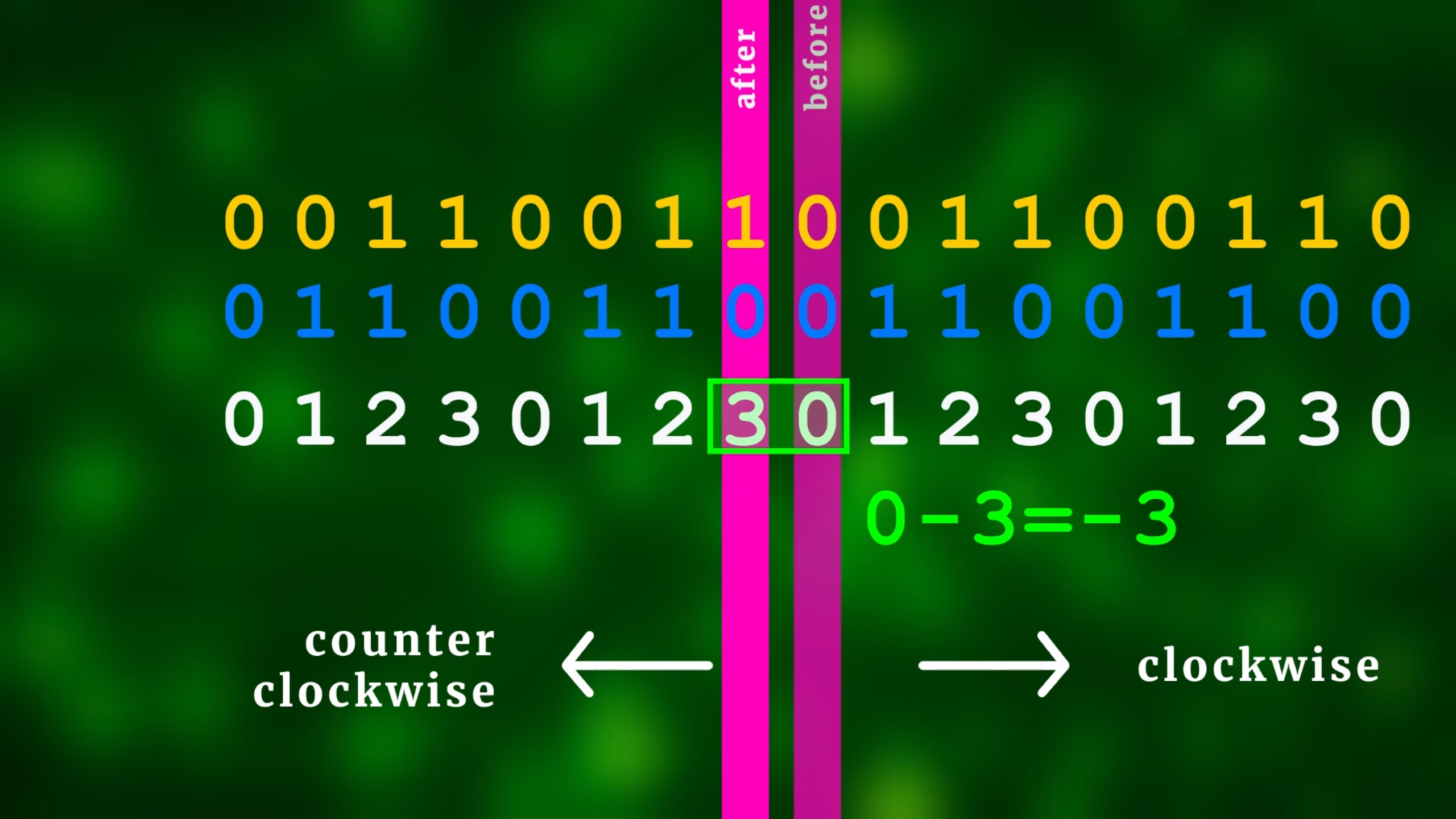
So: by calculatin the difference, we know exactly in which direction the rotary encoder was turned!
Now, we need to make sure we check frequently enough, and in regular time intervals. So it's not a good idea to to it inside a main loop. It's much better to do the checking iside an interrupt service routine (ISR) that is called a few thousand times per second, and we will talk a bit more about that later.
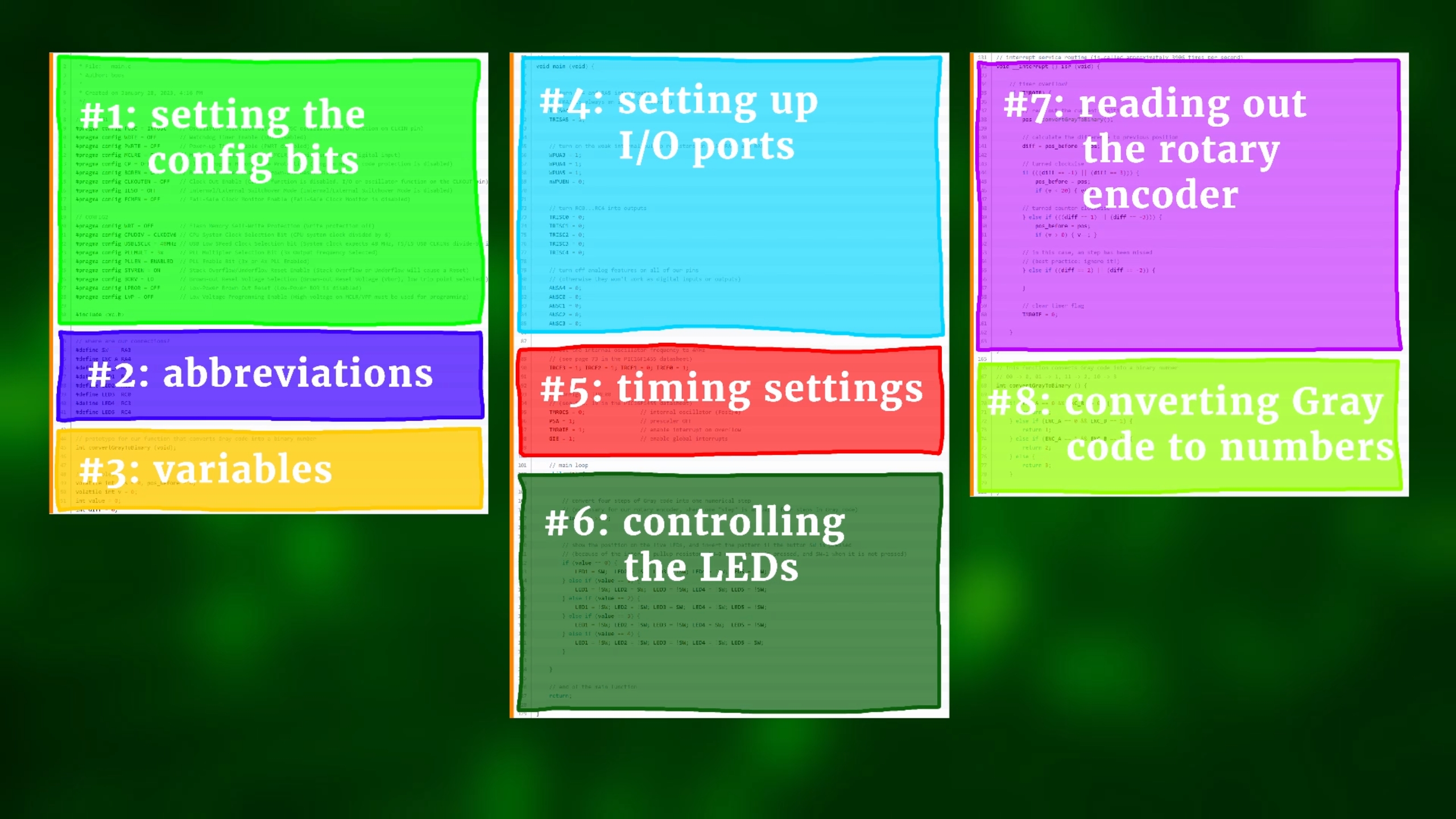
And here you can see the full program, with the colored parts highlighting the different sections of it. So, let's go through all of this, line by line, and understand what is happening!
First, as always, we need to set the configuration bits of our PIC16F1455 microcontroller. They are different for each microcontroller, and in our case this is what we do:
// CONFIG1
#pragma config FOSC = INTOSC    // Oscillator Selection Bits (INTOSC oscillator: I/O function on CLKIN pin)
#pragma config WDTE = OFF       // Watchdog Timer Enable (WDT disabled)
#pragma config PWRTE = OFF      // Power-up Timer Enable (PWRT disabled)
#pragma config MCLRE = OFF      // MCLR Pin Function Select (MCLR/VPP pin function is digital input)
#pragma config CP = OFF         // Flash Program Memory Code Protection (Program memory code protection is disabled)
#pragma config BOREN = OFF      // Brown-out Reset Enable (Brown-out Reset disabled)
#pragma config CLKOUTEN = OFF   // Clock Out Enable (CLKOUT function is disabled. I/O or oscillator function on the CLKOUT pin)
#pragma config IESO = OFF       // Internal/External Switchover Mode (Internal/External Switchover Mode is disabled)
#pragma config FCMEN = OFF      // Fail-Safe Clock Monitor Enable (Fail-Safe Clock Monitor is disabled)

// CONFIG2
#pragma config WRT = OFF        // Flash Memory Self-Write Protection (Write protection off)
#pragma config CPUDIV = CLKDIV6 // CPU System Clock Selection Bit (CPU system clock divided by 6)
#pragma config USBLSCLK = 48MHz // USB Low SPeed Clock Selection bit (System clock expects 48 MHz, FS/LS USB CLKENs divide-by is set to 8.)
#pragma config PLLMULT = 3x     // PLL Multipler Selection Bit (3x Output Frequency Selected)
#pragma config PLLEN = ENABLED  // PLL Enable Bit (3x or 4x PLL Enabled)
#pragma config STVREN = ON      // Stack Overflow/Underflow Reset Enable (Stack Overflow or Underflow will cause a Reset)
#pragma config BORV = LO        // Brown-out Reset Voltage Selection (Brown-out Reset Voltage (Vbor), low trip point selected.)
#pragma config LPBOR = OFF      // Low-Power Brown Out Reset (Low-Power BOR is disabled)
#pragma config LVP = OFF        // Low-Voltage Programming Enable (High-voltage on MCLR/VPP must be used for programming)

#include <xc.h>
In line 9 we set the oscillator mode to internal (so we don't need an external crystal), and in line 12 we disable the Master Clear pin (so we can use it as an input). In line 28 we turn off low-voltage programming mode. The rest is not so important, and we basically just turn off all additional features that we don't need in this project. And last, in line 30, we include the XC8 compiler header.
Now it's time to think about where to connect our rotary encoder inputs (A, B, and the pushbutton) and our five LEDs. For this reason I always like to use the #define command:
// where are our connections?
#define SW    RA3
#define ENC_A RA4
#define ENC_B RA5
#define LED1  RC2
#define LED2  RC1
#define LED3  RC0
#define LED4  RC3
#define LED5  RC4
This way, for example, LED3 is located at RC0. To turn it on, we could write RC0 = 1; but nobody would know what it means. Instead, thanks to the #define command, we can now write LED3 = 1; which I think is a lot more readable.
Next, we define a function and our variables:
// prototype for our function that converts Gray code into a binary number
int convertGrayToBinary (void);


// variables
volatile int pos = 0, pos_before = 0;
volatile int v = 0;
int value = 0;
int diff = 0;
So, in line 45 we define a function called convertGrayToBinary, and what it does (we will see below) is to take the Gray code value and convert it into a number. Next, in lines 49–52, we define our variables. The volatile keyword is necessary for variables that are accessed inside the interrupt service routine (ISR). This way the compiler knows that their values may change unexpectedly during program execution, and it treats them differently when generating a .hex-file. If you are confused by that: no worries! Just remember to use volatile for variables that appear inside the ISR. And we will also talk more about the ISR later.
This was all our preparations, and now we are ready for the main function, that is encapsulated by lines 55–56 as well as 125–129:
// main function
void main (void) {
	// end of the main function
    return;

}
Now, inside the main function, I like to first set up the tristate registers of our pins. This way we can tell the PIC16F1455 that, for example, pin RA4 will be an input, and pin RC0 will be an output, and so on. This is how it looks like:
	// turn RA4 and RA5 into inputs
	// (RA3 is always an input by default)
    TRISA4 = 1;
    TRISA5 = 1;


	// turn on the weak internal pullup resistors on RA3, RA4, and RA5
	WPUA3 = 1;
    WPUA4 = 1;
    WPUA5 = 1;
    nWPUEN = 0;
In lines 66–69 we also turn on the weak internal pull-up resistors. This is necessary because we will connect the rotary encoder's pins to the PIC16F1455's pins RA3, RA4, and RA5. The register nWPUEN looks a bit odd, but the “n” stands for “negated” which means that if we set nWPUEN = 0; then the pull-ups are enabled, and if we were to set nWPUEN = 1; then they would be, somewhat counter-intuitively, disabled.
And now we set RC0..RC4 all to outputs, because that's where our LEDs will be:
	// turn RC0...RC4 into outputs
    TRISC0 = 0;
    TRISC1 = 0;
    TRISC2 = 0;
    TRISC3 = 0;
    TRISC4 = 0;

	// turn off analog features on all of our pins
	// (otherwise they won't work as digital inputs or outputs)
    ANSA4 = 0;
    ANSC0 = 0;
    ANSC1 = 0;
    ANSC2 = 0;
    ANSC3 = 0;
The lines 81–85 are very important, because they turn off all analog features on our pins. This can be a bit tricky for beginners (and I know that I always forgot about this when I got started), and the only way to figure this one out, unfortunately, is to look into the datasheet and check which pins have analog functionality. Usually, this functionality is turned ON by default, so here we makle sure it is turned OFF. Only this way we can use our pins as simple digital inputs/outputs.
Remember that in line 9 we set the oscillator to internal? Well, now is the time to set its frequency, and for today's tutorial we are going with a moderate 4MHz (check the datasheet on page 73 if you want a different speed):
	// set the internal oscillator frequency to 4MHz
	// (see page 73 in the PIC16F1455 datasheet)
    IRCF3 = 1; IRCF2 = 1; IRCF1 = 0; IRCF0 = 1;
Now, our program also uses an interrupt service routine (ISR). That is basically a function that gets called whenever an interrupt happens (a pre-defined event), and for our tutorial today we want an interrupt to occur whenever TIMER0 flows over. What it boils down to: we want an interrupt to be caused a few thousand times per second, and whenever that happens, the ISR is called. These lines here configure TIMER0 so that it flows over 3906 times per second:
	// configure TIMER0
	// (see Sec. 19 in the PIC16F1455 datasheet)
    TMR0CS = 0;                 // internal oscillator (Fosc/4)
    PSA = 1;                    // prescaler OFF
    TMR0IE = 1;                 // enable interrupt on overflow
    GIE = 1;                    // enable global interrupts
And then, in lines 87–98 we make sure that an interrupt is created every time TIMER0 flows over.
And, my goodness, we havfe made it to the main loop! This loop is a cyclic structure you can find in most microcontroller programs, and it is repeated over and over and over, forever. This is how our main loop looks like:
	// main loop
    while (1) {


        // convert four steps of Gray code into one numerical step
        // (necessary for our rotary encoder, where one "step" is actually four steps in Gray code)
        value = v >> 2;


        // show the position on the five LEDs, and invert the pattern if the button SW is pressed
        // (because of the internal pullup resistor, SW=0 whenever it is pressed, and SW=1 when it is not pressed)
        if (value == 0) {
            LED1 = SW;  LED2 = !SW; LED3 = !SW; LED4 = !SW; LED5 = !SW;
        } else if (value == 1) {
            LED1 = !SW; LED2 = SW;  LED3 = !SW; LED4 = !SW; LED5 = !SW;
        } else if (value == 2) {
            LED1 = !SW; LED2 = !SW; LED3 = SW;  LED4 = !SW; LED5 = !SW;
        } else if (value == 3) {
            LED1 = !SW; LED2 = !SW; LED3 = !SW; LED4 = SW;  LED5 = !SW;
        } else if (value == 4) {
            LED1 = !SW; LED2 = !SW; LED3 = !SW; LED4 = !SW; LED5 = SW;
        }

    }
There are two main parts: in line 107 we convert the rotary encoder variable v (which we talked about before, and which takes values from 0...19) and divide it by 4, so that the variable value is between 0...4. This tells us what LED to turn on.
And, speaking of which, this is exactly what lines 112–122 do. If value equals 0, we turn on LED1, and all others off. If value equals 1, we turn on LED2 and all other LEDs off, and so on.
But what about SW? What does that mean? SW is our built-in pushbutton. Remember that we are using internal pull-up resistors. So, SW reads as 1 whenever the pushbutton is NOT pressed. When it is pressed, however, SW reads as 0. And the ! operator simply inverts stuff, so: when SW is 1, then !SW is 0, and so on.
Whenever the pushbutton is pressed, we want to invert all LEDs, right? Let's assume that value is 0, for convenience. Then, all that line 113 amounts to, is the following. If the pusbutton is not pressed, it effectively becomes
LED1 = 1; LED2 = 0; LED3 = 0; LED4 = 0; LED5 = 0;If it is pressed, however, we instead have this:
LED1 = 0; LED2 = 1; LED3 = 1; LED4 = 1; LED5 = 1;So I hope you see that all of this just makes sure the LEDs get inverted. Phew. And that was the main loop! So now let's talk about the main part: how to read out the rotary enocer. And we do that inside the interrupt service routine:
// interrupt service routine (is called approximately 3906 times per second)
void __interrupt () isr (void) {

    // timer overflow?
    if (TMR0IF) {
}
// clear timer flag
TMR0IF = 0;
}
}So here is the beginning and end of the ISR. In the previous code we made sure this function gets called around 3906 times per second, and whenever it is called, the bit TMR0IF (TIMER0 interrupt flag) is set to 1. Inside the function, we just check if it is really 1 (because an interrupt could, in principle, also be caused by something else), and then, before leaving the ISR, we reset the interrupt flag back to 0 (line 159). In between is where the action happens:
// read out the current position
pos = convertGrayToBinary();
// calculate the difference to previous position
diff = pos_before - pos;In line 138 we convert the current rotary encoder signal (basically, the status of pin A and B) into a binary number between 0 and 3. We will talk more about this function below. Then, in line 141, we calculate the difference to the previously recorded position. Based on the properties of Gray code, as we saw above, this difference can either be -1 or 3 (in case of a clockwise rotation) or it can be 1 or -3 (in case of a counter-clockwise rotation). All other differences are wrong signals, which we will ignore. So, based on the value of diff, we now know in which direction the rotary encocer has been turned, so let us react to it:
// turned clockwise
if (((diff == -1) || (diff == 3))) {
pos_before = pos;
if (v < 20) { v++; }
// turned counter-clockwise
} else if (((diff == 1) || (diff == -3))) {
pos_before = pos;
if (v > 0) { v--; }
// in this case, an step has been missed
// (best practice: ignore it!)
} else if ((diff == 2) || (diff == -2)) {
}Remember that the variable v stores our rotary encoder position, and in our case we restrict it between 0 and 19, but in your application you may want it to be between -50 and 50, or 0 and 100, totally up to you :) The main step is just to increase this value for a clockwise rotation (line 146), and to decrease this variable for a counter-clockwise rotation (line 151).
Of course you could also increase for counter-clockwise, and decrease it for a clockwise rotation, it is also up to you. Basically, as soon as we know that the rotary encoder was turned, we can then manipulate our variables accordingly. That's really all that's to it :)
And we are finally almost done! The last puzzle piece is to convert the Gray code into binary. This conversion is kind of random, but I chose a typical one, wherein the numbers increase when you turn clockwise. Here is a simple way of how you can do it:
// this function converts Gray code into a binary number
// 00 -> 0, 01 -> 1, 11 -> 2, 10 -> 3
int convertGrayToBinary () {
if (ENC_A == 0 && ENC_B == 0) {
return 0;
} else if (ENC_A == 0 && ENC_B == 1) {
return 1;
} else if (ENC_A == 1 && ENC_B == 1) {
return 2;
} else {
return 3;
}
}The function just goes through all four possible cases the two rotary encoder pins ENC_A and ENC_B can be evaluated to, and assigns them an integer number. And that's it!
Now I know this code is a bit longer, and you may ask yourself: why do I need to write so much code to read out a silly rotary encoder? But I hope after looking at this explanation again (and also after watching the YouTube video) it looks less scary. You can do it, and I believe in you. If you have any questions for the source code, please let me know on social media, and I will do my best to get back to you :)
Flashing the controller
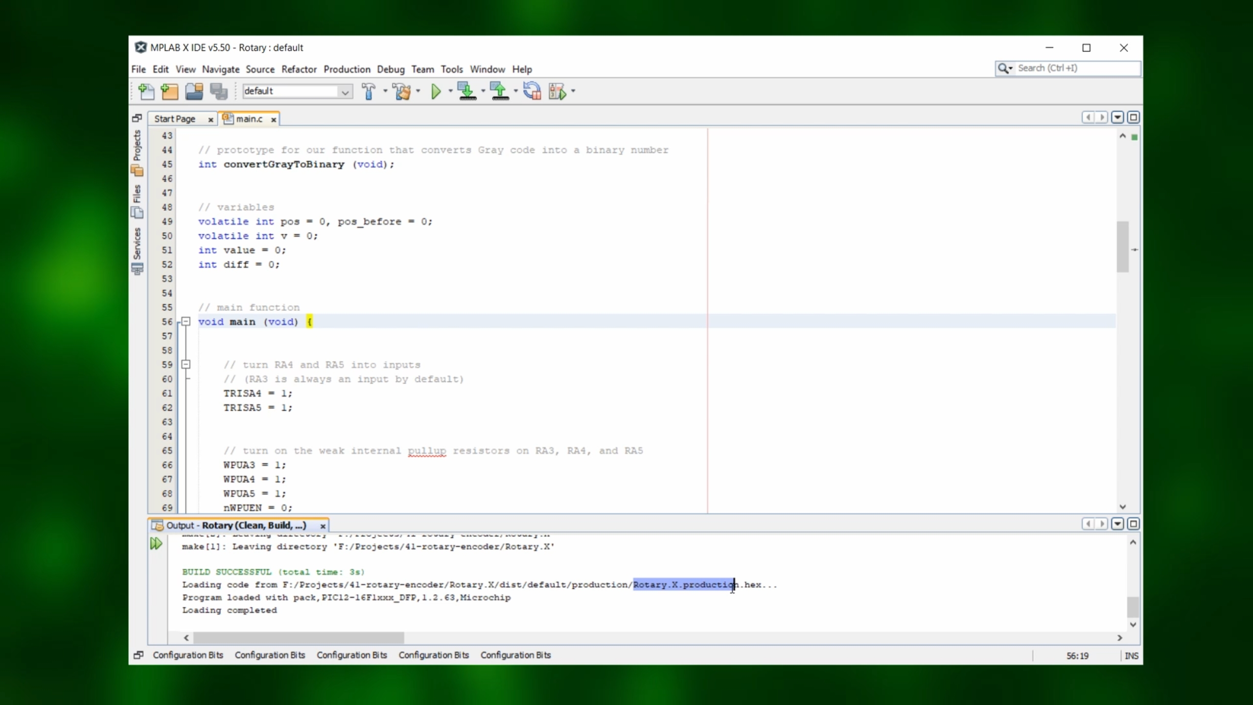
Now that we have the source code, create a project inside the MPLAB IDE and compile this code into a .hex-file. That's basically the code that the microcontroller can understand directly, and if you don't want to use the MPLAB IDE you can just download the rotary.hex file directly from the resources box, no coding needed.
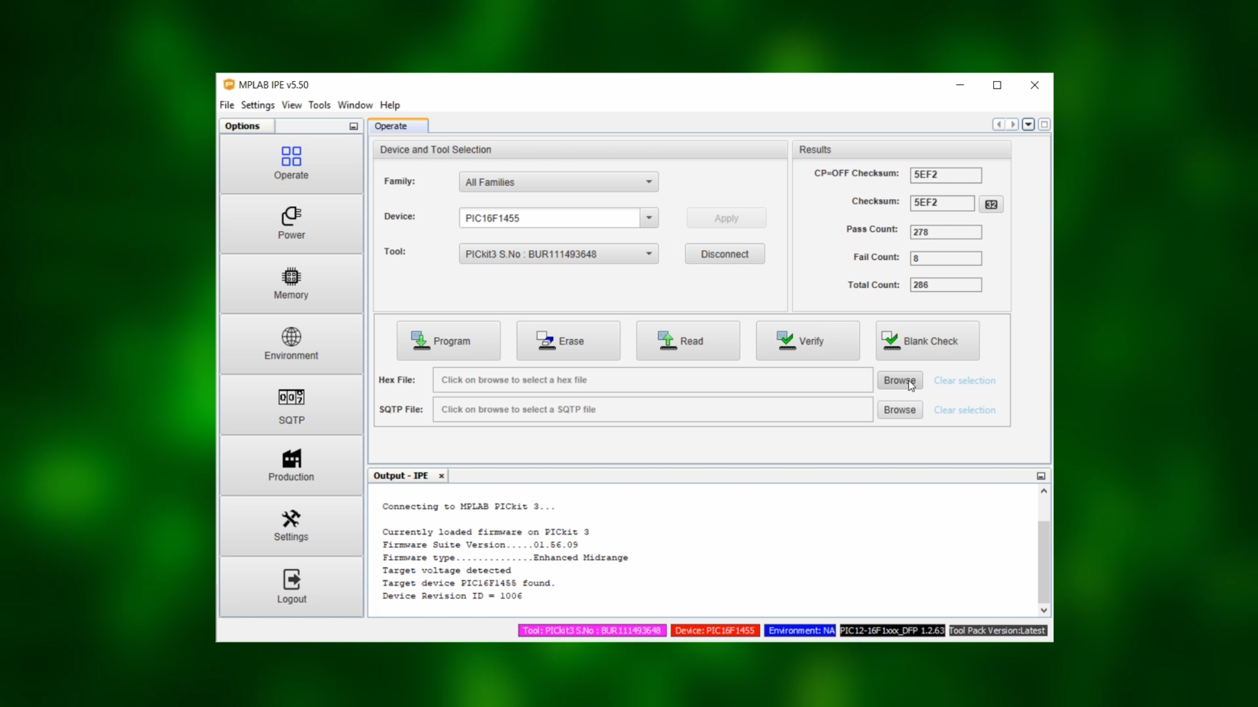
Now, start the MPLAB IPE, select the PIC16F1455 under "Device" and click on "Apply," and select the PICkit3 as your tool.
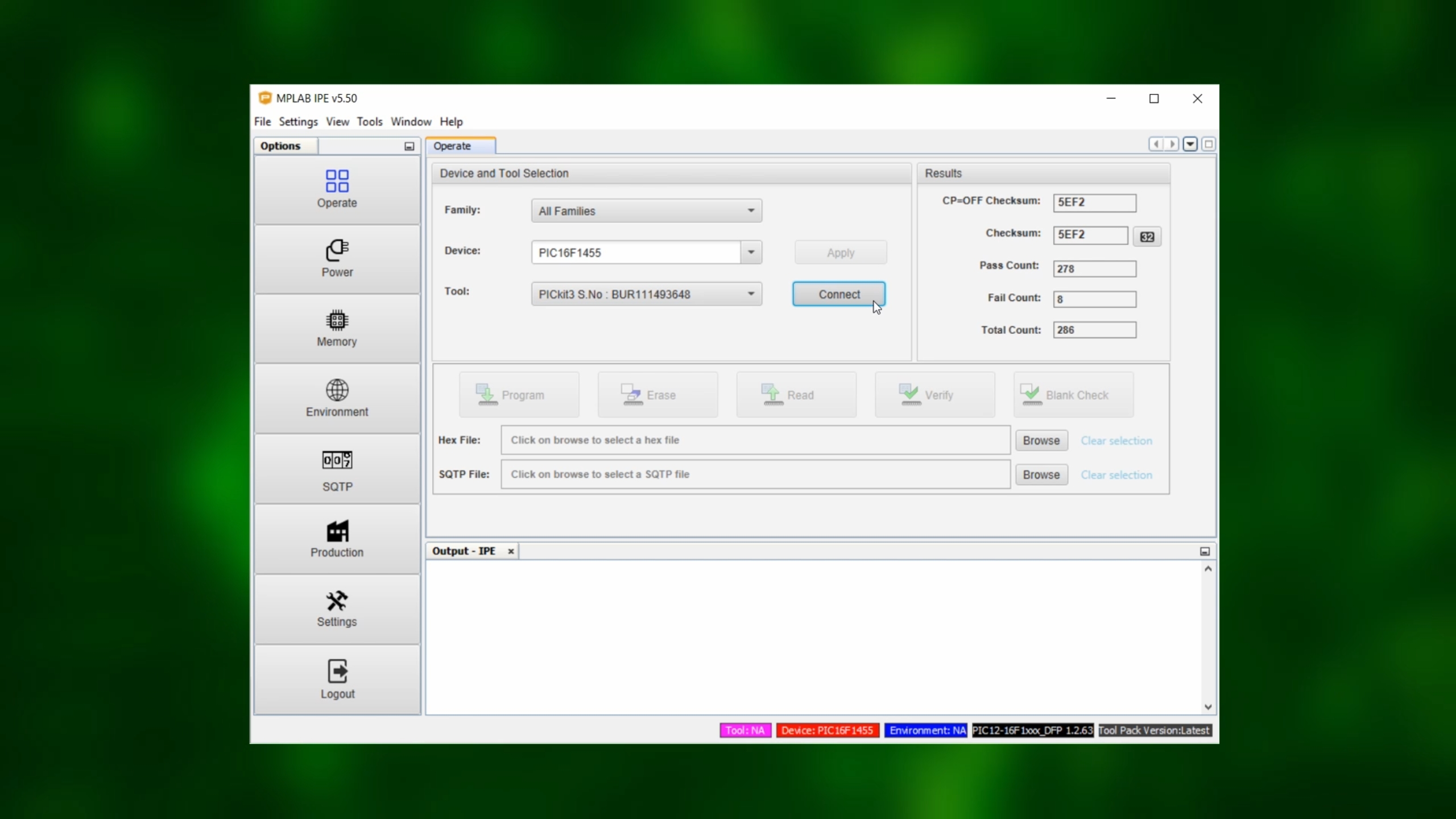
Click on "Connect," and wait for a bit.
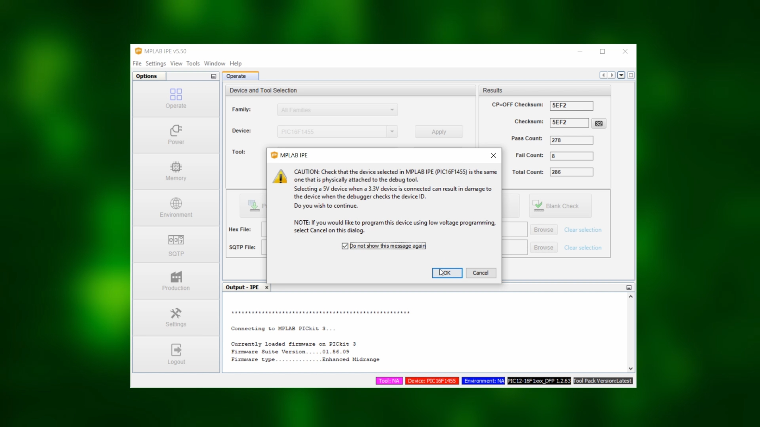
After this message appears (making sure that we are really using the PIC16F1455) you can confirm and click the checkbox, and cick on “OK.” After a few seconds, the PIC16F1455 should be detected:
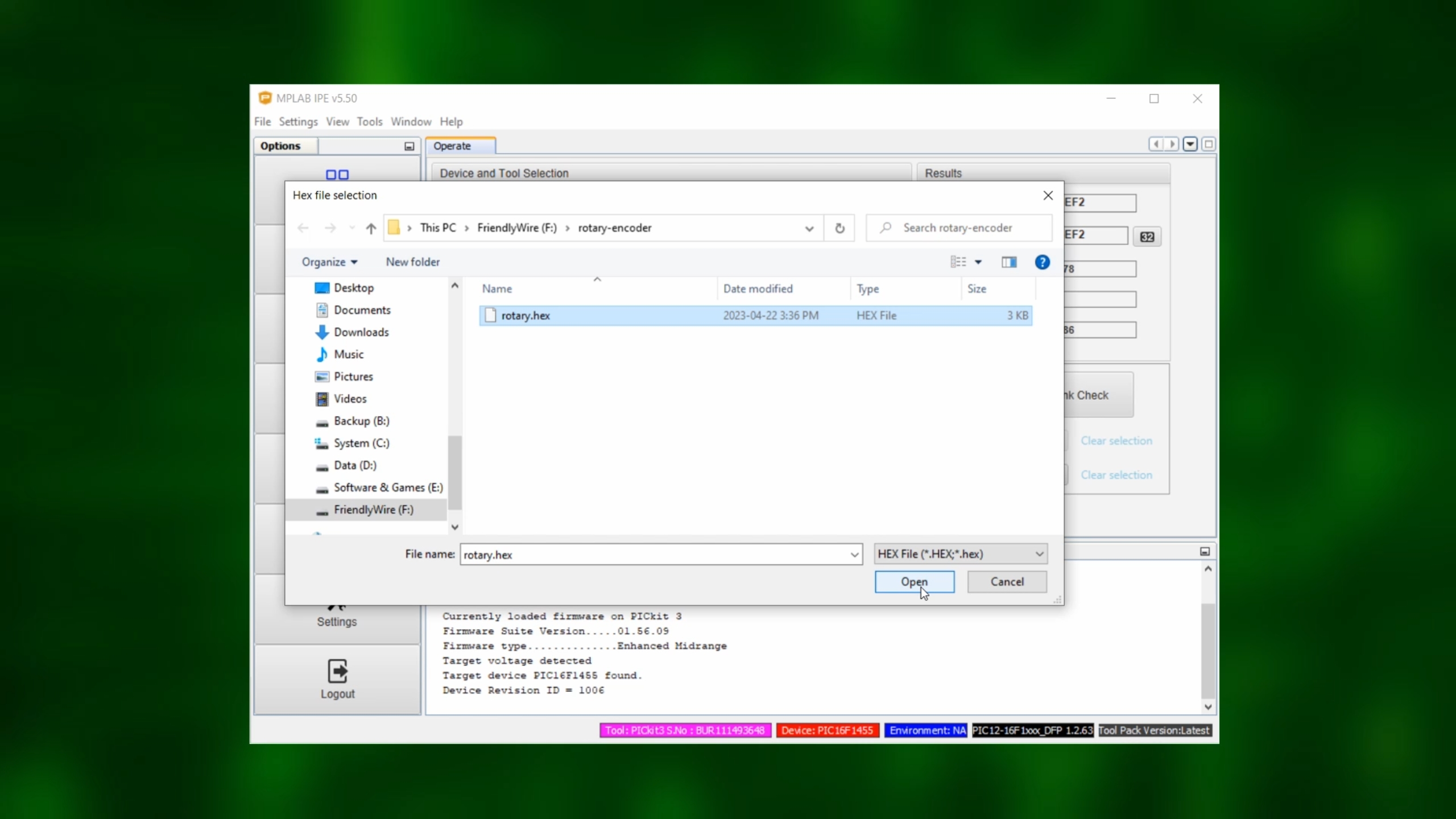
Now click on "Browse" and select the .hex-file:
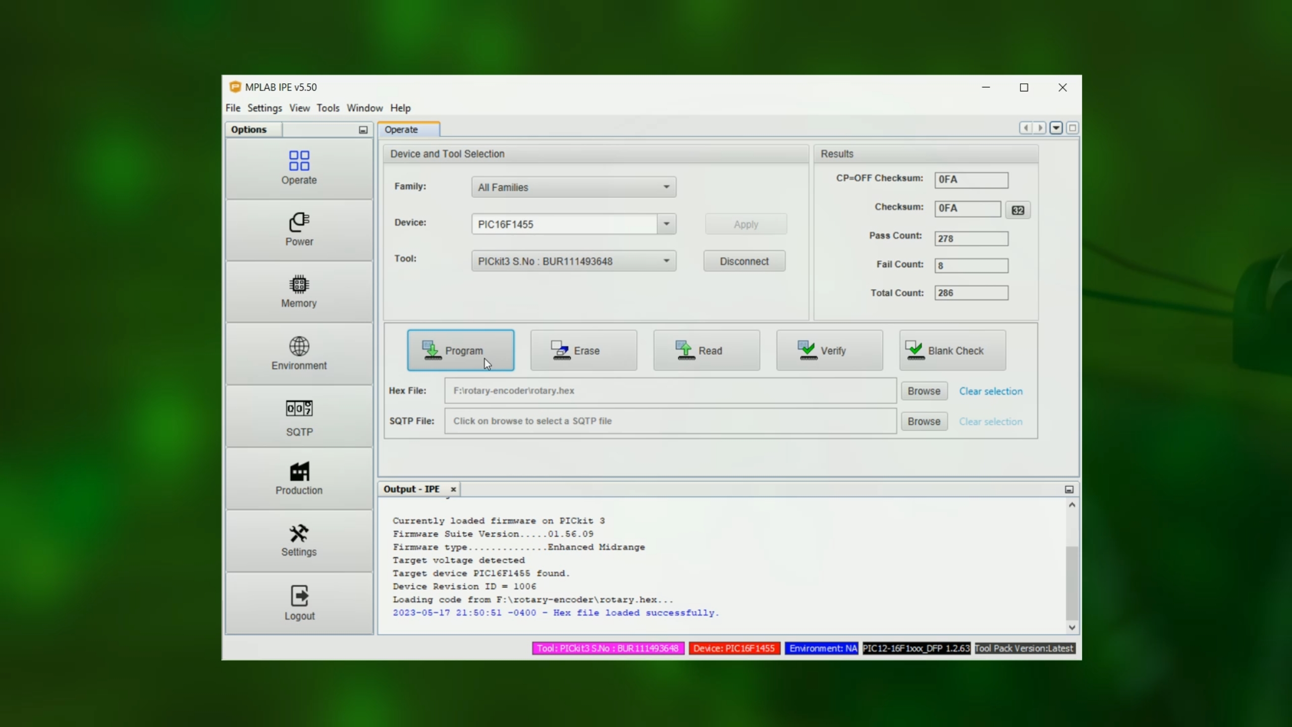
After it has been loaded, click on "Program." The PICkit3 LEDs should now start blinking, and after a few seconds we are done. The .hex-file has been successfully transferred onto the PIC16F1455!
We can now disconnect the PICkit3 from the breadboard, and play around with our rotary encoder.
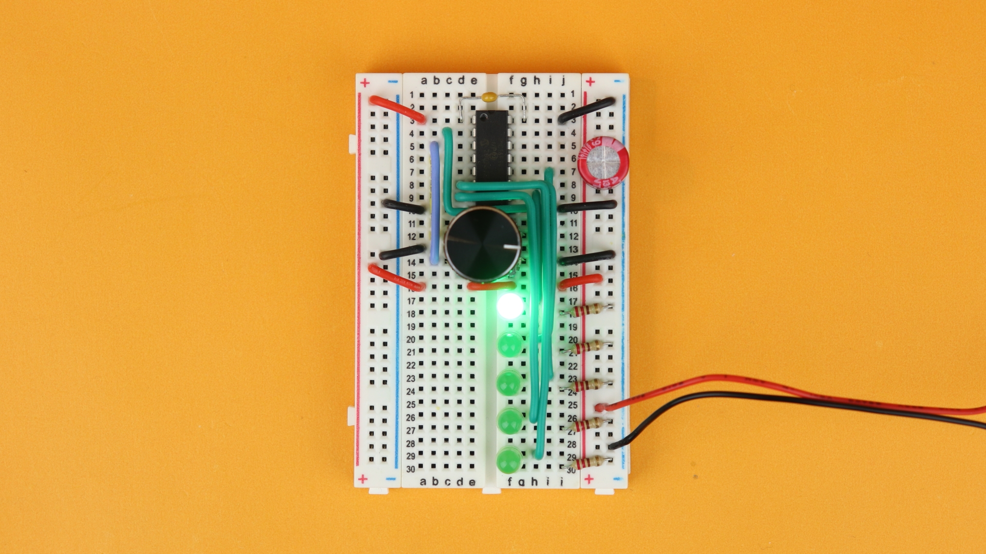
And we can even disconnect the onboard rotary encoder and connect the circuit to our homemade rotary encoder, and it still works:

YouTube video
I covered this entire tutorial in a dedicated YouTube video:
Final thoughts
Rotary encoders are one of those really satisfying input devices that I always wanted to understand better. It's just so much more pleasant to adjust a time with a rotating knob than with a pushbutton, at least in my opinion. So I hope that in this tutorial I could inspire you to add one to your next project, too!
Sometimes, the algorithm that I use to decode the rotary encoder does not work 100% correctly: when both contacts bounce at the same time, strange jumps can happen. I found that with very cheap rotary encoders (and when turning very rapidly) this is more prone to happen (because their contacts are not as well made), but it would be interesting to see how the algorithm from this tutorial could be improved to deal with more noisy signals. For every day purposes, though, the solution presented here works well enough for me, and I hope you will find it useful, too.
Anyway, I hope you enjoyed this tutorial, thank you for reading, and I will see you next time!
Appendix: source code
Here you can find the full source code. The code (as well as the .hex file) are also available for download in the resources box.
/*
* File: main.c
* Author: boos
*
* Created on January 28, 2023, 4:16 PM
*/
// CONFIG1
#pragma config FOSC = INTOSC // Oscillator Selection Bits (INTOSC oscillator: I/O function on CLKIN pin)
#pragma config WDTE = OFF // Watchdog Timer Enable (WDT disabled)
#pragma config PWRTE = OFF // Power-up Timer Enable (PWRT disabled)
#pragma config MCLRE = OFF // MCLR Pin Function Select (MCLR/VPP pin function is digital input)
#pragma config CP = OFF // Flash Program Memory Code Protection (Program memory code protection is disabled)
#pragma config BOREN = OFF // Brown-out Reset Enable (Brown-out Reset disabled)
#pragma config CLKOUTEN = OFF // Clock Out Enable (CLKOUT function is disabled. I/O or oscillator function on the CLKOUT pin)
#pragma config IESO = OFF // Internal/External Switchover Mode (Internal/External Switchover Mode is disabled)
#pragma config FCMEN = OFF // Fail-Safe Clock Monitor Enable (Fail-Safe Clock Monitor is disabled)
// CONFIG2
#pragma config WRT = OFF // Flash Memory Self-Write Protection (Write protection off)
#pragma config CPUDIV = CLKDIV6 // CPU System Clock Selection Bit (CPU system clock divided by 6)
#pragma config USBLSCLK = 48MHz // USB Low SPeed Clock Selection bit (System clock expects 48 MHz, FS/LS USB CLKENs divide-by is set to 8.)
#pragma config PLLMULT = 3x // PLL Multipler Selection Bit (3x Output Frequency Selected)
#pragma config PLLEN = ENABLED // PLL Enable Bit (3x or 4x PLL Enabled)
#pragma config STVREN = ON // Stack Overflow/Underflow Reset Enable (Stack Overflow or Underflow will cause a Reset)
#pragma config BORV = LO // Brown-out Reset Voltage Selection (Brown-out Reset Voltage (Vbor), low trip point selected.)
#pragma config LPBOR = OFF // Low-Power Brown Out Reset (Low-Power BOR is disabled)
#pragma config LVP = OFF // Low-Voltage Programming Enable (High-voltage on MCLR/VPP must be used for programming)
#include <xc.h>
// where are our connections?
#define SW RA3
#define ENC_A RA4
#define ENC_B RA5
#define LED1 RC2
#define LED2 RC1
#define LED3 RC0
#define LED4 RC3
#define LED5 RC4
// prototype for our function that converts Gray code into a binary number
int convertGrayToBinary (void);
// variables
volatile int pos = 0, pos_before = 0;
volatile int v = 0;
int value = 0;
int diff = 0;
// main function
void main (void) {
// turn RA4 and RA5 into inputs
// (RA3 is always an input by default)
TRISA4 = 1;
TRISA5 = 1;
// turn on the weak internal pullup resistors on RA3, RA4, and RA5
WPUA3 = 1;
WPUA4 = 1;
WPUA5 = 1;
nWPUEN = 0;
// turn RC0...RC4 into outputs
TRISC0 = 0;
TRISC1 = 0;
TRISC2 = 0;
TRISC3 = 0;
TRISC4 = 0;
// turn off analog features on all of our pins
// (otherwise they won't work as digital inputs or outputs)
ANSA4 = 0;
ANSC0 = 0;
ANSC1 = 0;
ANSC2 = 0;
ANSC3 = 0;
// set the internal oscillator frequency to 4MHz
// (see page 73 in the PIC16F1455 datasheet)
IRCF3 = 1; IRCF2 = 1; IRCF1 = 0; IRCF0 = 1;
// configure TIMER0
// (see Sec. 19 in the PIC16F1455 datasheet)
TMR0CS = 0; // internal oscillator (Fosc/4)
PSA = 1; // prescaler OFF
TMR0IE = 1; // enable interrupt on overflow
GIE = 1; // enable global interrupts
// main loop
while (1) {
// convert four steps of Gray code into one numerical step
// (necessary for our rotary encoder, where one "step" is actually four steps in Gray code)
value = v >> 2;
// show the position on the five LEDs, and invert the pattern if the button SW is pressed
// (because of the internal pullup resistor, SW=0 whenever it is pressed, and SW=1 when it is not pressed)
if (value == 0) {
LED1 = SW; LED2 = !SW; LED3 = !SW; LED4 = !SW; LED5 = !SW;
} else if (value == 1) {
LED1 = !SW; LED2 = SW; LED3 = !SW; LED4 = !SW; LED5 = !SW;
} else if (value == 2) {
LED1 = !SW; LED2 = !SW; LED3 = SW; LED4 = !SW; LED5 = !SW;
} else if (value == 3) {
LED1 = !SW; LED2 = !SW; LED3 = !SW; LED4 = SW; LED5 = !SW;
} else if (value == 4) {
LED1 = !SW; LED2 = !SW; LED3 = !SW; LED4 = !SW; LED5 = SW;
}
}
// end of the main function
return;
}
// interrupt service routine (is called approximately 3906 times per second)
void __interrupt () isr (void) {
// timer overflow?
if (TMR0IF) {
// read out the current position
pos = convertGrayToBinary();
// calculate the difference to previous position
diff = pos_before - pos;
// turned clockwise
if (((diff == -1) || (diff == 3))) {
pos_before = pos;
if (v < 20) { v++; }
// turned counter-clockwise
} else if (((diff == 1) || (diff == -3))) {
pos_before = pos;
if (v > 0) { v--; }
// in this case, an step has been missed
// (best practice: ignore it!)
} else if ((diff == 2) || (diff == -2)) {
	}
		// clear timer flag
        TMR0IF = 0;

    }

}
// this function converts Gray code into a binary number
// 00 -> 0, 01 -> 1, 11 -> 2, 10 -> 3
int convertGrayToBinary () {

    if (ENC_A == 0 && ENC_B == 0) {
        return 0;
    } else if (ENC_A == 0 && ENC_B == 1) {
        return 1;
    } else if (ENC_A == 1 && ENC_B == 1) {
        return 2;
    } else {
        return 3;
    }

}


