How do old school analog panel meters work?
October 27, 2019 • tutorial
Panel meters are simple electromechanic devices that can be used to measure currents, voltages, and resistances. Even though they seem to fade away in today's ever more digital electronics world, I think it is worthwhile to learn a little bit about them. How do they work? And how can we use them in electronics to measure stuff?
Basics of measuring current, voltage, and resistance
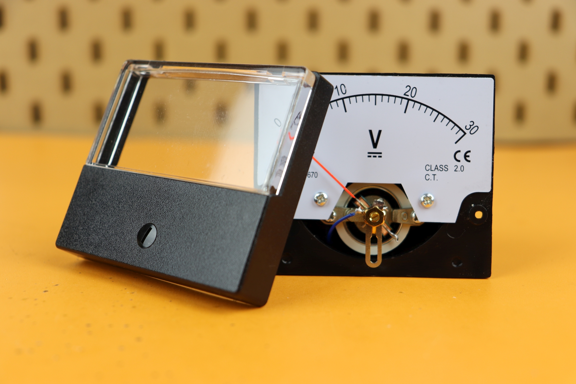
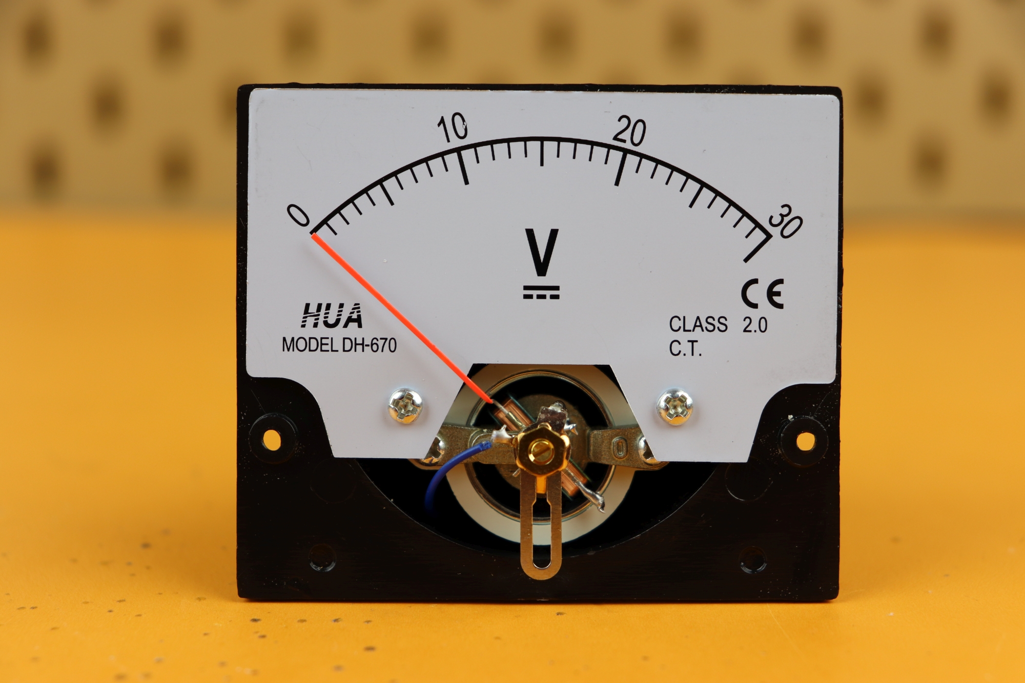
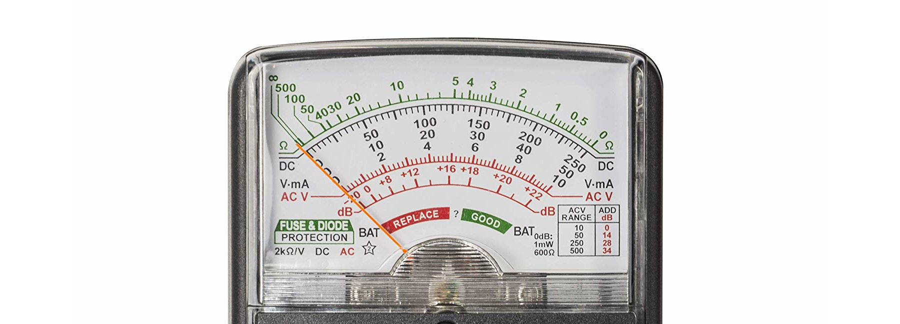
Here you can see a typical panel meter, this one measures a DC voltage between 0 and 30V:
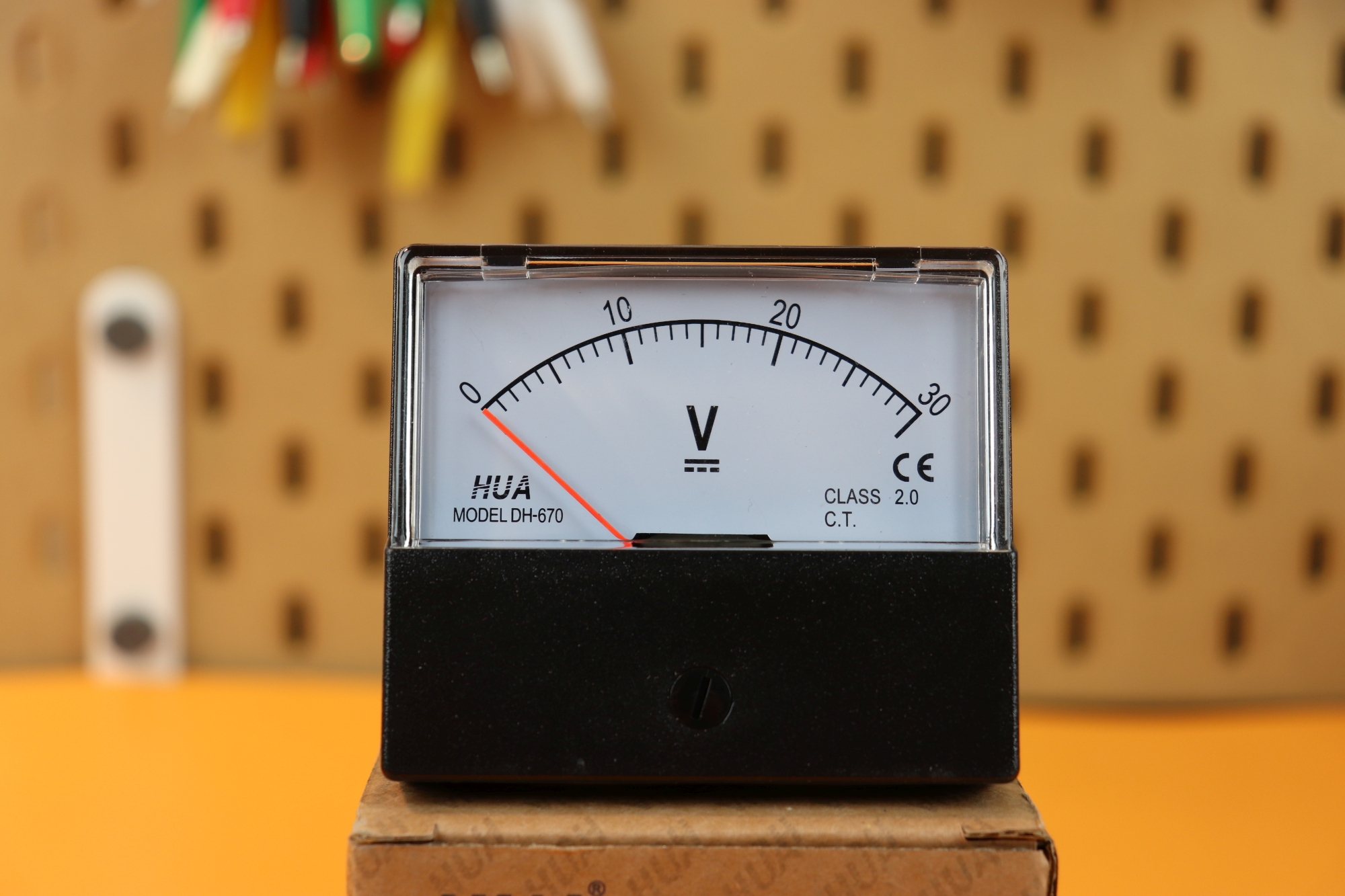
There are two connections on the back, labeled “+” and “-” where you connect the positive and negative terminal, respectively. The flathead screw below the scale can be used to calibrate the display. Say you connect 30V DC to this meter, and the display only shows 29V (but you are sure that it is really 30V). Then you can turn the screw around to set the meter to 30V.
Before we go into the details of how panel meters work, let's talk briefly about how we can use them to measure the voltage and current. There is three devices: the power supply S, the meter M, and whatever device D we have connected to it. All of these have two terminals that we will call “+” and “-” (and in the AC case you can ignore that). Here is how you measure the voltage:
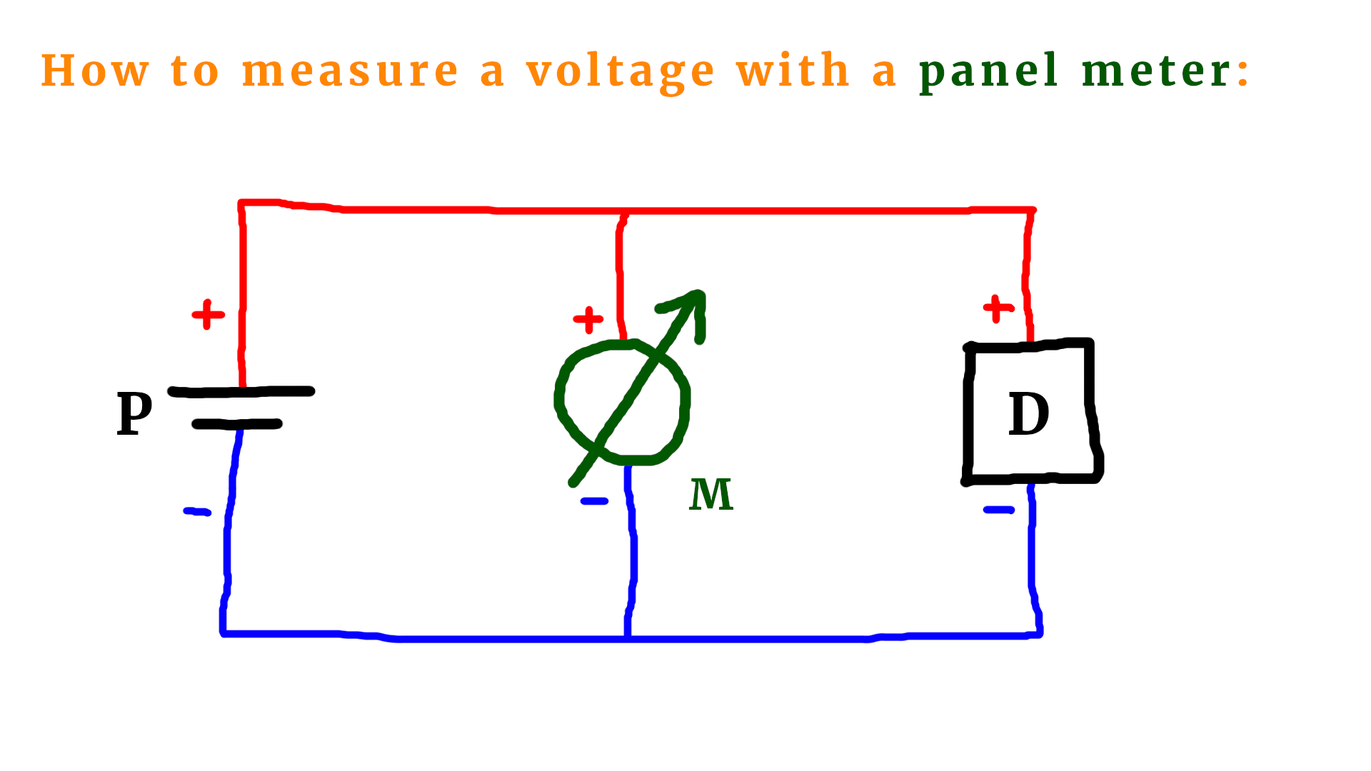
- Voltage is measured in parallel.
- Just connect the positive terminal of your meter to the positive terminal of your power supply (or device), and similarly for the negative terminal.
This is how you can measure the current:
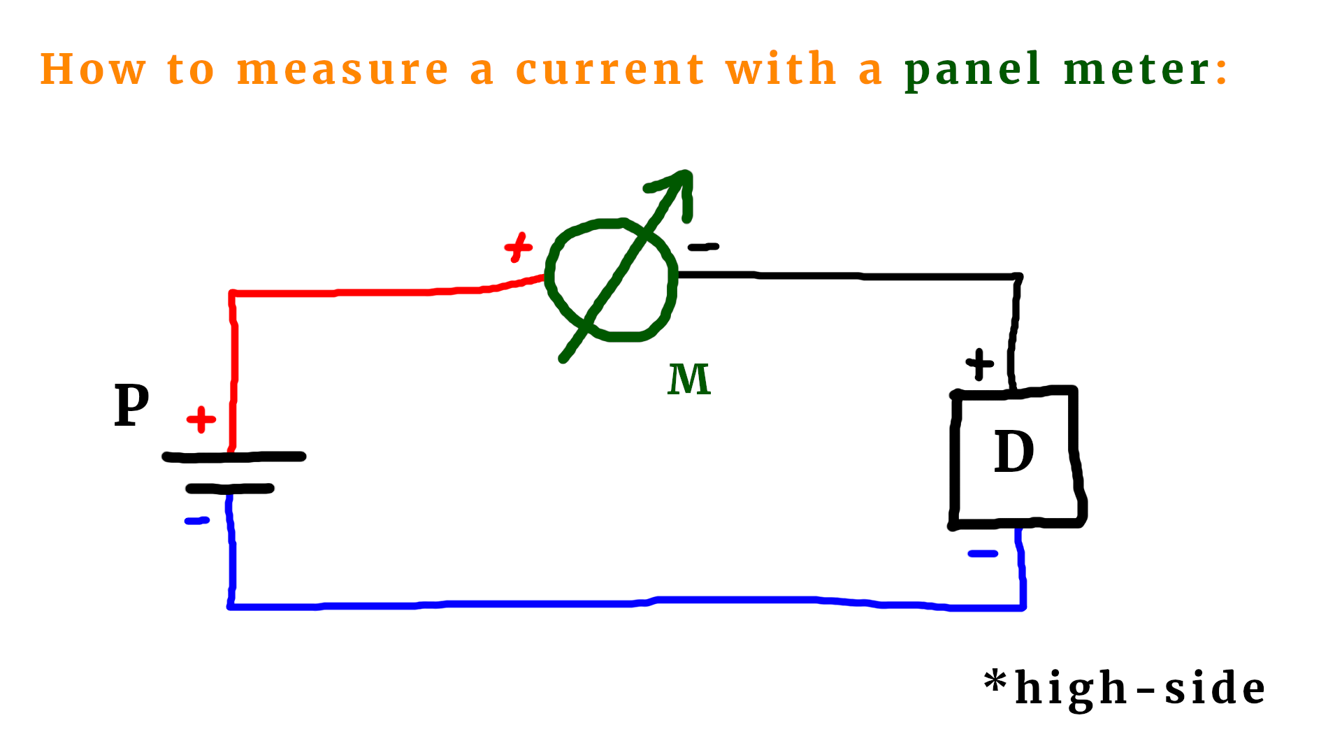
- Current is measured in series.
- Simply insert the meter in between the power source P and your device D.
- If you connect the positive terminal of the meter to the positive terminal of the power source S, then this is called a “high-side” measurement.
There is another way to measure the current:
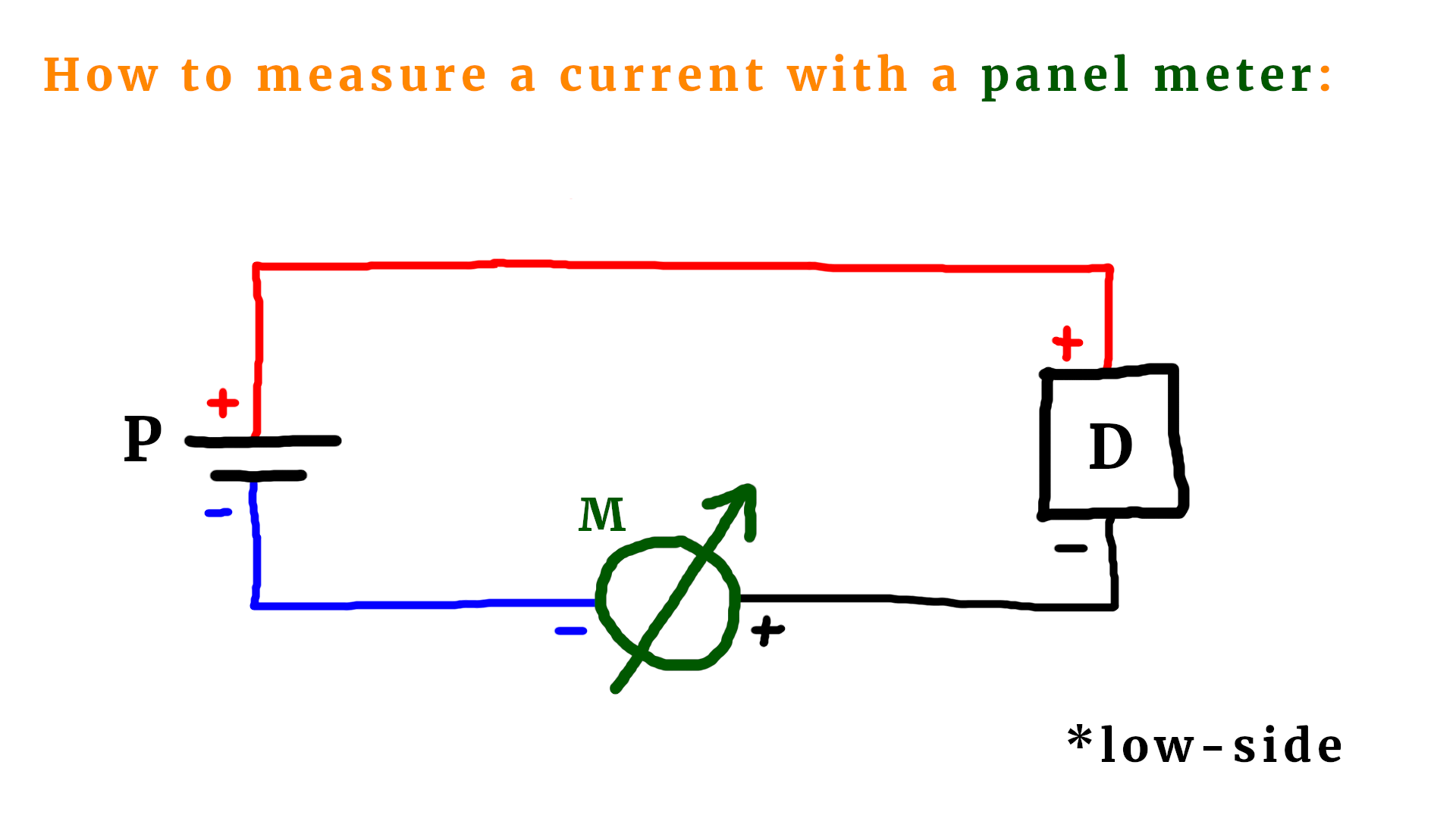
- If you connect the negative terminal of the meter to the negative terminal of the power source S, then this is called a “low-side” measurement.
And, finally, this is how you can measure the resistance:
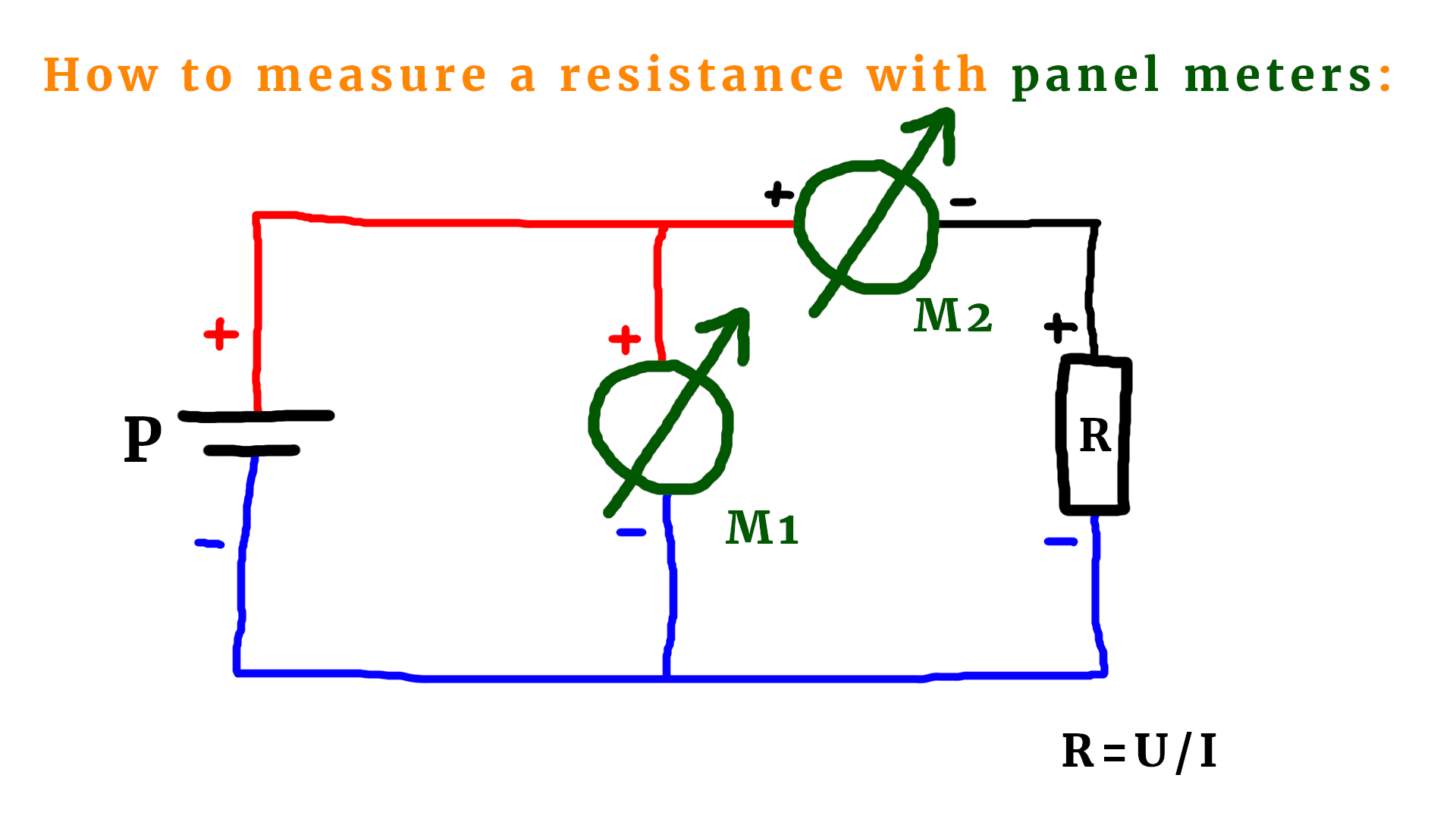
- This is a combination: you need to know the current that is flowing, and you need to know the voltage that drops across the resistor.
- Voltage and current are measured as described above.
- Then, you can use Ohm's law and calculate the value of the resistance.
Okay, now we know how to connect a panel meter to a circuit to measure the voltage, current, or resistance. But how does a panel meter really work?
How does a panel meter work?
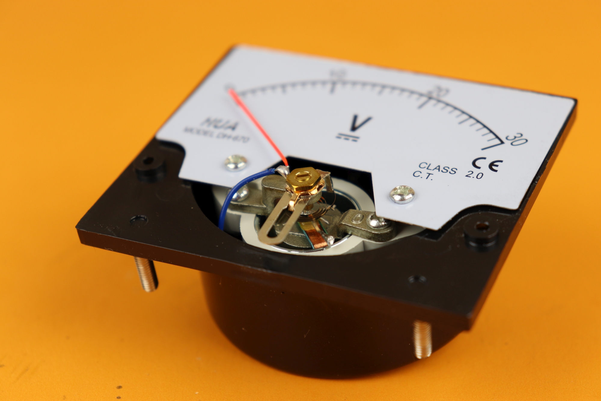
Most panel meters have a couple of screws that let you take off the front cover:
Then you can see that the indicator is connected to a coil:
Here you can see a close-up:
The coil works as a simple electromagnet. This means that if you apply a voltage to the coil and a current flows through it, it magnetizes its iron core and creates a magnetic field:
The laws of electromagnetism say that the magnetic field increases with the current: they are proportional! If you double the current, you double the magnetic field. Let's remember that :) Also we need to know that opposite poles attract (north attracts south, and south attracts north) and the same poles repulse each other. The voltage that we apply, and the current that flows through the wires is the quantity that we want to measure.
Here is an animation of how a panel meter works:
-
-
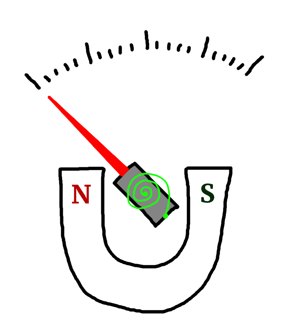
Step 1
There is no current, and the electromagnet is off. The horseshoe magnet has no effect. The green torsion spring is relaxed.
If the pointer does not point to zero at this moment, we could use the flathead screw we saw above to calibrate for that.
-

-
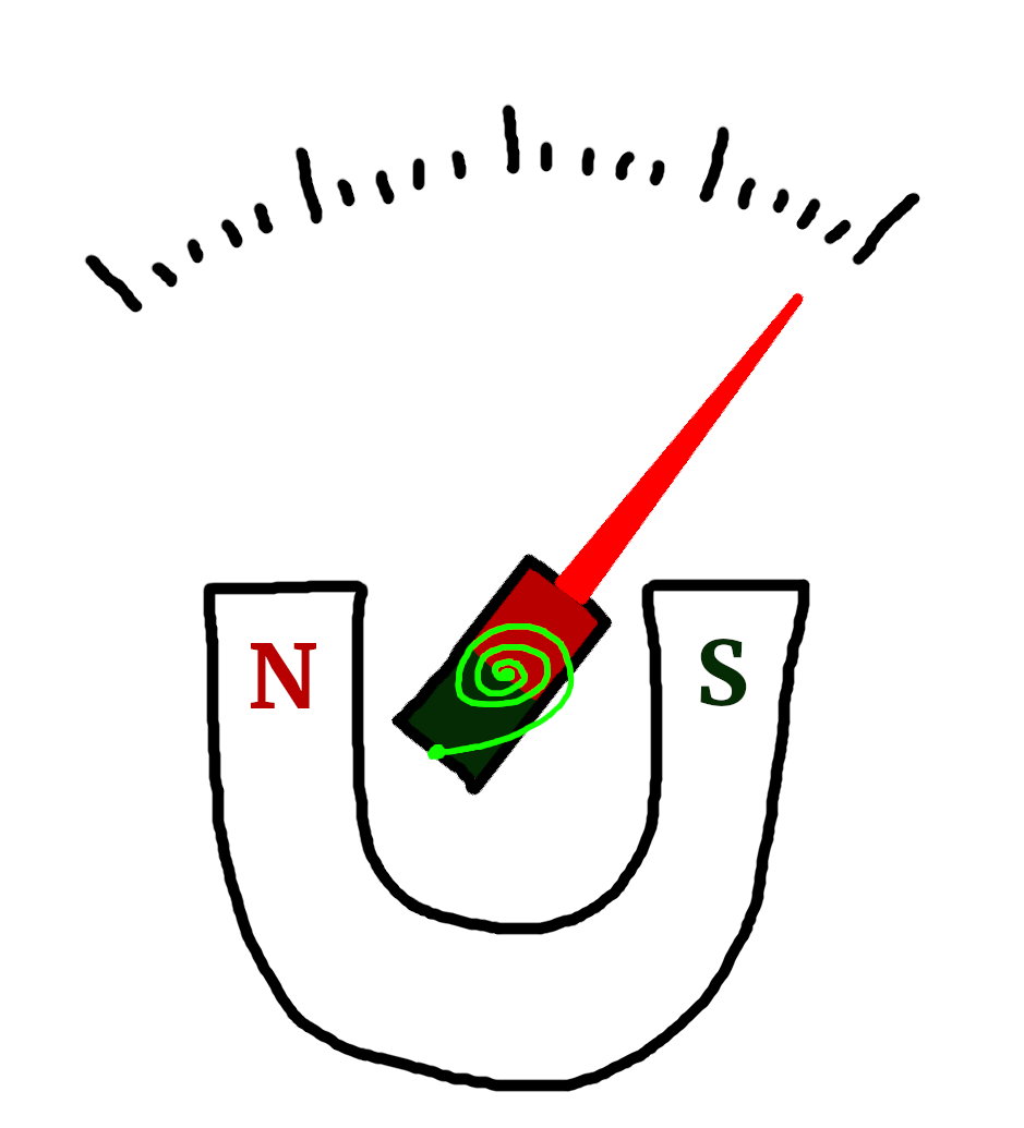
Step 2
There is some current flowing, and the electromagnet is weakly magnetized. This means that the north pole of the electromagnet repulses the north pole of the horseshoe magnet, and the indicator moves to the right.
The torsion spring is compressed a little bit. If the current stops flowing, this potential energy stored in the spring will move the dial back to zero.
-
-
Step 3
The maximum current is flowing, and the electromagnet is maximally magnetized. The scale is maxed out because the electromagnet's north pole maximally repulses the horseshoe magnet's north pole. The torsion spring is also extremely compressed.
Here you can see the whole process as an animation:
I hope the main idea has become clear. There are some technical details that we did not really discuss here:
- The electrical connection of the external wires to the electromagnet is a bit tricky because the electromagnet rotates during operation. Most commonly, the connection is done via the torsion spring which attaches to the middle of the magnet. Since that spring is made of metal it is already a conductor.
- There is a second torsion spring behind the electromagnet. I did not show it in the above diagrams because it would be hard to see.
- On the physics side, the torsion spring stores rotational potential energy that acts against the torque that is produced by the electromagnet in the magnetic field of the horseshoe magnet. It is very important that the angle of the indicator is proportional to the electric current flowing through the electromagnet.
If you want to learn more about it you can check out the excellent Wikipedia article on the ampere meter!
Important characteristics of a panel meter
Okay, now that we know how panel meters work, let us take a look at our example panel meter in more detail. Loosening two more screws reveals an interesting detail:
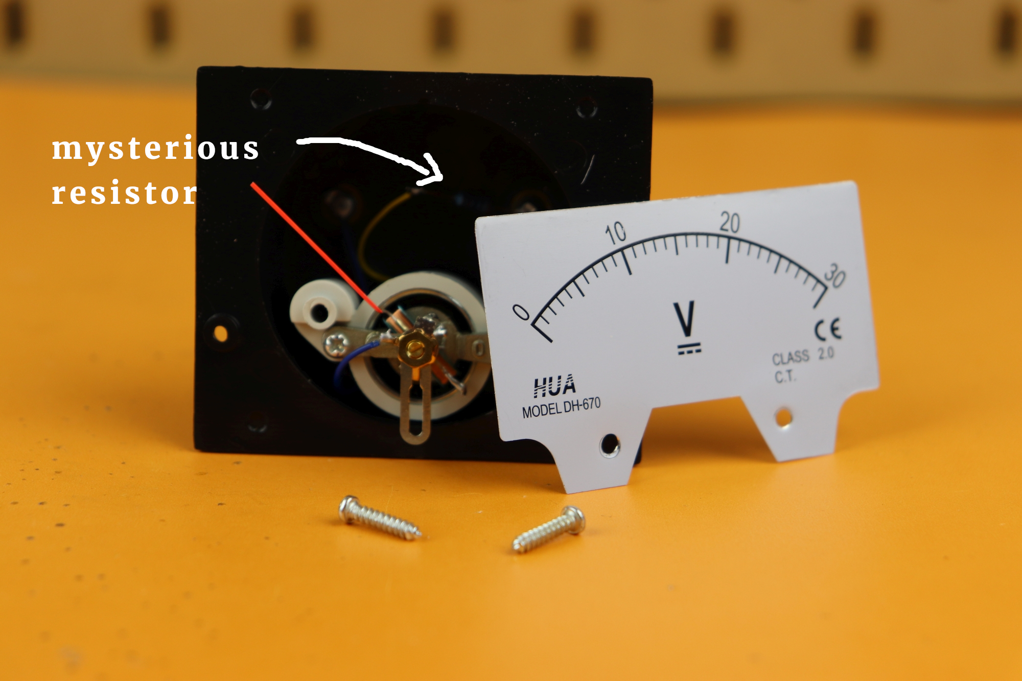
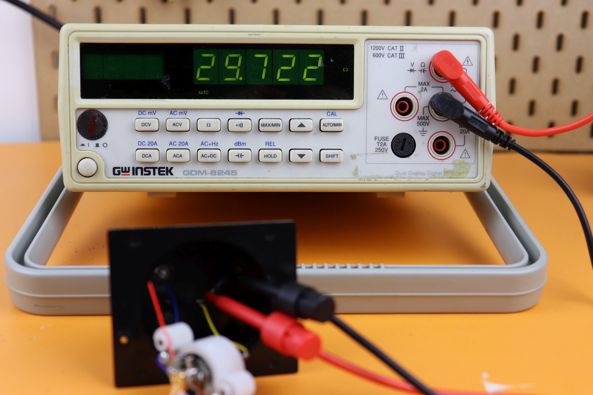
The scale comes off and reveals a mysterious resistor that is wired in series with the coil. Measuring it we find a value of about 30kΩ:
Let's try to understand this value. Clearly it has to be related to the fact that this panel meter is a voltmeter, and that it has a range of 30V. We need to know two important values to fully characterize a panel meter:
- The internal resistance Rint of the wire that makes up the electromagnet,
- and the saturation current Isat when the meter's display is maxed out.
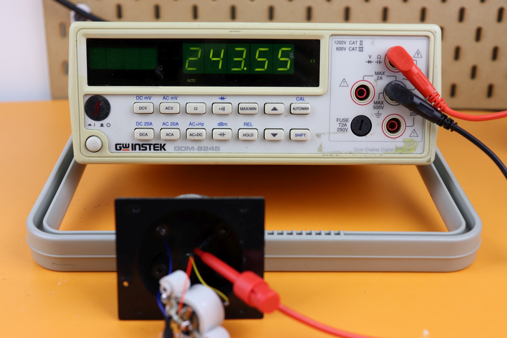
Luckily they are very easy to measure. The internal resistance can be measured by just connecting an ohmmeter directly to the coil, and we find a value of around 244Ω for Rint:
The saturation current can be found easily as well: just measure the current that flows when you connection 30V to the meter! For this panel meter we have an Isat of around 1mA:
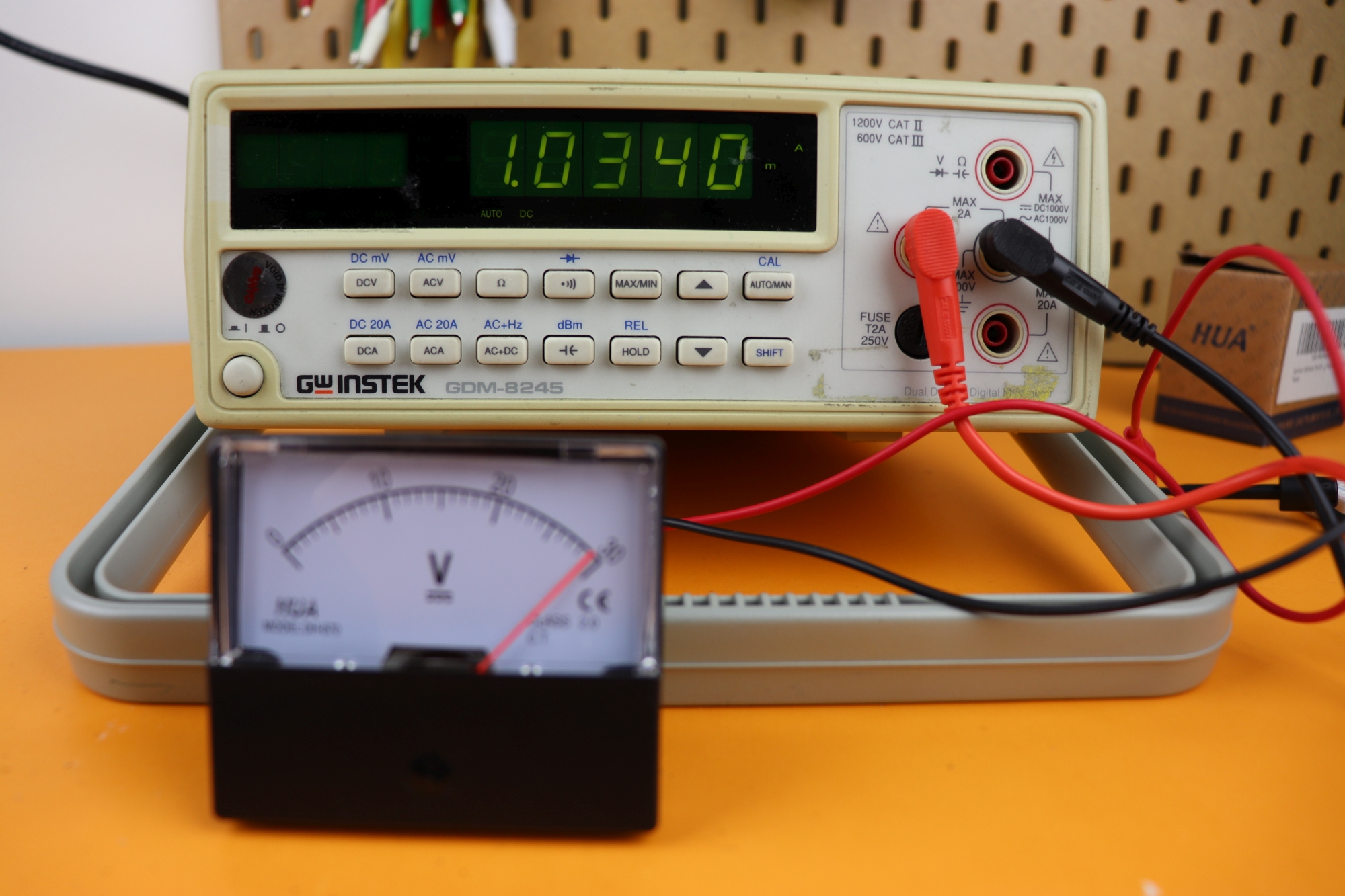
If your power supply does not provide 30V, you can just apply, say, 10V, and then multiply the current by 3. This is OK because the indicator position is linear in the current.
Now we have all we need. The voltmeter has this equivalent schematic:
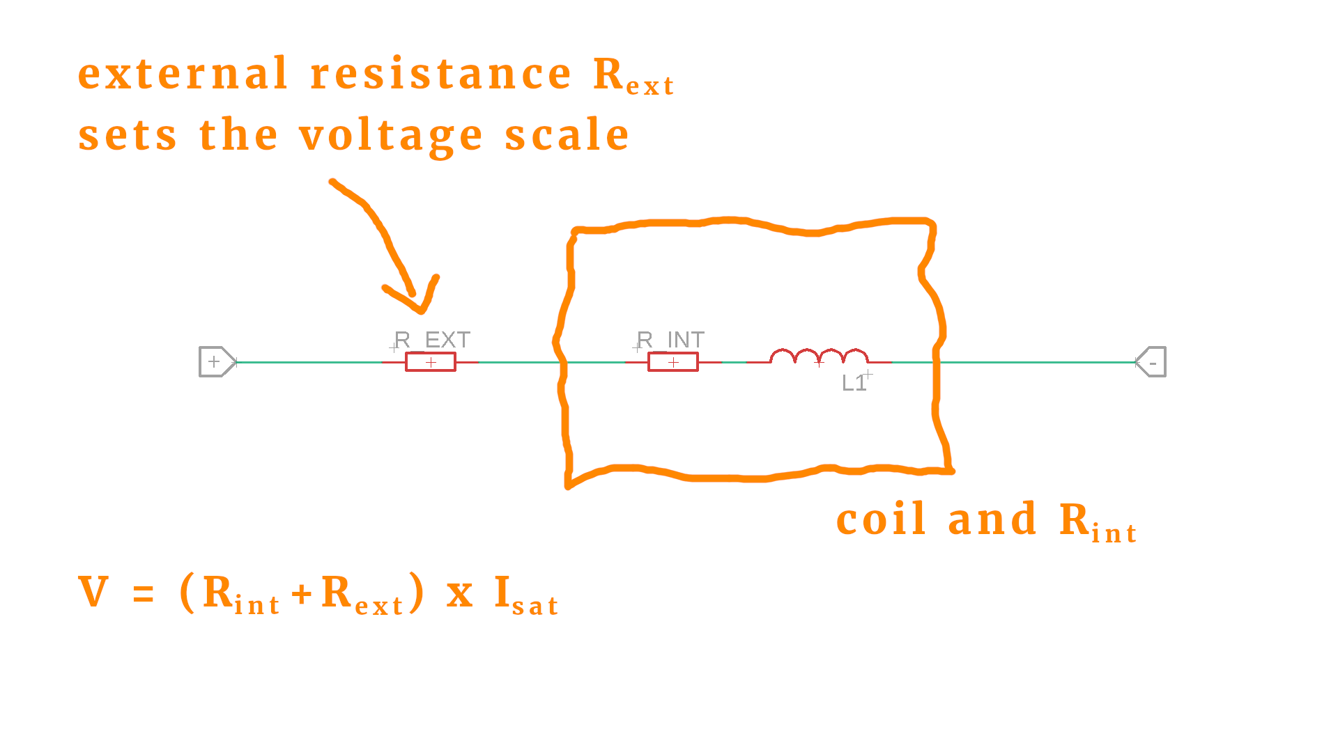
We used the coil symbol L1 to visualize the windings, and inserted the resistors Rint and Rext. Inserting our values Isat=1mA, Rint=244Ω and Rext=30kΩ into the formula we arrive at V=30V, which is spot on! The external resistor can be adjusted so that we can measure other voltages as well!
So, if you have a voltmeter that has the wrong scale, it is enough to know the saturation current and the internal resistance. Then you can use the above formula and solve for the external resistance.
Current measurement works very similarly. Now the external resistor has to be in parallel:
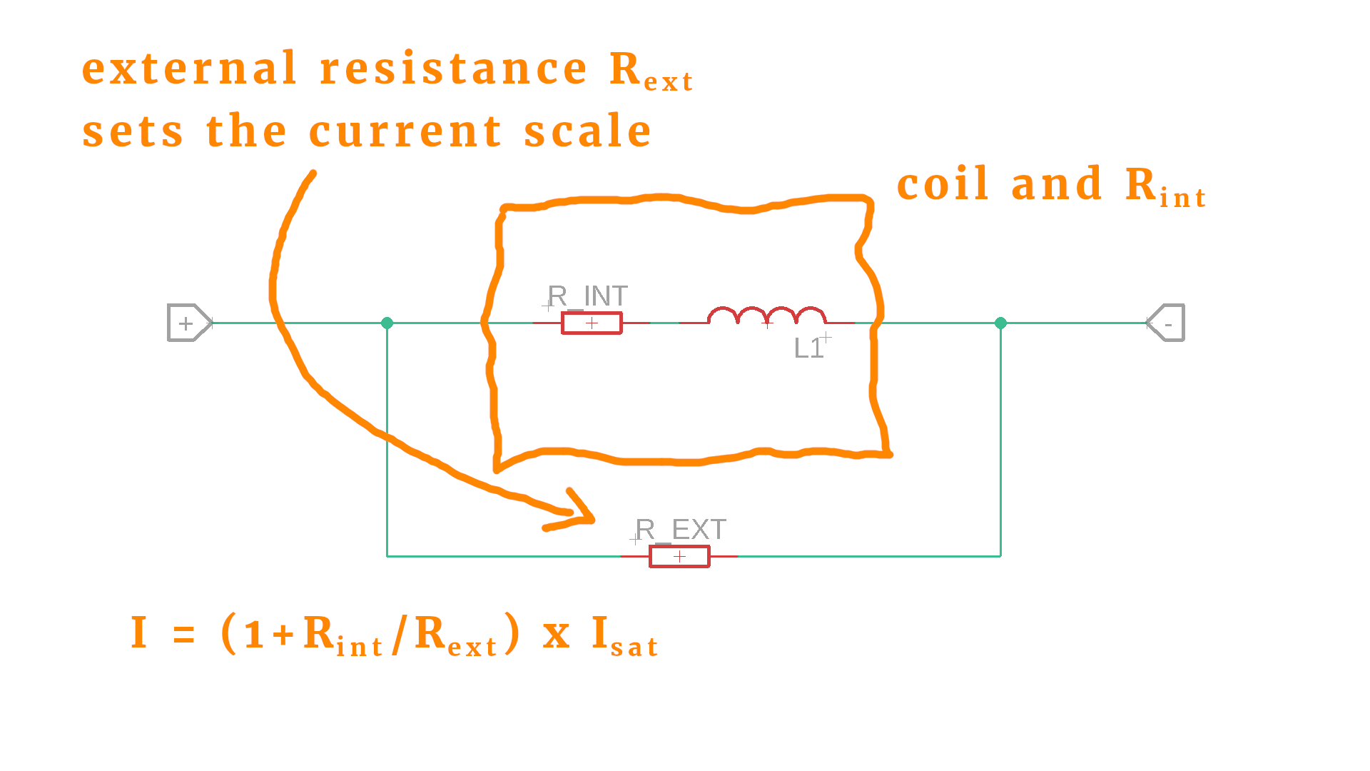
The logic is the same: by adjusting the parallel resistor you can alter the current that flows through the coil (because the current is shared between the coil and its parallel, external resistor).
And last, how do we measure resistances? This is easy, because we just measure the voltage drop across a resistor, and for that we can use the strategy described above for adjusting the voltage scale. There is one possible caveat: we need to know the current to do that, and for that we would need a constant current source. This can be easily done because we already talked about a constant current source in our LED article a long time ago :)
Final thoughts
I hope I could explain to you why analog panel meters are very interesting devices. They don't use any electronics, just pure physics. I think they are wonderfully clever devices, and I hope that the next time you see an analog meter you won't throw it onto the dust pile of history, but maybe take it apart and use it for your next project!


