Control LEDs with your computer using RS232
September 20, 2019 • tutorial • updated April 26, 2020
RS232? That sounds so 1990! Maybe so, but in this tutorial I want to show you why I still think RS232 is a great way to connect your PIC circuit to a computer or another PIC controller. Many PIC controllers have a built-in USART module that allows you to utilize the full power of the asynchronous data transmission and reception offered by protocols such as RS232. Let's do it!
Before we jump in, let's briefly address the elephant in the room: why not just use USB? It is true, USB might be a better choice for some applications. I am also not an expert on it. However, I am still convinced that RS232 is a viable option in many cases, especially for beginners.
But what do we even need RS232 or USB for? Here are some scenarios:
- Your microcontroller circuit exchanges data with a computer or other device.
- Your microcontroller circuit communicates with another microcontroller circuit.
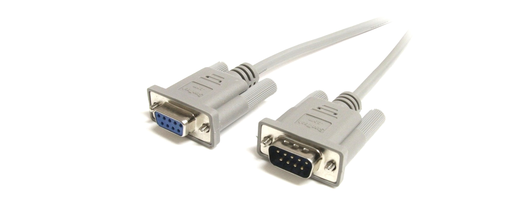
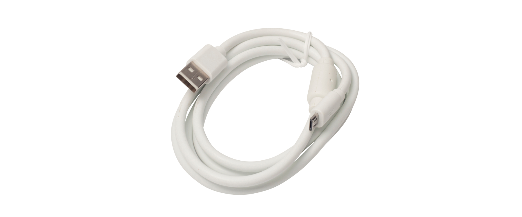
RS232 stands for Recommended Standard 232 and was introduced in 1960. It is a communication standard for serial transmission of data (think Morse code, more below). USB, on the other hand, stands for Universal Serial Bus and was introduced in 1996, and is the de facto industry standard for data transmission protocols.
Here is a comparison of RS232 and USB listing their advantages and disadvantages (see also a nice article on mouser.ca on how older communication standards still compete with USB):
RS232: simplicity over performance
|
|
USB: functionality over simplicity
|
|
RS232 basics: Baud rate & data protocol
So let's say you are convinced and would like to try to use RS232 in your next project to transmit or receive data. Great! What do you need to know about RS232? As it turns out, not very much.
First, in its simplest configuration that we will talk about today, RS232 only uses three wires to communicate. They are called TX (for ”transmit“), RX (for “receive”), and GND (which provides the ground potential reference). The RX and TX wires can carry positive voltage (which stands for a logical 0) and negative voltage (which stands for a logical 1), more on that below.
Second, we need to talk a bit about transmission speed. In the case of RS232, the transmission speed is commonly referred to as the BAUD rate. It counts how many transitions from 0 to 1 and vice versa occur per second, so it can be interpreted as a frequency of some sort. In practice, people tend to just say “1000 Baud” (or “1000 Bd” for short), or something to that effect, and use the unit Baud. There is a simple thing to remember:
- The faster the Baud rate, the more data you can transmit or receive.
- The faster the Baud rate, the more errors happen during transmission or reception.
You see: maxing out the Baud rate is not always the best idea. For our concrete case, a Baud rate of a few thousand is typically enough.
In this tutorial I want to focus on a very basic implementation of RS232 that allows you to transmit eight bits at a time. Here is how a typical RS232 signal looks like:
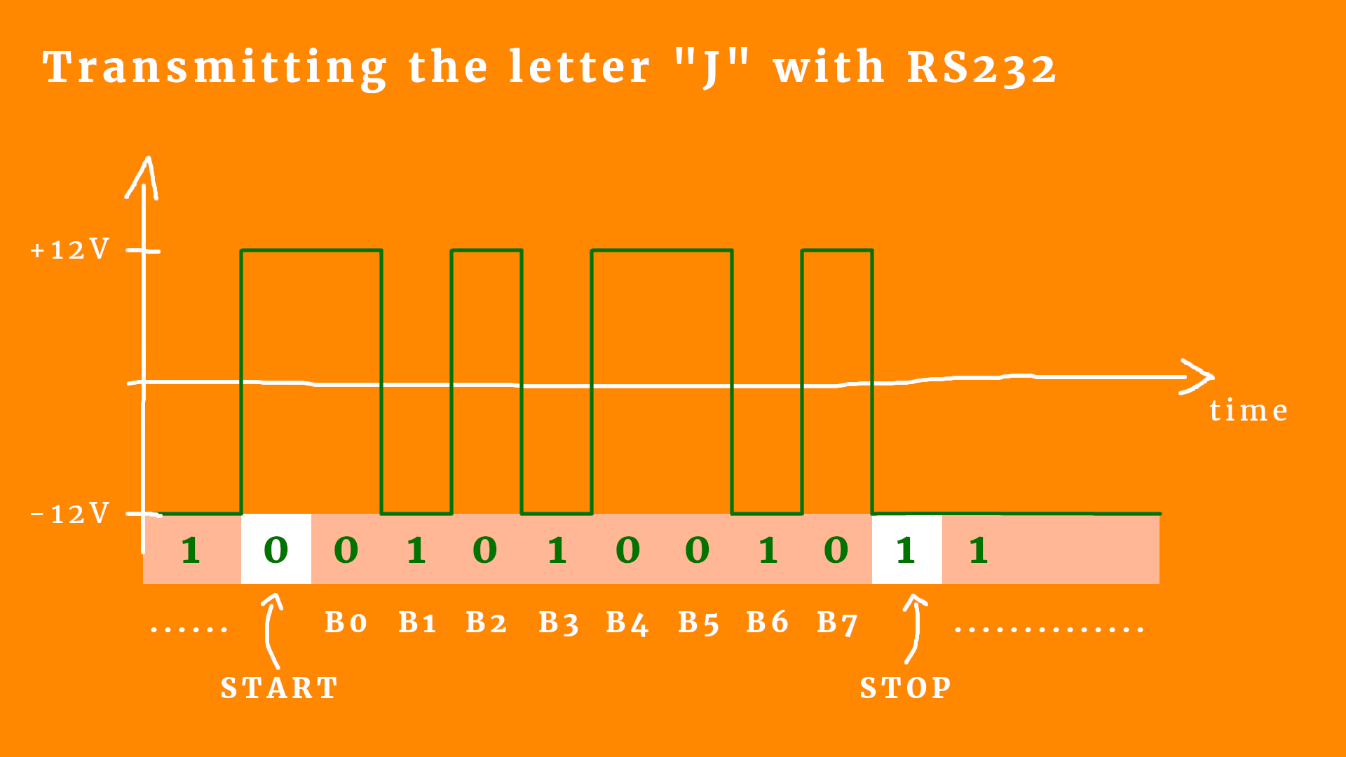
Okay, let's try to unpack this one bit at a time (pun 100% intended):
- A logical 1 is -12V, and a logical 0 is +12V. That's just how the protocol is defined :)
- The normal state, when nothing happens, is also called the idle state and I displayed it as a lot of dots (......) in the diagram. When nothing happens, the data line is at a logical 1.
- When a transmission starts, the data line goes to 0 for one period. We call that the start bit.
- Then follow the data bits, eight in our case. It starts with the least significant bit and ends with the most significant bit. If this confuses you, go check out my tutorial on binary numbers :) In a nutshell: RS232 sends a binary number from right to left. If you have the number 0b01001010 it will send the bits 0,1,0,1,0,0,1,0, which is from right to left.
- At the end follows the stop bit, which is always a logical 1.
- And then we go back to the idle state (meaning a logical 1) until the next data is sent.
I think it's important to point out that none of this works if we don't specify the protocol to the receiver! The receiver has to know what the Baud rate is, because only then they can distinguish between receiving a logical 1, or maybe 2 of them, or 3 of them. But yeah, that's the basic idea of RS232!
If you are interested and want to learn more details about RS232 (we only scratched the surface here) I highly recommend the excellent article on the RS232 protocol by CircuitDigest.
Terminal programs
Okay, there is one thing missing. Say you have a circuit that receives data via RS232. How can you send that data to the circuit? How could you debug it? Or, if it is the other way around and you have a circuit that sends data, how can you make sure that the data is sent correctly?
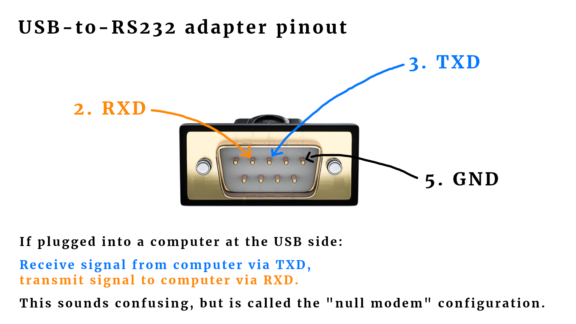
The answer is simple: you need a so-called terminal program. Those programs are simple pieces of software that monitor the RS232 connection of your computer. If your computer does no longer come with a dedicated RS232 connector you can use a USB-RS232 converter as shown here:
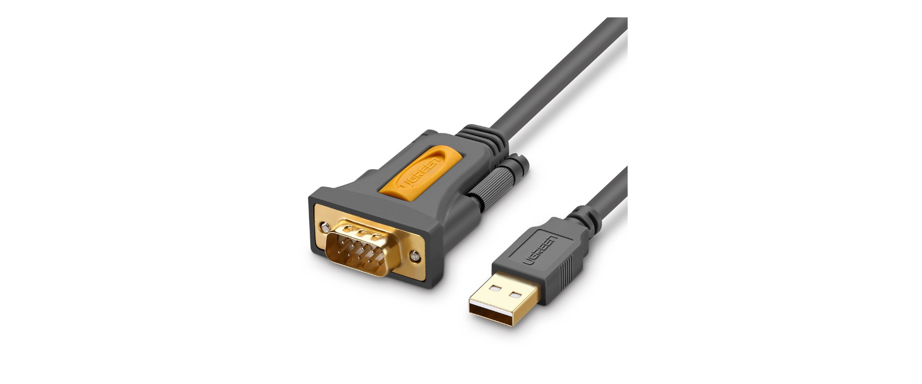
These adapters emulate a virtual RS232 serial port via USB and are usually plug-and-play. After plugging those into your USB port, your computer will think that it has a regular serial port. Magic! In included a link to such an adapter in the resources box.
And now it is time to start the terminal program. If you do a quick Google search for “RS232 terminal program” you will find many results, all of them typically work quite well. Here is a list of possible choices:
- Termite: a simple RS232 terminal
- RealTerm: Serial/TCP Terminal
- com port development tool
- HTerm 0.8.1beta
In what follows, I will focus on using HTerm (which comes from a German developer but whose GUI is entirely in English, so don't be afraid). You can download the software for both Windows and Linux in the resources box. Here is how it looks like:
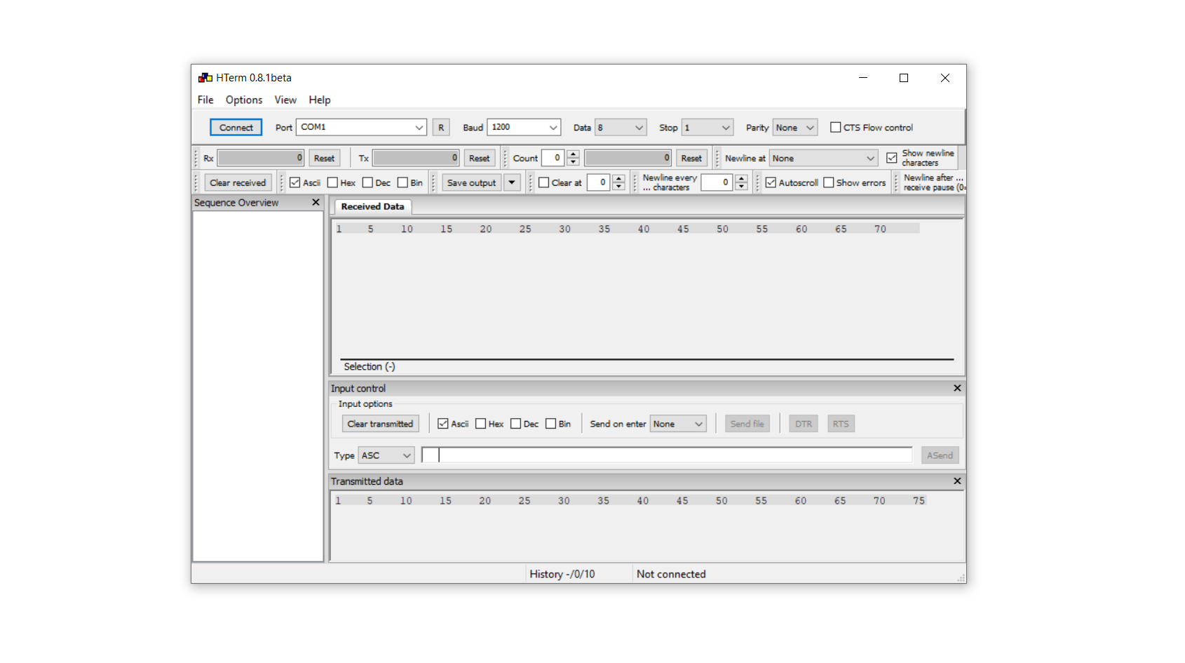
In the context of microcontroller communication, I find the following settings useful:
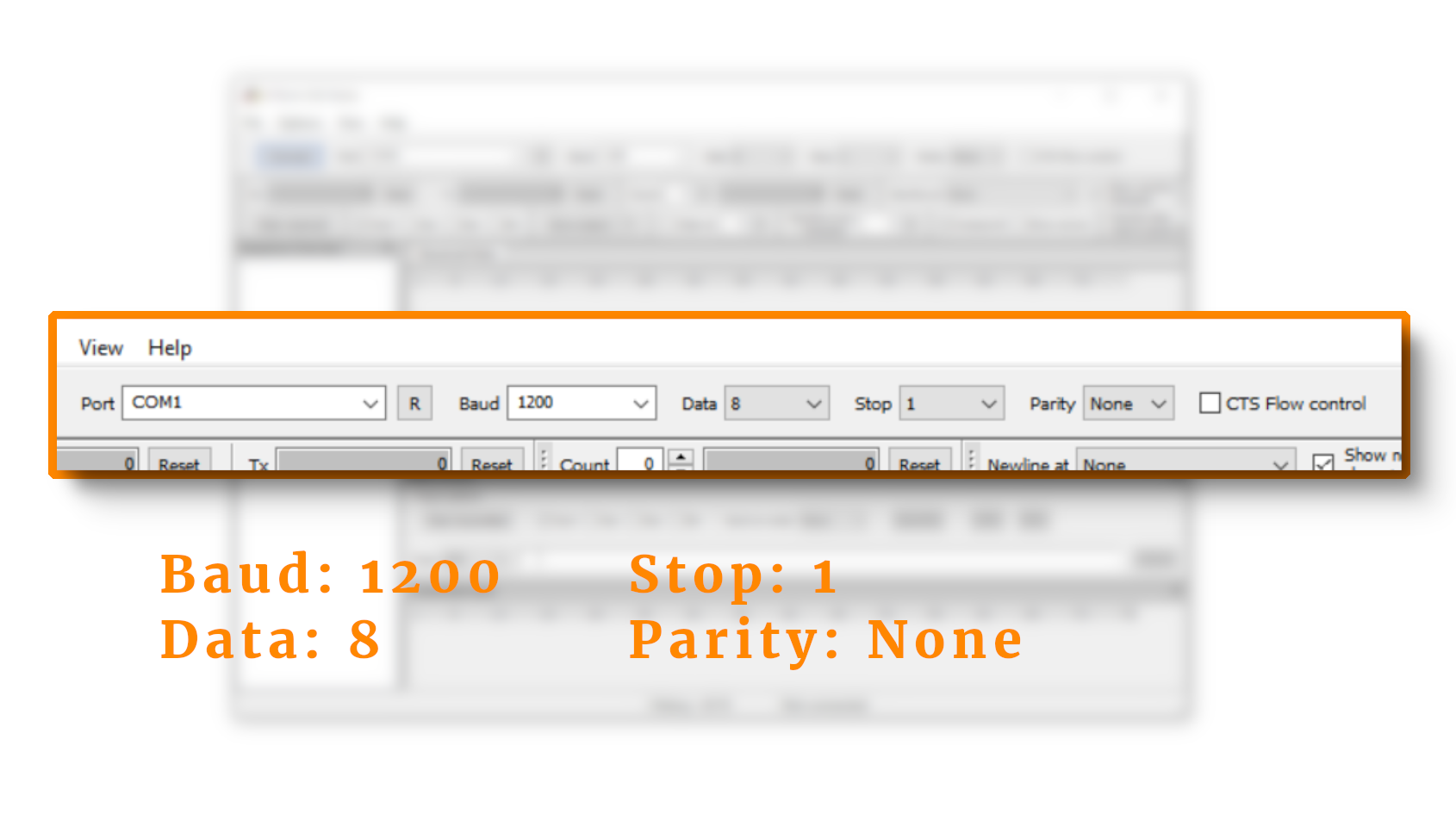
- Baud rate 1200. This is quite slow but fast enough for our purposes. It corresponds to around 120 bytes per second which I consider plenty.
- 8 data bits. I chose this option because it is helpful for transmitting characters in the ASCII format. In this format, each number from 0 to 255 corresponds to a certain symbol. For example, the letter “A” is 65, and the letter “a” is 97.
- 1 stop bit. I won't go into detail here, but this is a fairly standard setting.
- Parity: None. Parity can be used to make sure the transmitted data does not contain any errors. We don't need this extra level of complication here because our Baud rate is very low and therefore it is quite unlikely to get transmission errors.
- These settings can be abbreviated by the shorthand notation b:1200 d:8 s:1 p:None.
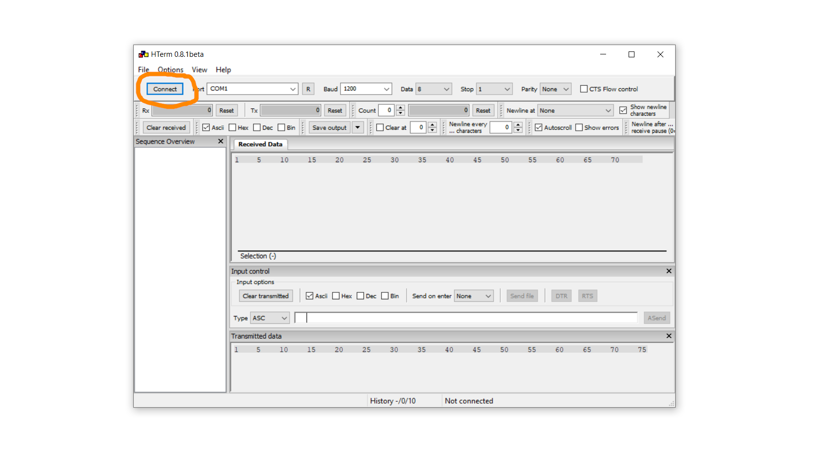
And that is all we need! Now we can click on Connect and establish a connection to the RS232 port (which is called “COM1” in my case and may have a different name in yours).
Then you can simply type a sequence of letters (and this works well because we selected 8 data bits):
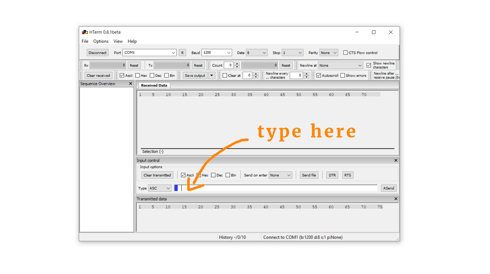
Then just press enter (or return) and the data is sent to the RS232 port:
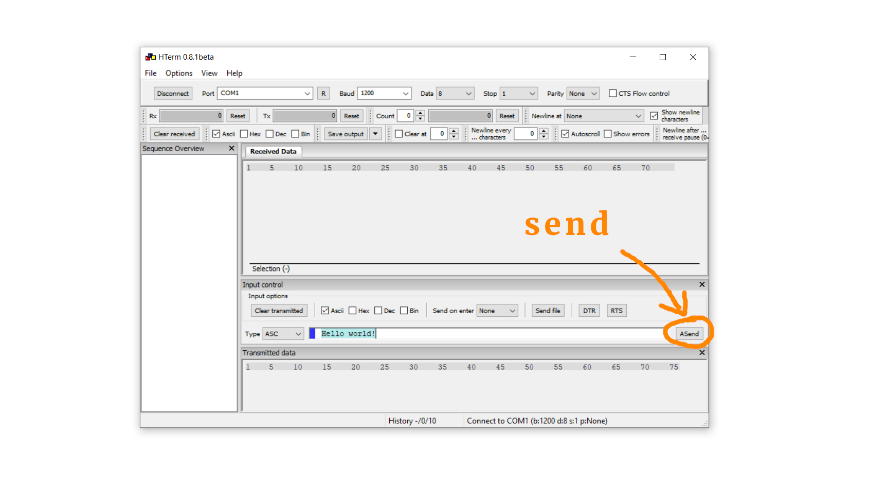
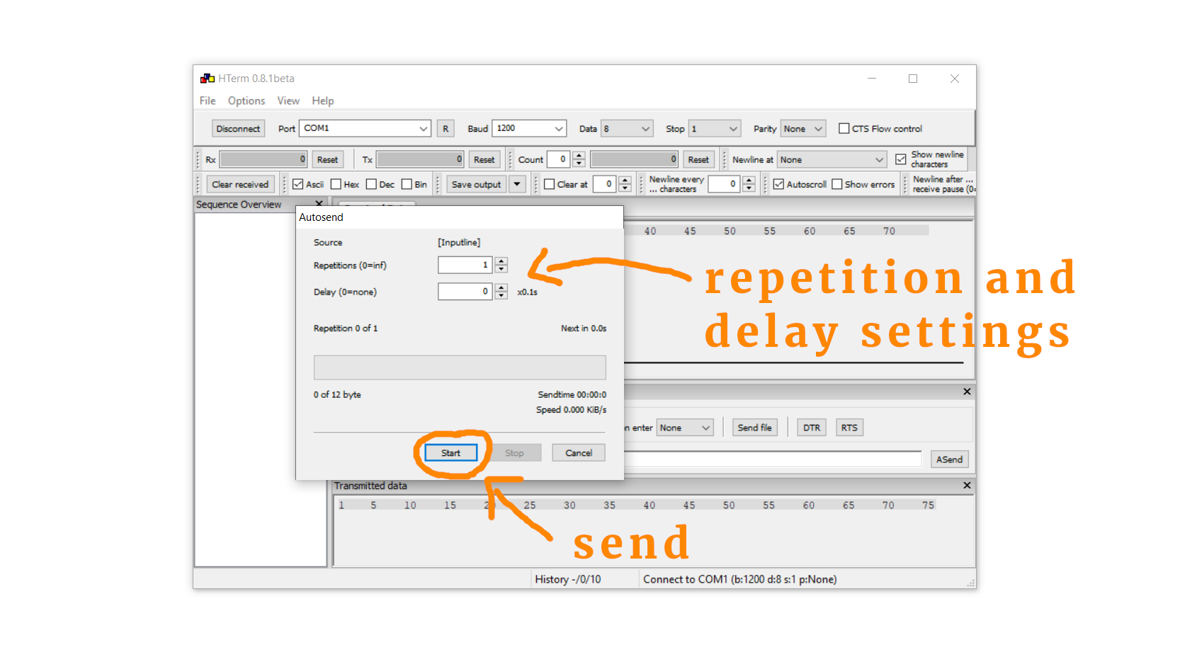
Congrats! Your text has just been sent! Alternatively, you can also click on ASend, and then a window will pop up that allows for repetition and delay settings. If that's what you want, input the data and lick on Start.
OK, so now what? Let us now finally talk about how to configure your PIC controller so that it can listen to the RS232 data that we just sent!
Configuring your PIC's USART module
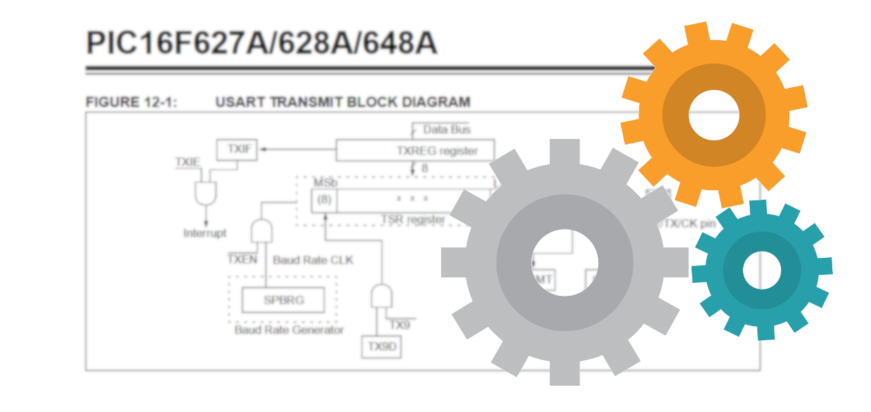
As we said above: now it's time to choose a PIC microcontroller and configure it so that it can transmit and receive RS232. For the sake of this tutorial we will focus on the PIC16F627A microcontroller whose datasheet you can find in the resources box, but all of these steps have their counterpart with other PIC microcontrollers.
All microcontrollers you ask? No, that's technically not true. Only microcontrollers with a so-called USART module can make use of RS232. USART stands for Universal Synchronous-Asynchronous Receiver Transmitter. Yeah, that's a mouthful.
Well, we understand the receiver/transmitter part, and the “universal” means that it can also be used with slightly different protocols from RS232. The “Synchronous” and “Asynchronous” refers to the way the data is sent and received. We will focus here on the asynchronous mode. This is convenient because we can just send some data to the USART module and it will send it automatically (like a magic black box), and we can receive data similarly. I hope it will become clear below!
Overall, there are the following registers associated with the USART module of the PIC16F627A:
- BRGH: 1 for high Baud rates, 0 for lower Baud rates
- SPBRG : set the Baud rate
- SYNC: 1 for synchronous, and 0 for asynchronous mode
- SPEN: enables the serial port
- RCIE: triggers and interrupt when something is received
- CREN: enable receiver mode
- RCIF: interrupt flag for reception of data
- RCREG: contains the received data
- TXREG: contains the data you want to send
- TXEN: send data
As you can see, it is a bunch of stuff. Instead of going into a lot of detail on all the possible configurations let us focus on a concrete application. We want to do the following:
- Initialize the USART in asynchronous mode with a Baud rate of, say, 1200.
- Create a software routine that checks if some data has been received.
- Create a software routine that can send some data.
Let's start simple and set up the USART module. Here is the code:
BRGH = 0;
SPBRG = 51;
SYNC = 0;
SPEN = 1;
In the first line we tell the controller that our Baud rate is rather low (1200 is very low indeed). Then, in line 2, we set the Baud rate to 1200. The value of SPBRG is related to the Baud rate as follows:

Given a target Baud rate of, say, 1200, we can recast this formula and solve for SPBRG:

If we run the PIC with its internal oscillator, the oscillator frequency fosc is equal to 4MHz. If you use a crystal, the value of fosc will be given by the oscillation frequency of the crystal. At any rate, inserting 4000000 (which is the oscillation frequency in Hertz) into the above formula gives a value of 51 for SPBRG. The Baud rate is not exactly 1200 this way, but it is close enough since the tolerance of the RS232 protocol is 5%. In line 3 we set the USART module to the asynchronous mode, and in line 4 we finally turn the USART module ON.
Okay, now what happens if we want to react to data that was sent to us? This is how we can do it:
RCIE = 1;
GIE = 1;
PEIE = 1;
CREN = 1;
In line 5 we tell the controller to trigger an interrupt whenever a character is received. If you want to learn more about interrupts check out the article on interrupts here. In lines 6 and 7 we turn on the global interrupts and peripheral interrupts. This is required, because if these bits are not set then the PIC will simply ignore line 5. Last, in line 8, we turn the receiver module ON.
And then we also need to specify the interrupt service routine (isr) that is called whenever a character is received. Here it is:
void __interrupt () isr (void) {

  // received some data?
  if (RCIF) {

    // retrieve value
    value = RCREG;

    // react to possible errors (we skip that here)
    CREN = 0;
    CREN = 1;
    OERR = 0;
    FERR = 0;

	// send value back to computer
	TXREG = value;
	TXEN = 1;

  }

}
In line 4 we check if we have indeed received data via RS232. This is necessary because the interrupt service routine is called for any interrupt, and if our software becomes more complicated and uses multiple interrupts we need to make sure that the correct interrupt flag is set. In this case, we need to check if data has been received, which is exactly what line 4 accomplishes.
In line 7 we can retrieve the value that was sent, and in lines 10–13 we reset all errors. This is potentially bad programming style, since a reasonable software should check if there are any reception errors. Again, since we are using very low Baud rates, I never encountered any problems. If you use higher Baud rates, you might want to refer to the datasheet to check for specific errors. And that's it!
And then, in line 15–17, we send the value that we received back to the computer. It is very simple! Because we sent the mode to asynchronous, all we have to do is write the value to the TXREG register in line 16. And then, in line 17, we just set the transmission enable bit TXEN to send the data. After the data has been sent, the bit TXEN will be set back to zero automatically.
And that's it! Overall I find it quite remarkable how simple it is to send and receive data. Because the PIC16F627A contains an USART module, it all works like a black box without us having to implement the RS232 protocol by hand, which is quite convenient. At the same time I find this approach low-level enough that we still understand, in principle, what is going on. If we were to use USB, the level of abstraction would be a lot higher.
Now we can think about the circuitry a bit more. How to we connect an RS232 cable to a PIC controller?
Talk RS232 to me! The MAX232 level shifter

We learned at the very beginning of this article that in the RS232 protocol a logical HIGH is represented by a negative voltage, and a logical LOW is represented by a positive voltage. It is clear that this is very different from the logic levels used by PIC controllers which interpret a logical HIGH as +5V and a logical LOW as 0V.
To translate between these two “interpretations” we need a so-called level-shifter. A very common choice is the MAX232 integrated circuit:
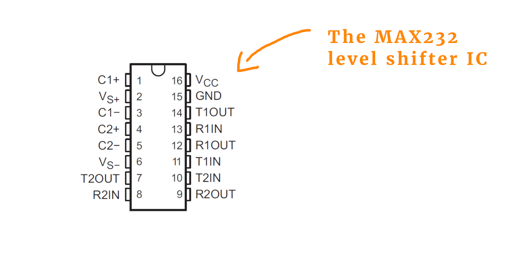
It is very simple to connect the MAX232 to external circuitry. All it needs are three external capacitors of 1μF:
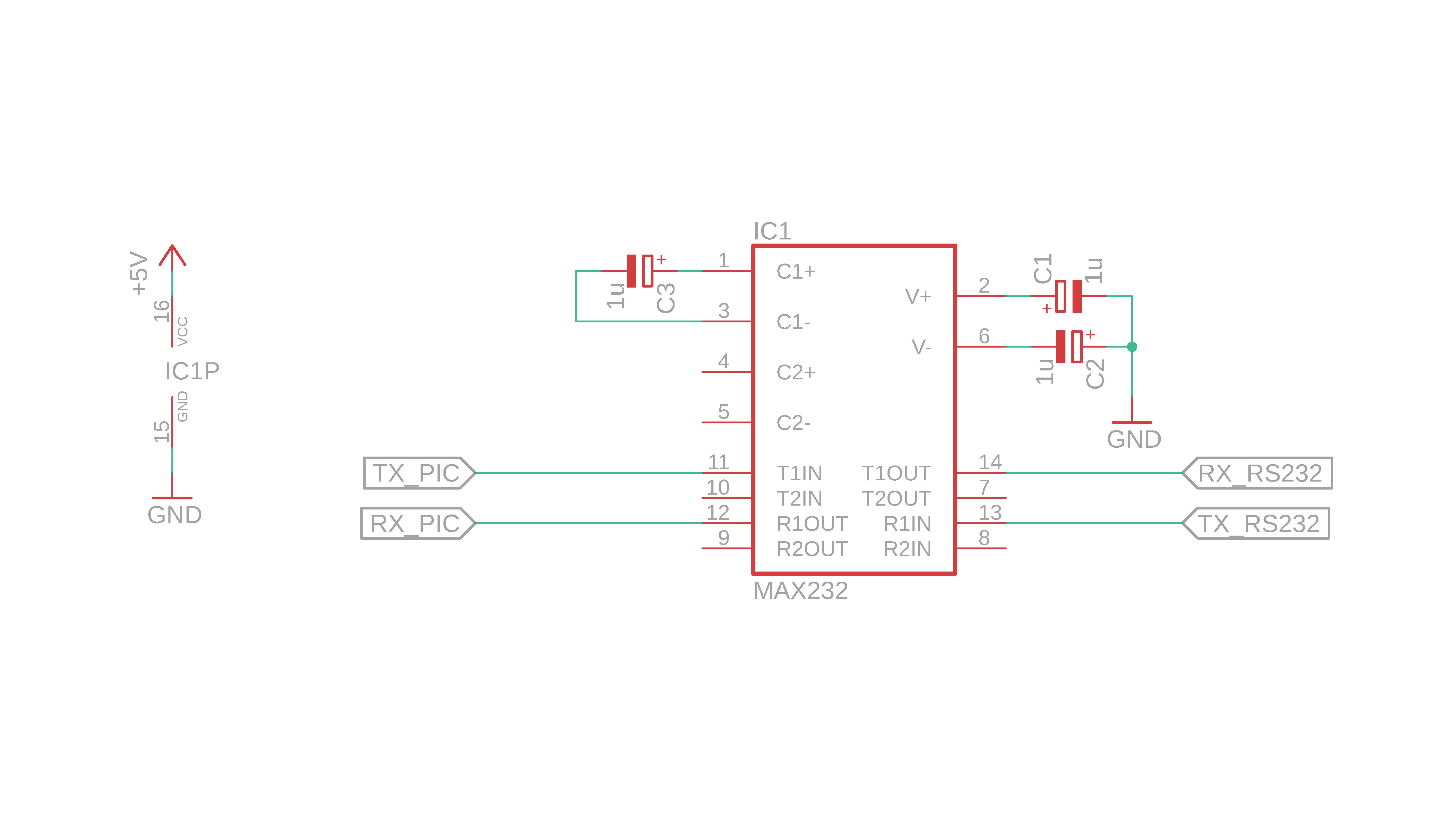
How does it work? It uses the capacitors as a so-called “charge pump:” The capacitors C1 and C2 get charged and GND is applied between them. This means that the MAX232 now has -12V and +12V at its disposal that it can use for transmitting data. For receiving data it is easier to shift it from negative values to positive ones since it only requires some resistors.
On the left you can connect microcontroller circuits, and on the right you can connect the RS232 connectors. Also, as you have probably seen already, the MAX232 offers two TX and two RX lines, respectively. If you use the other lines as well, you also have to connect a capacitor between C2+ and C2- (just like C3 is connected between C1+ and C1-). In our example we only need one, but in principle two PICs could share one MAX232 to connect to an RS232 connection. The symbol on the left just denotes the power supply for the MAX232. If you want to learn more about reading schematics check out our article here.
There is one very important detail. Look closely: on the right side, why did we connect T1OUT to RX and R1IN to TX? This is not a typo but completely intentional! Imagine these two scenarios:
- Some data is sent to the PIC. Where does it arrive at the RS232 side? On the TX line of course. If the PIC should receive that message, we need to connect it to the RX side on the PIC side :)
- Same goes for sending! If the PIC wants to send something, it does it via the TX line. But whoever is listening on the other side of the RS232 connection will look to the RX input.
For this reason we have to switch RX and TX whenever two computers, two PICs, or a computer and a PIC communicator with each other. This is super important. Why is it so confusing? When RS232 was first devised in the 1960s, it was developed as a means of communication between a computer and a modem. Nowadays, however, it is mostly used as a connection between computers. Because this way does not use a modem it is often called zero modem or null modem connection.
Truth be told: when I first built the circuit we are about to build together here, I messed it up. Only then I remembered what I just explained to you above :)
Control eight LEDs with RS232!
Now, after reading all that stuff, we have to reward ourselves by building a cool example circuit that allows us to test all that new stuff! Let's learn how to use RS232 to control eight LEDs on a breadboard with our computer!
The idea is very simple: if we send one byte via RS232 from the computer to the PIC, that's eight bits. Each bit represents one LED. If we send 255, all LEDs should turn on. If we send 128, only the leftmost LED should turn on, and if we send 3, then the two LEDs on the right turn on. Do you see what's happening? We simply use the eight LEDs to display the eight bits we receive in binary :) And then, just for fun, we will send the byte we just received back to the computer.
Here is the schematic for this simple project:
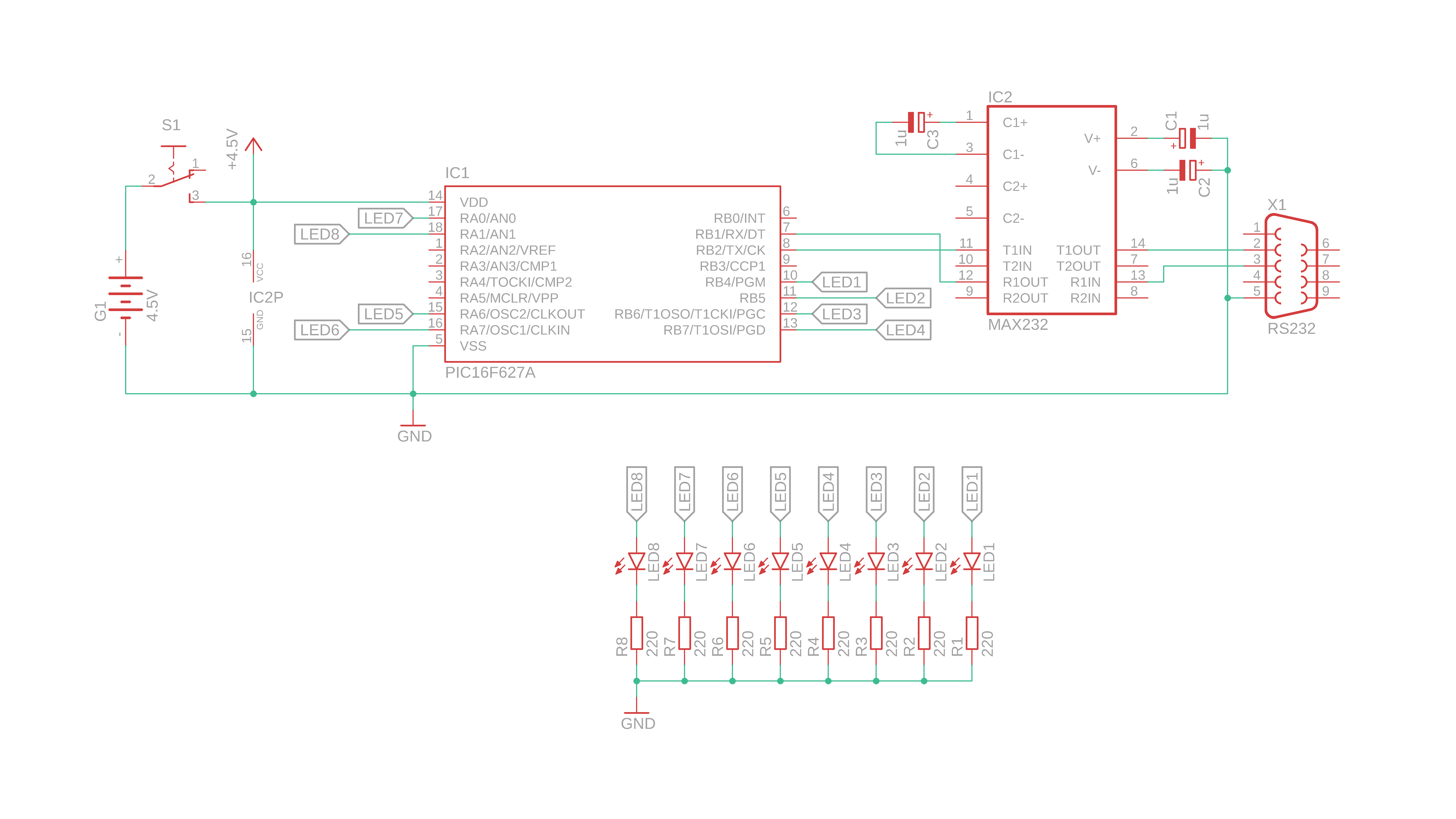
I hope that it's pretty straightforward. Let's look at it, as usual, step by step:
- The PIC16F627A is connected to +4.5V of the battery compartment G1 via a switch S1, and the MAX232 gets its power on pins 16 (VDD) and 15 (GND). That's what the funny looking symbol IC2P means.
- The eight LEDs LED1–LED8 are connected to some random ports. I used the ports so that it will be easy to build on a breadboard and not all crazy, but the choice is up to you of course :) Just remember to change the code (see below) if you change the location of the LEDs.
- The connection of the MAX232 is exactly as we already talked about above, no surprises there. Just remember the null modem wiring, and you're all set. More on that below!
Now that we understand the schematic (if you don't, get in touch on social media and we will figure it out) we can talk about the source code!
The source code
We already talked about most details above, so here I will only focus on how we display the received bit on the LEDs. The rest of the program is identical to what we talked about above. You can find a full listing of the source code in the appendix and can download the readily compiled .hex file in the resources box.
First, we need to tell the controller where the LEDs are connected. This is how we do it:
// define LED locations for later convenience
#define LED1 RB4
#define LED2 RB5
#define LED3 RB6
#define LED4 RB7
#define LED5 RA6
#define LED6 RA7
#define LED7 RA0
#define LED8 RA1
Then, we need to tell the PIC16F627A that the LEDs are outputs. And we need to set both the TX and RX pin of the PIC16F627A to the input mode:
// set tristate registers

// tristate bits for RB1 (RX) and RB2 (TX)
// must both be set to 1 in USART mode
TRISB1 = 1;
TRISB2 = 1;

// LEDs are outputs
TRISB4 = 0;
TRISB5 = 0;
TRISB6 = 0;
TRISB7 = 0;
TRISA0 = 0;
TRISA1 = 0;
TRISA6 = 0;
TRISA7 = 0;
Then follow to odd, but important lines: they turn off the analog features on PORTA of the PIC16F627A. Without that line we could not use some of the pins on PORTA as outputs for the LEDs.
// disable analog features on PORTA
// (we don't need them here)
CMCON = 0b111;
And then follows the configuration for the USART module that we already covered above. The interrupt service routine is also the same as above, and all that remains is the main loop:
// main loop
while (1) {

	// update LEDs
	LED1 = value & 1;
	LED2 = (value >> 1) & 1;
	LED3 = (value >> 2) & 1;
	LED4 = (value >> 3) & 1;
	LED5 = (value >> 4) & 1;
	LED6 = (value >> 5) & 1;
	LED7 = (value >> 6) & 1;
	LED8 = (value >> 7) & 1;

}
It's super simple, because all the difficult stuff (receiving the data, and sending it back for fun) is done automatically for us in the background. So the main loop, that is executed over and over and over until the Universe ends, only has to make sure to send the right values to the LEDs.
How does it do that? Each LED, from 1 to 8, corresponds to the bit of the same number. What does that mean? Take the number 84, for example, and imagine we send it to our circuit. In binary the number 84 is 0b01010100. This means that LEDs number 3, 5, and 7 have to turn on. This is exactly what each of the lines 91–98 do. They just check if their bit is set, or not. If it is, the LED turns on, and if it isn't set, the LED remains dark. If that kind of binary arithmetics confuses you, you can check out my tutorial on how to learn binary, and I hope it will be helpful :)
And believe it or not, that's all the code! Now we need to compile it in the MPLAB X IDE, and you can read all about it here, and that will spit out a .hex file that contains machine code, and now we can take that .hex file and upload, or “flash” it onto the PIC16F627A :)
Flashing the PIC16F627A
As always, we need to take the .hex file that we compiled in the previous section and flash it onto the controller. You need the PICkit3 and a computer that runs the freely available MPLAB X IPE. Check out the resources box for links on where to download MPLAB X IDE, and check the tools box on where to purchase the PICkit3. If you are a bit lost, consider checking out the article on how to flash a PIC :)
This is the little schematic we need to build to flash the PIC16F627A:
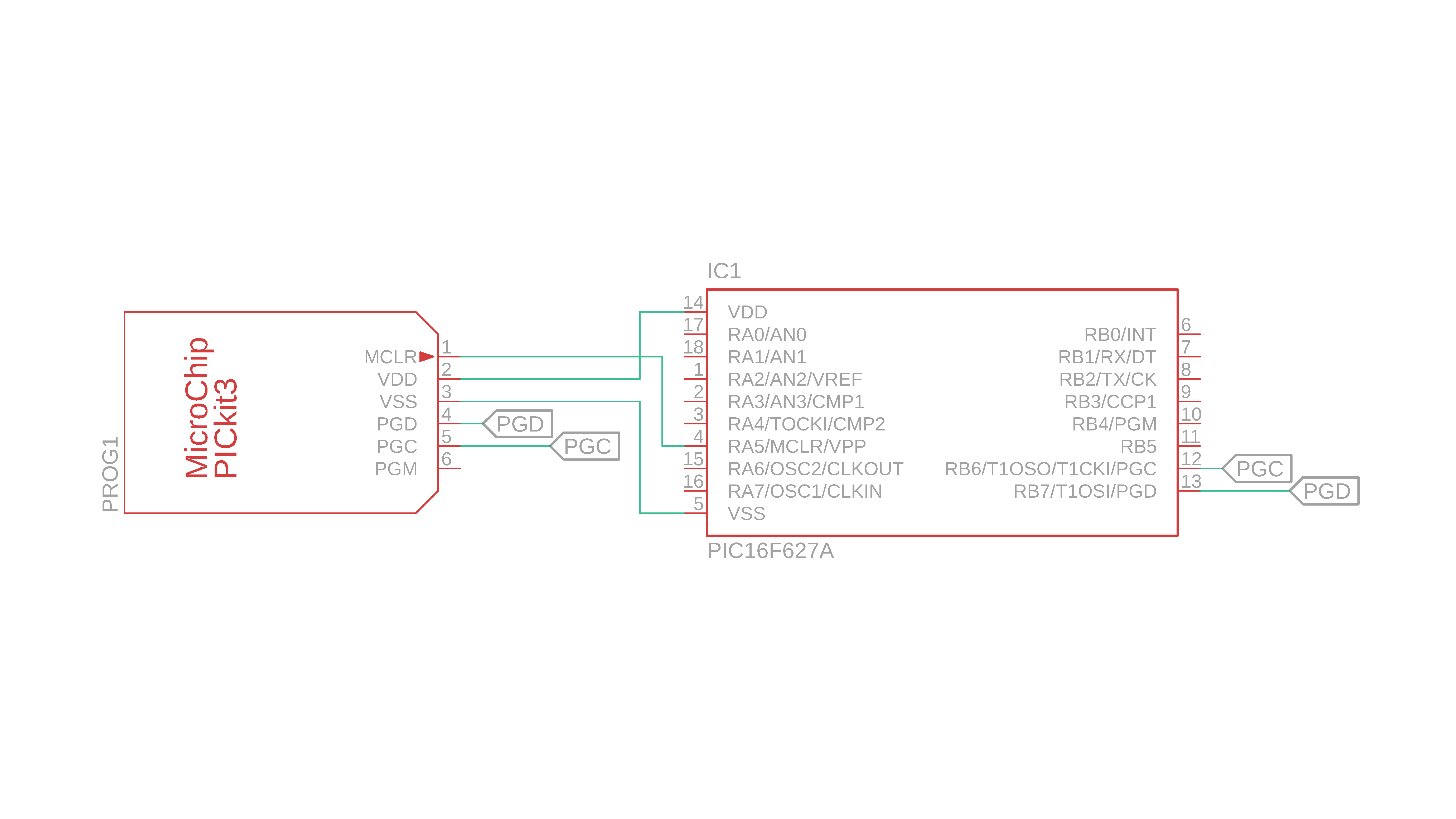
You need to build a circuit like this for any microcontroller project, but wiring it up is really not that complicated. This is how it looks like all done:
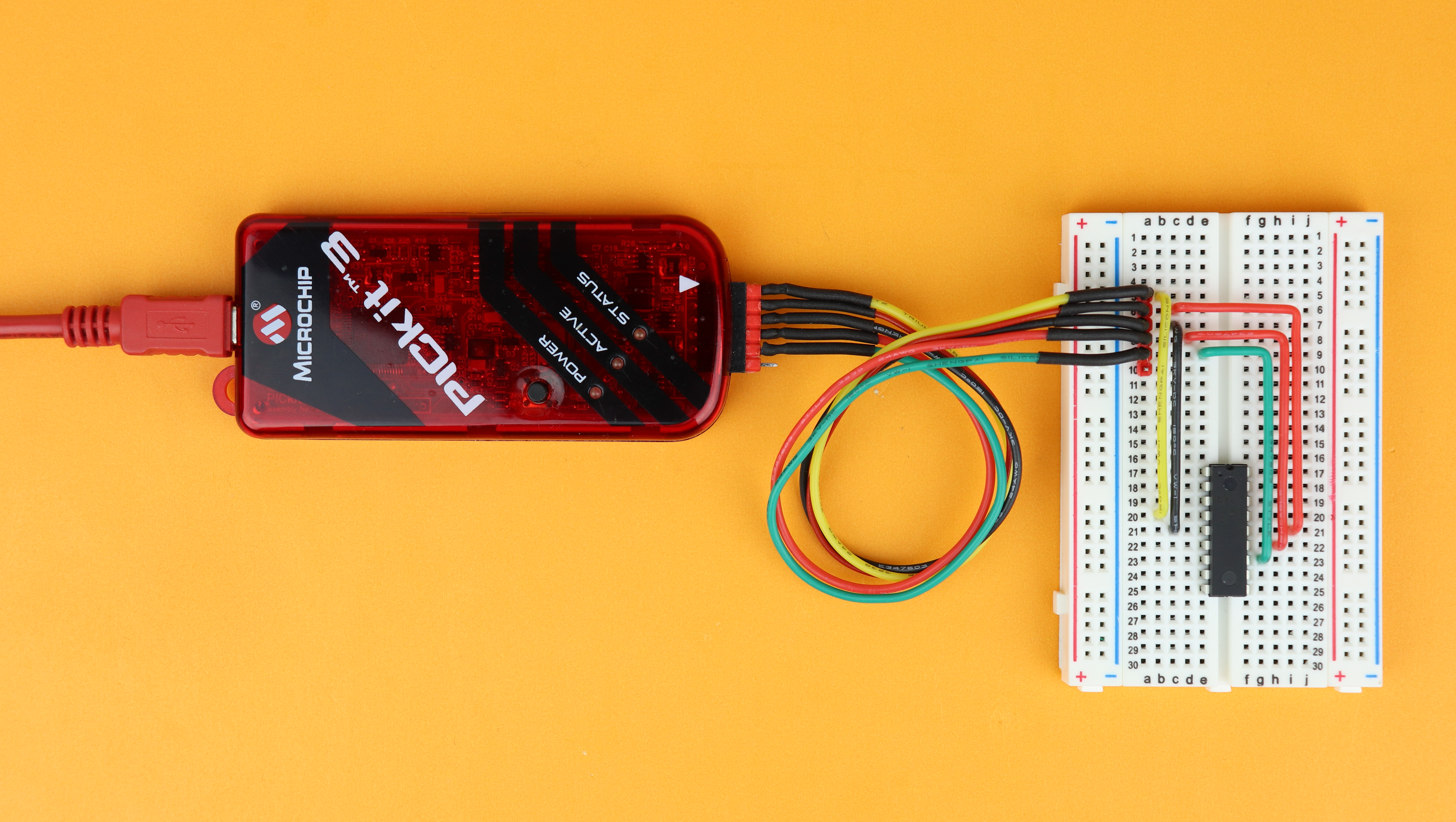
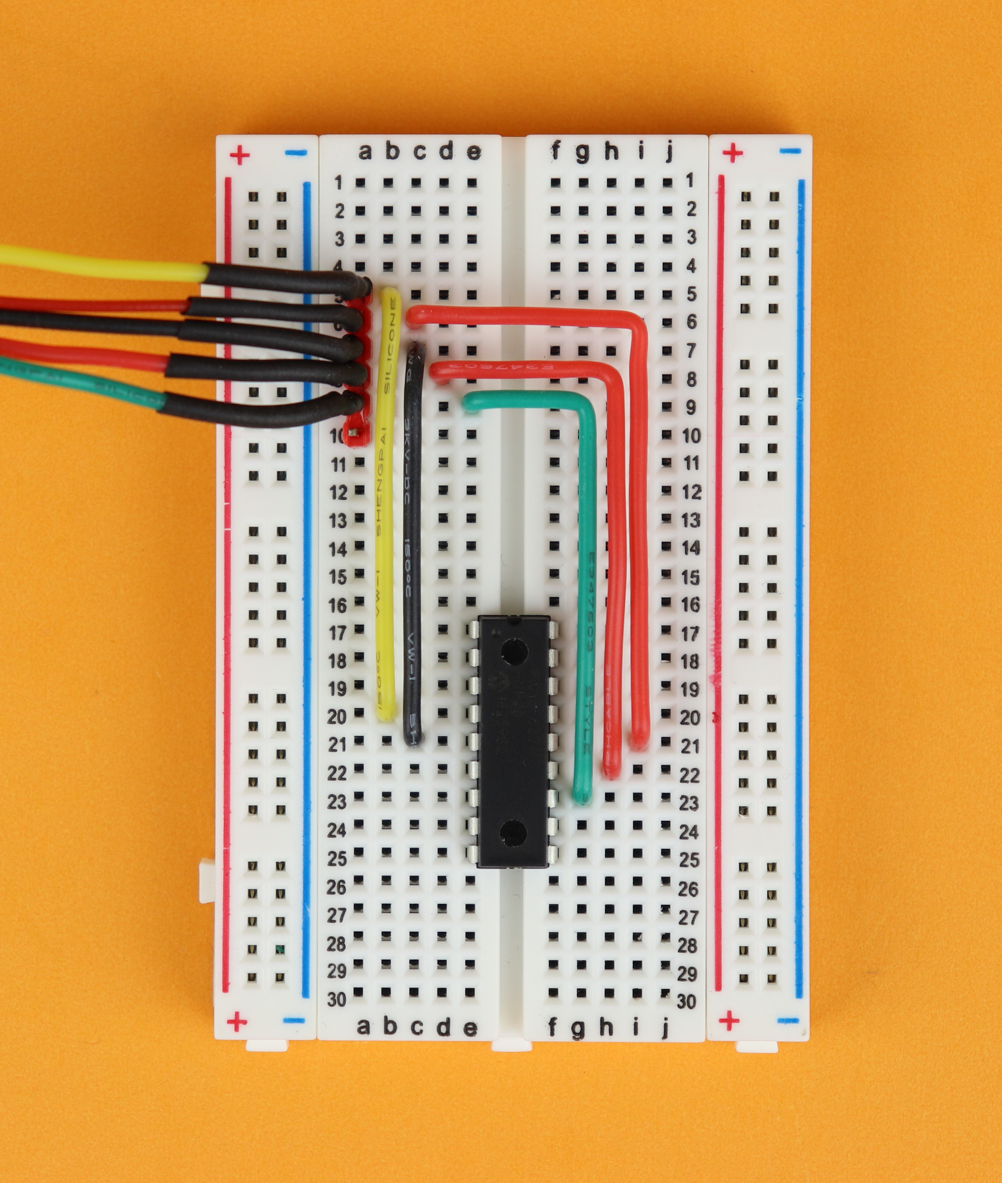
If that was too fast, here is a step-by-step guide on how to wire everything up for flashing:
-
-
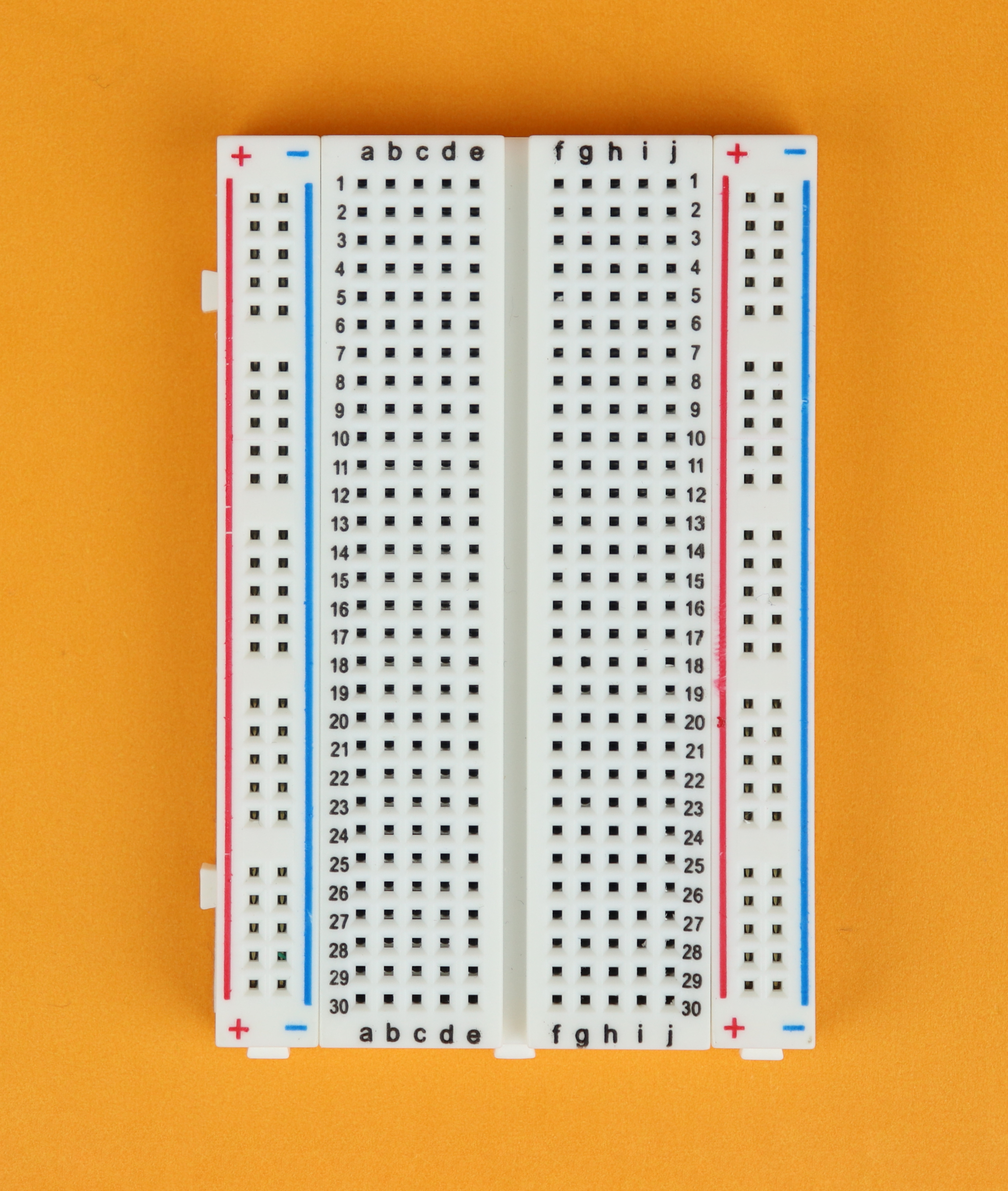
Step 1
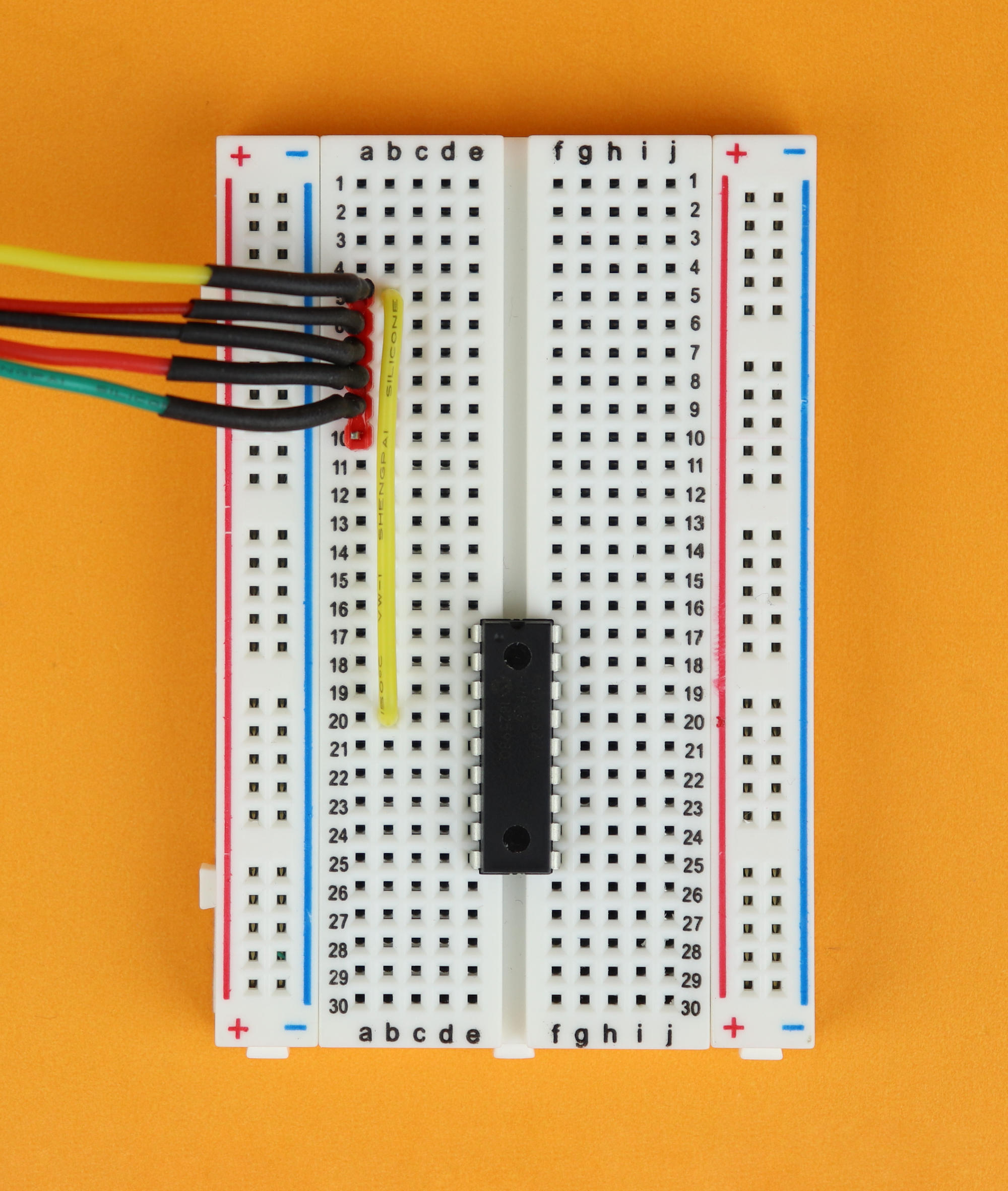
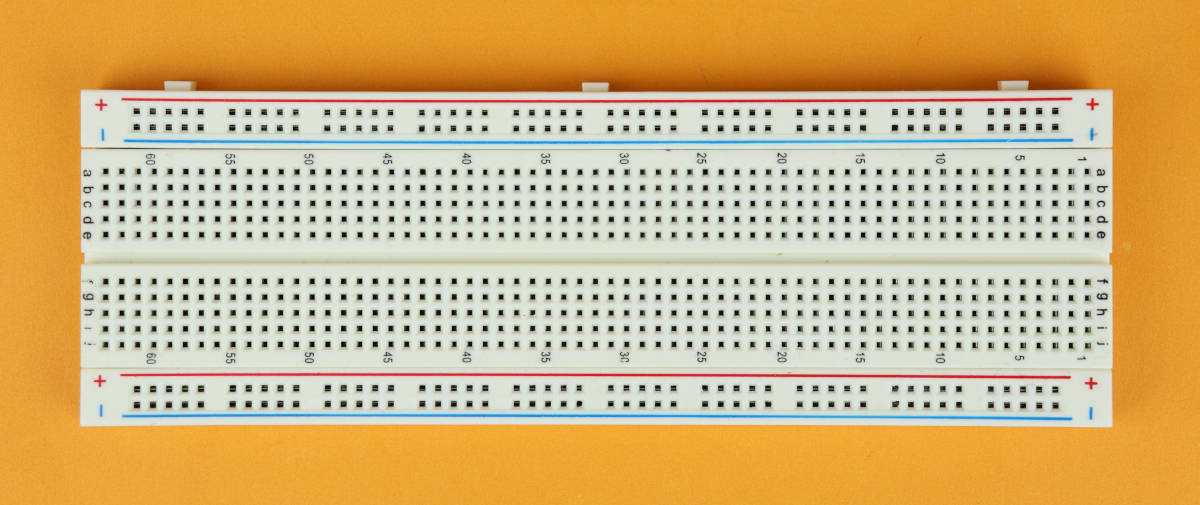
Place a 400-pin breadboard in front of you, and make sure that row 1 points to the top :) (You can also use the 830-pin breadboard that we will use for the main circuit of this tutorial.)
-
-
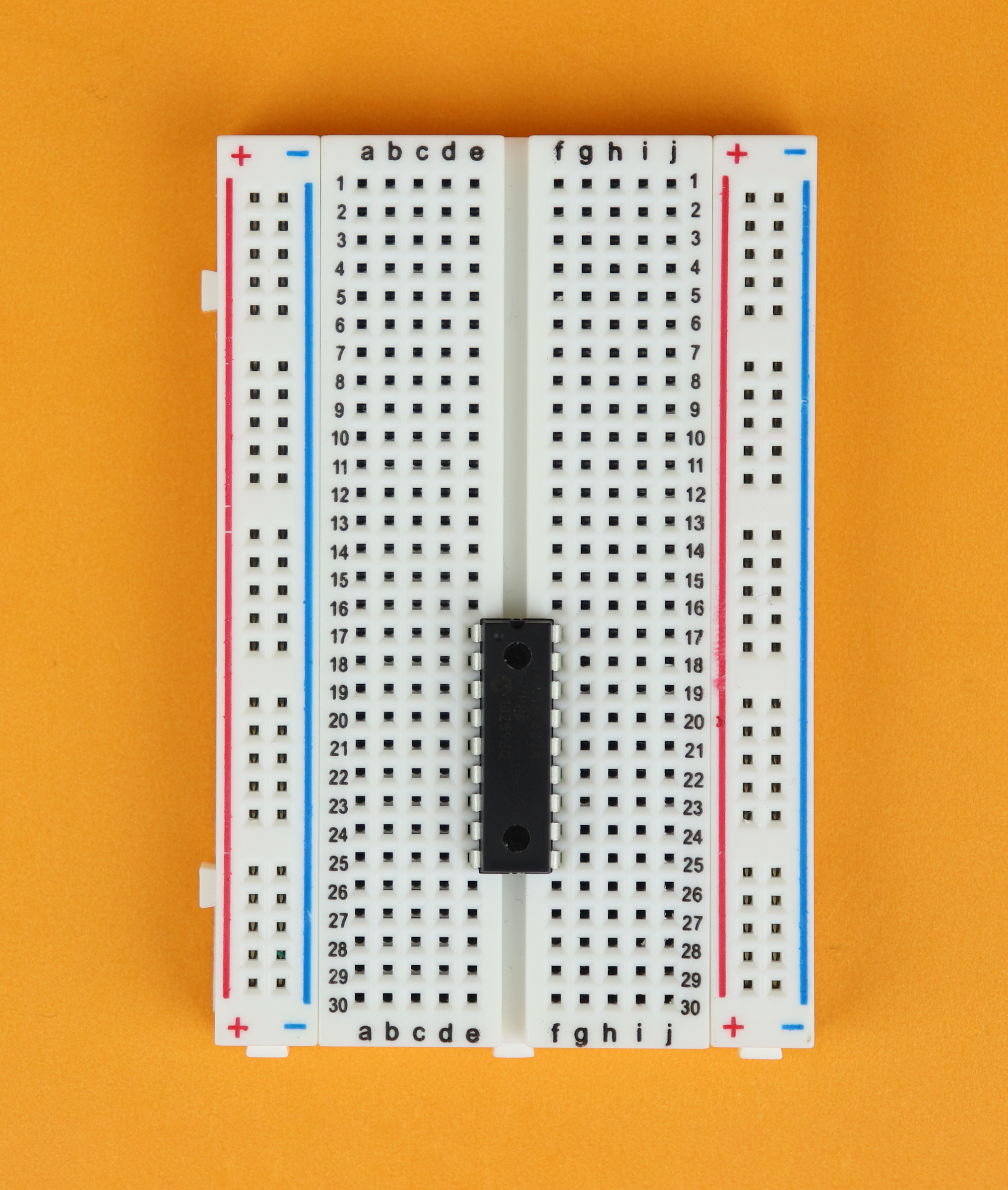
Step 2
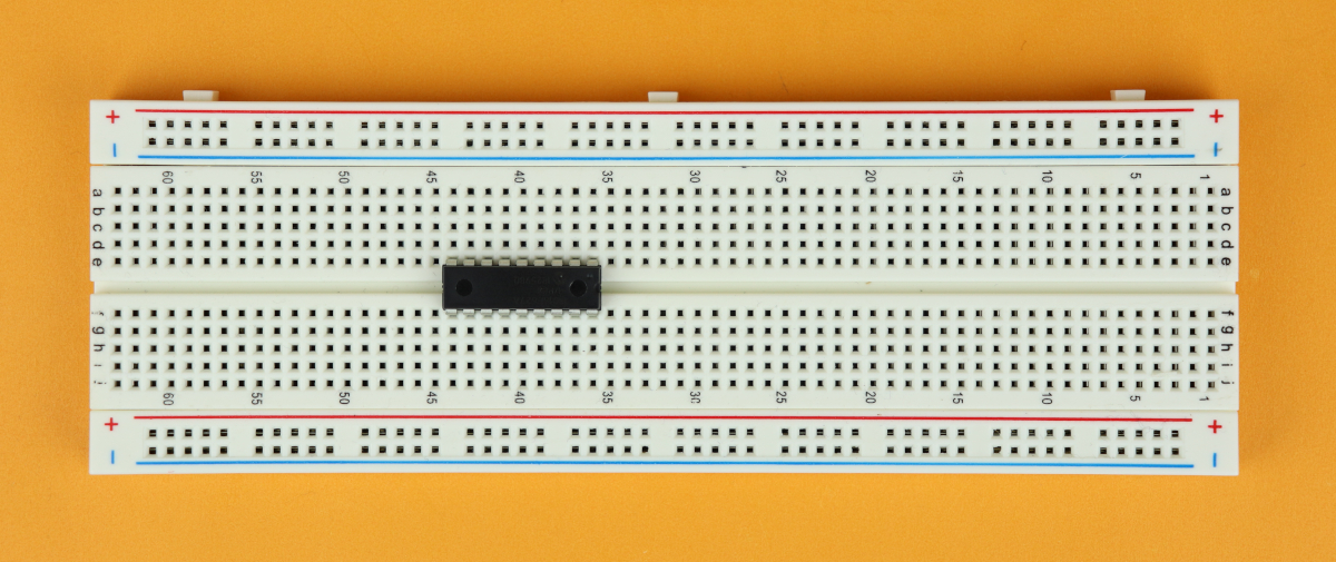
Place the PIC16F627A in row 17. Okay, it doesn't matter in which row you place it, but I placed it in row 17.
-
-
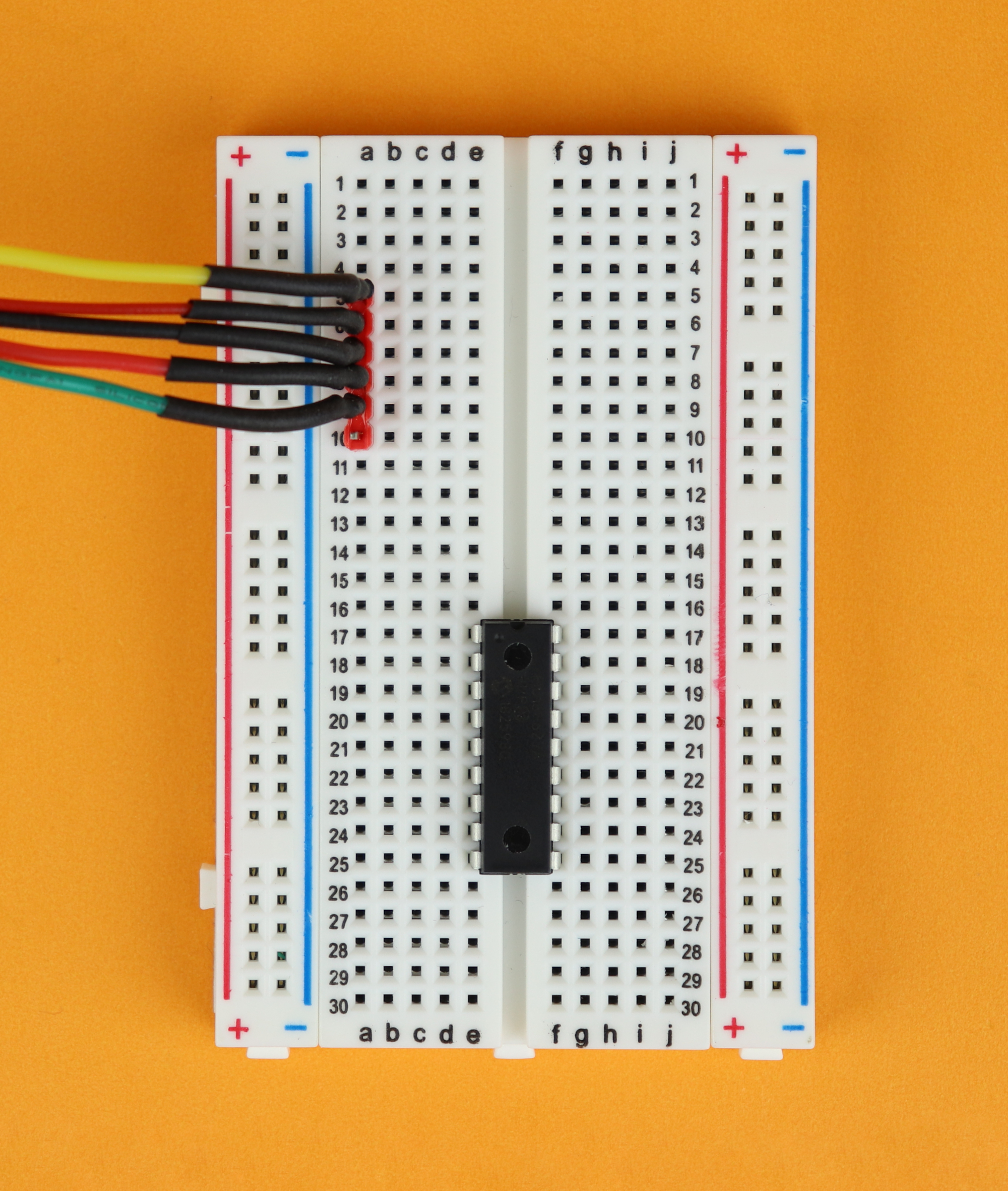
Step 3
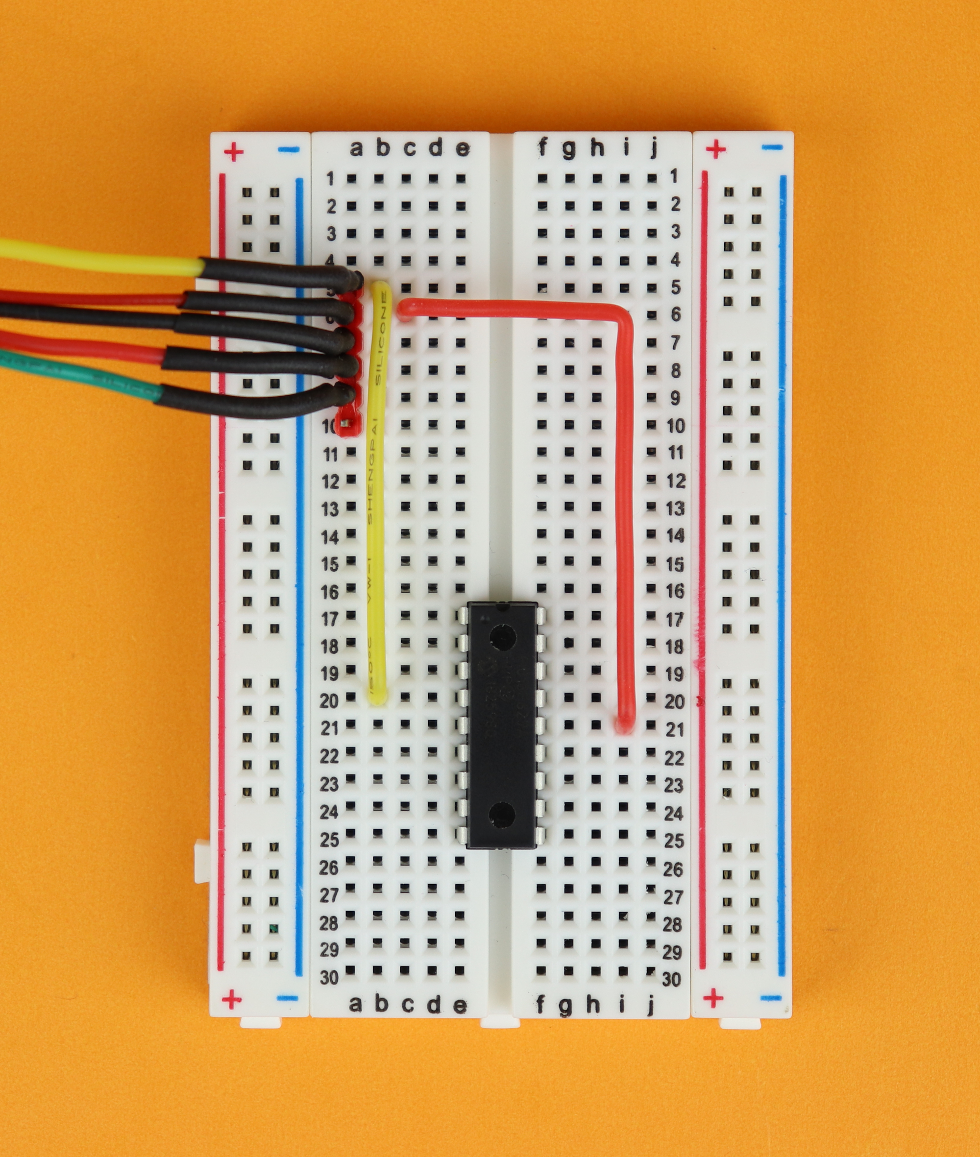
Insert the 6-terminal connecting cable to the PICkit3 in row 1, and make sure the MCLR cable (master clear) cable is in row 1.
-
-
Step 4
Connect MCLR (master clear) from row 1 at the PICkit3 connector to pin 4 of the PIC15F627A.
-
-
Step 5
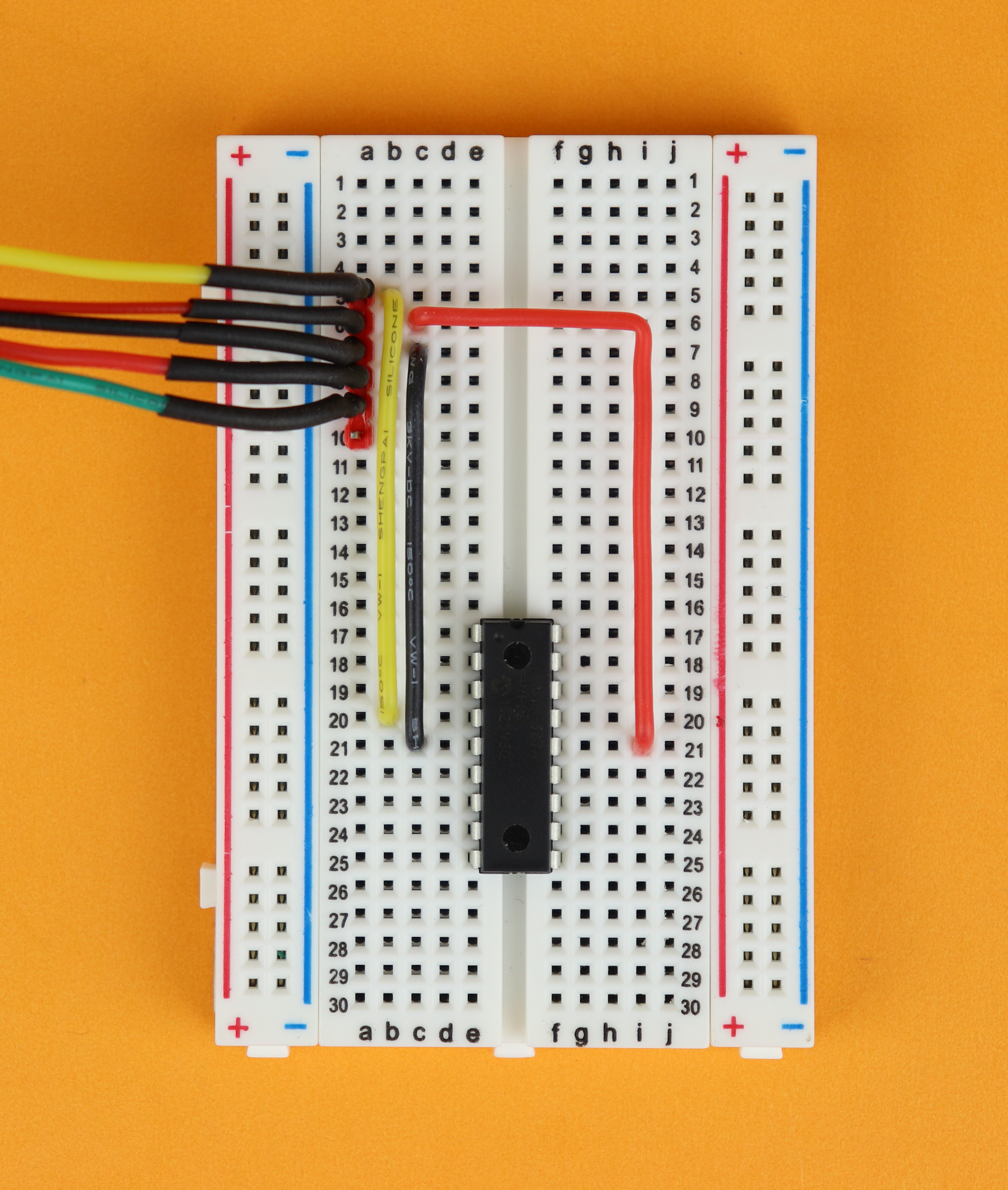
Connect VDD from row 2 at the PICkit3 connector to pin 14 of the PIC15F627A.
-
-
Step 6
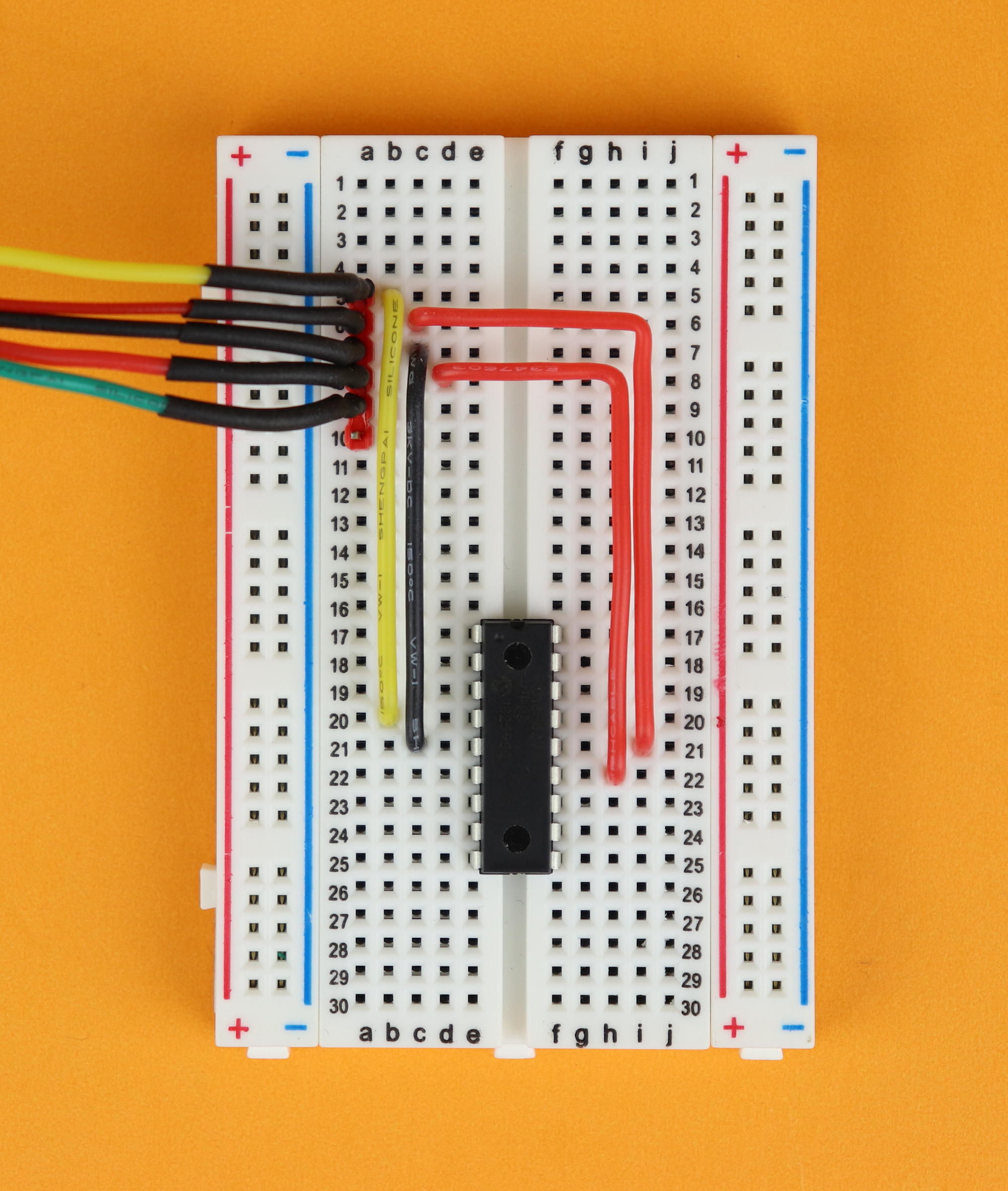
Connect GND from row 3 at the PICkit3 connector to pin 5 of the PIC15F627A.
-
-
Step 7
Connect PGD (programming data) from row 4 at the PICkit3 connector to pin 13 of the PIC15F627A.
-
-
Step 8
Connect PGC (programming clock) from row 5 at the PICkit3 connector to pin 12 of the PIC15F627A.
Building the circuit
Alright, after flashing the .hex file onto the PIC16F627A, we can now start building the schematic, step by step :) First, let's wire up the RS232 connector.
-
-
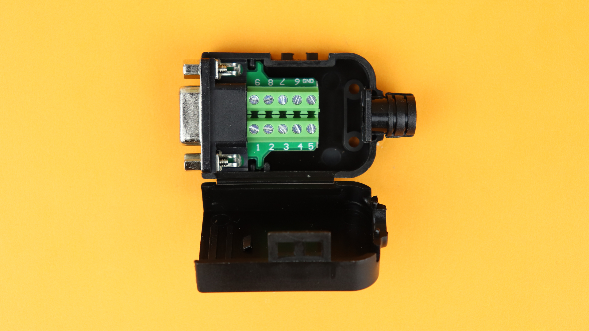
Step 1
Place the connector in front of you, and open it up with a screwdriver. Inside there is a PCB that has numbered connecting terminals, and those numbers are the same as in the schematic above.
-
-
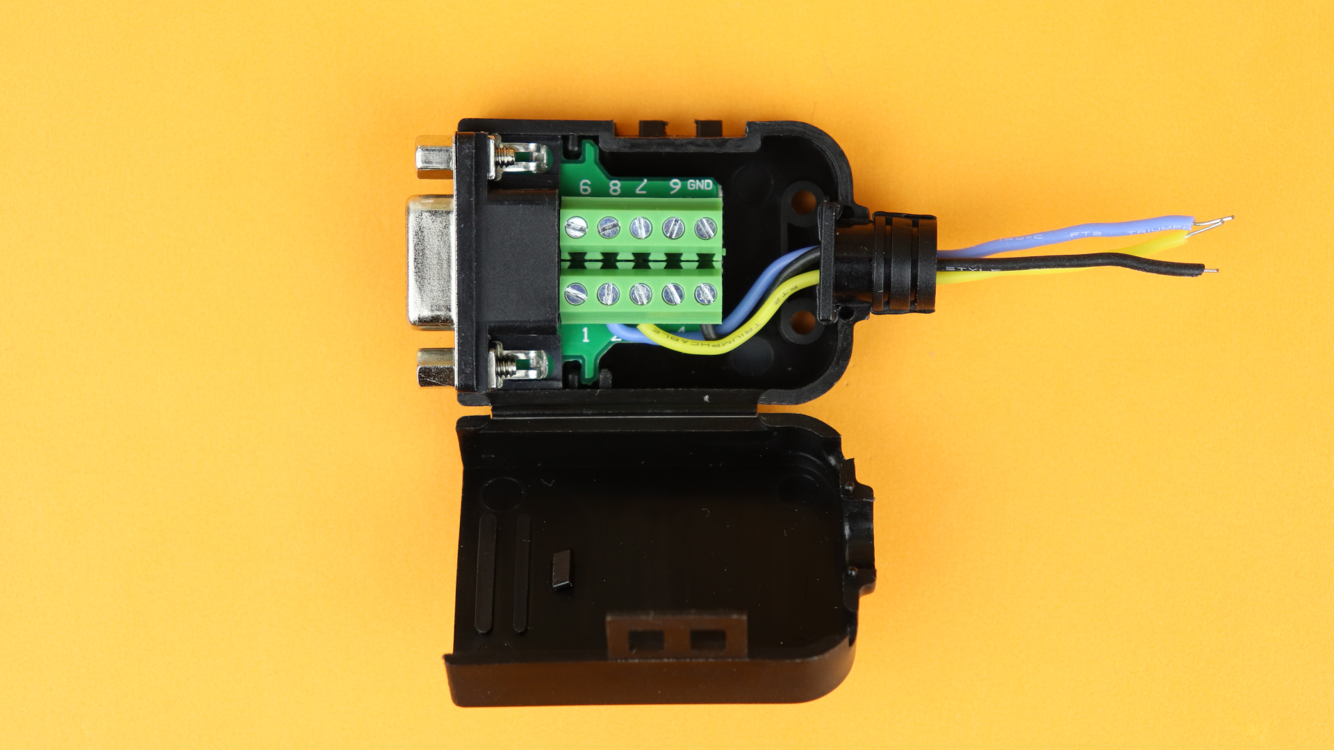
Step 2
Connect the blue TXD cable to terminal 2, the yellow RXD cable to terminal 3, and the black ground cable to terminal 5.
-
-
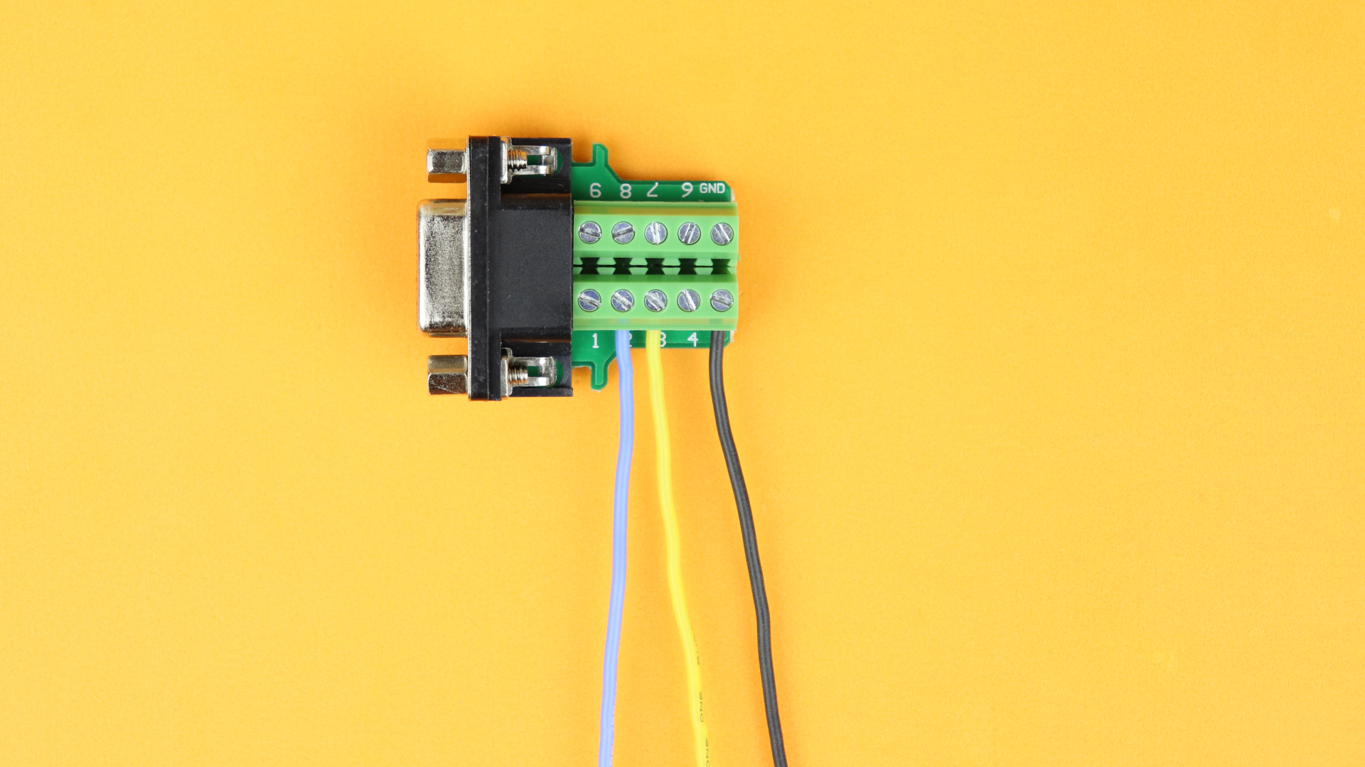
Step 3
Put the rubber strain relief back on and bend the wires carefully so that they come out at the back. Be careful not to pull the wires out of the terminals.
As we already mentioned above, we are working in the null modem configuration, so we need to switch the TX and RX lines somewhere. Looking at the schematic you can see that we wired up pin 2 of the RS232 connector to TXD (that's that T1OUT stands for) and pin 3 of the RS232 connector to RXD (called R1IN on the MAX232). On the RS232 cable that comes from the computer, however, the pins 2 and 3 are connected the other way around:
Long story short: if you connect the blue wire in the pictures above to T1OUT and the yellow wire to R1IN, all is good :) But don't worry: if you get it wrong, and nothing works, just switch the wires around. You won't damage anything.
Okay, now we are ready to put everything onto the breadboard. Let's go through step by step:
-
-
Step 1
Place the 830-pin breadboard in front of you, and make sure that row 1 points to the right :)
-
-
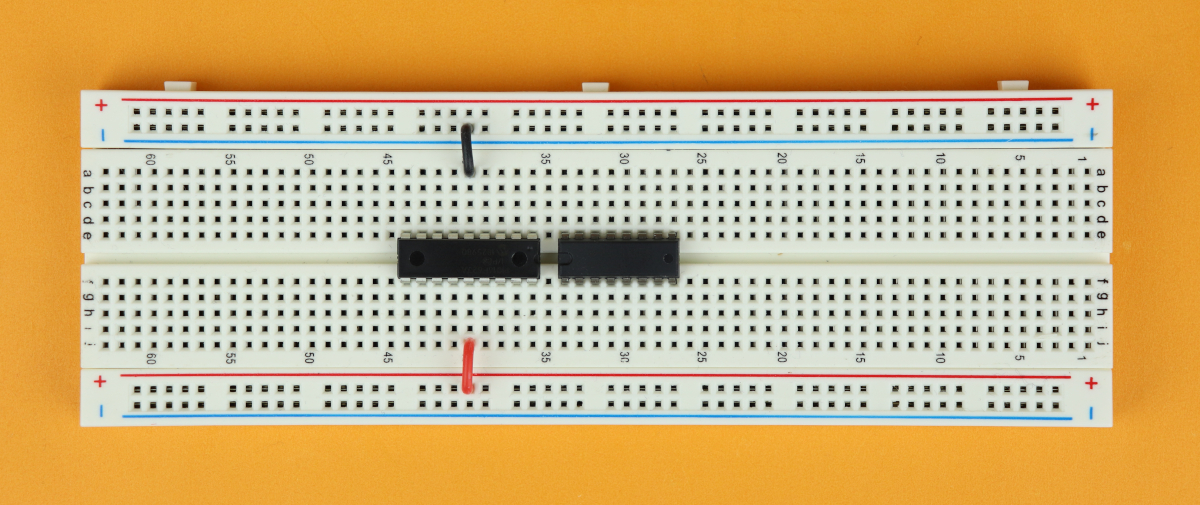
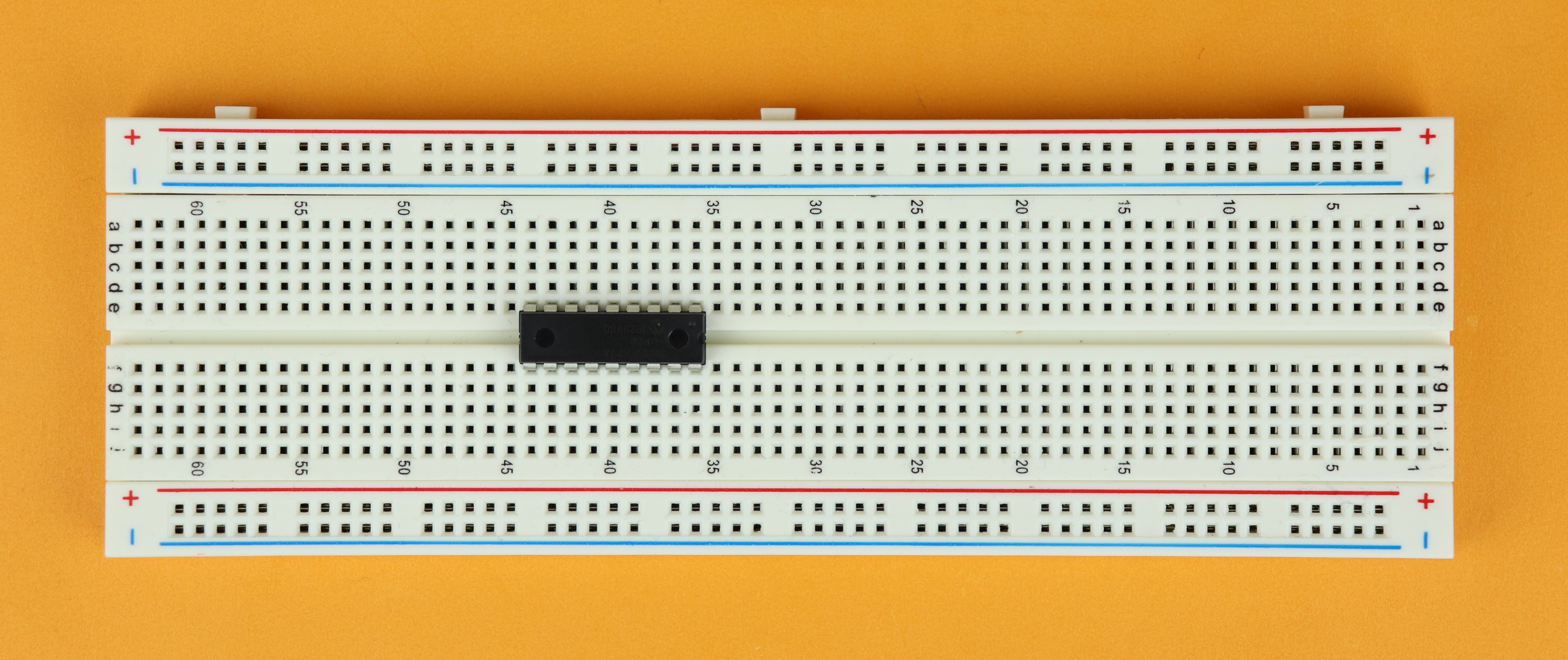
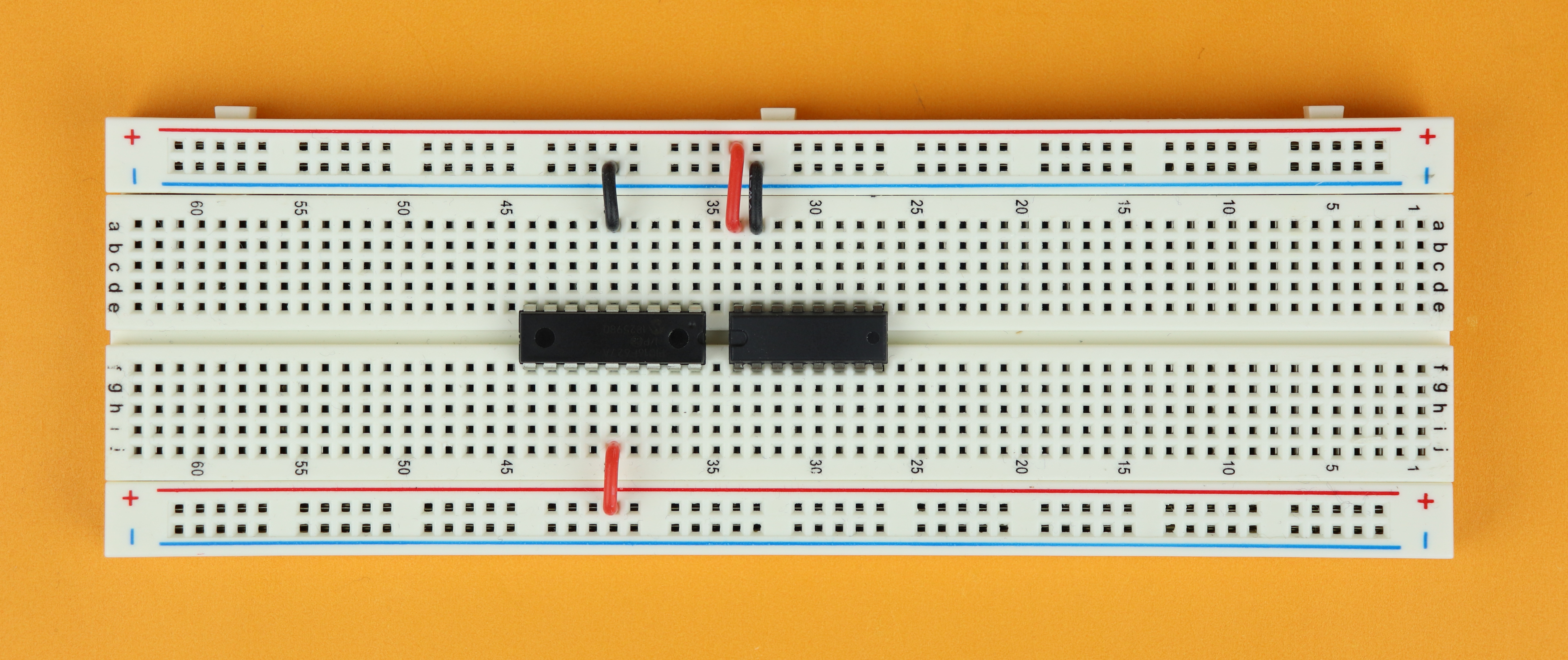
Step 2
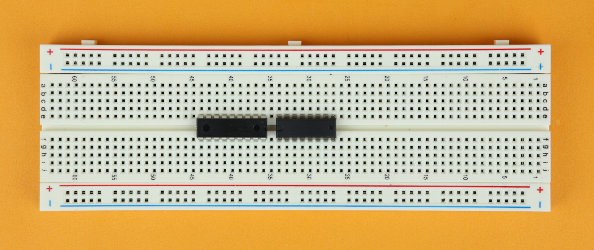
Insert the PIC16F627A in row 36 and make sure the notch points to the right. It's a bit hard to see in the picture, so click on it and zoom in. There are two circles on the PIC16F627A, but those are just leftovers from the injection molding process when the chip was made. The notch is located on the far right of the chip's housing, and it looks like a half circle.
-
-
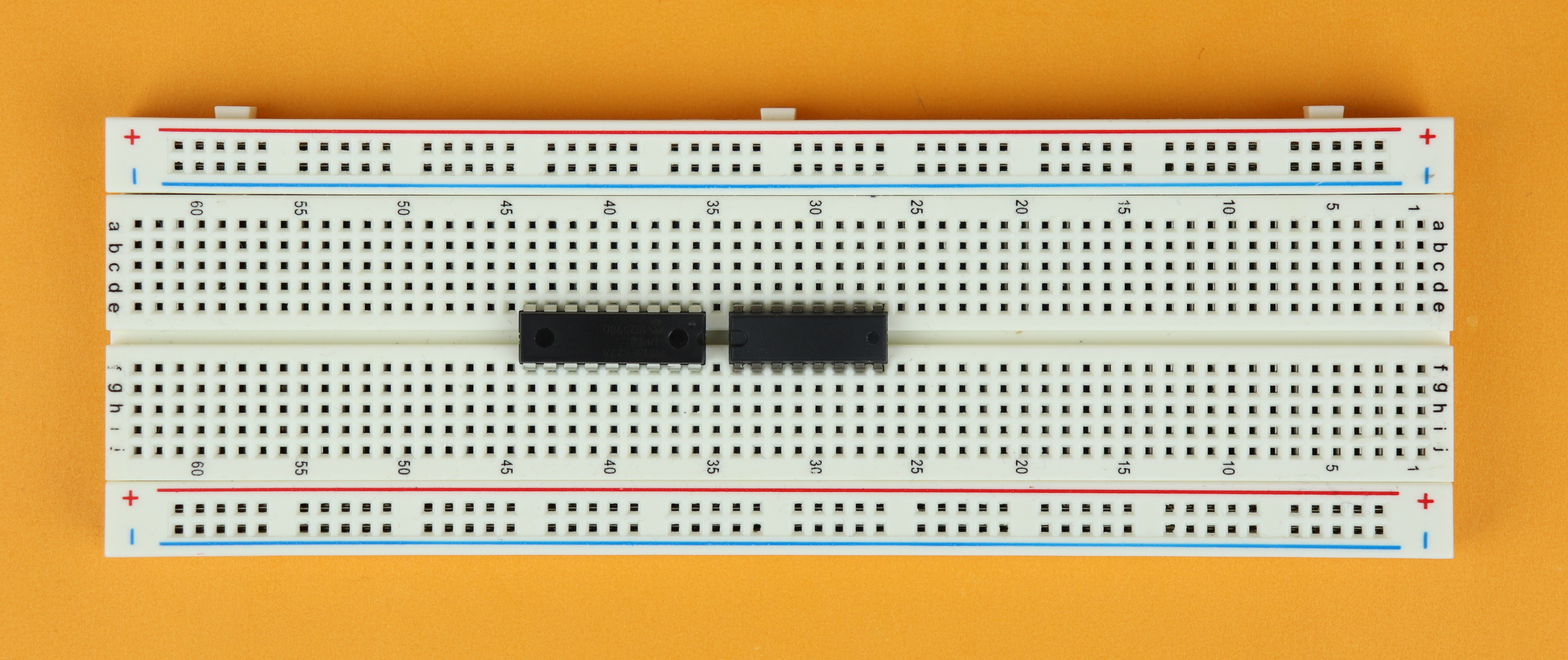
Step 3
Insert the MAX232 in row 27 and make sure the notch points to the left, just like in the picture. The notch is the half circle-type shape on the left. The round circle seen on the right is again just a leftover from the manufacturing process of the chip and has no meaning.
-
-
Step 4
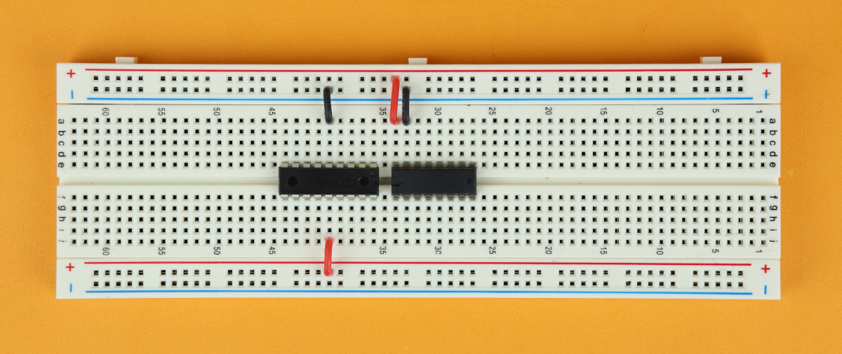
Connect the PIC16F627A's power terminals. Pin 5 goes to the ground rail (black/blue), and pin 14 goes to the VDD rail (red).
-
-
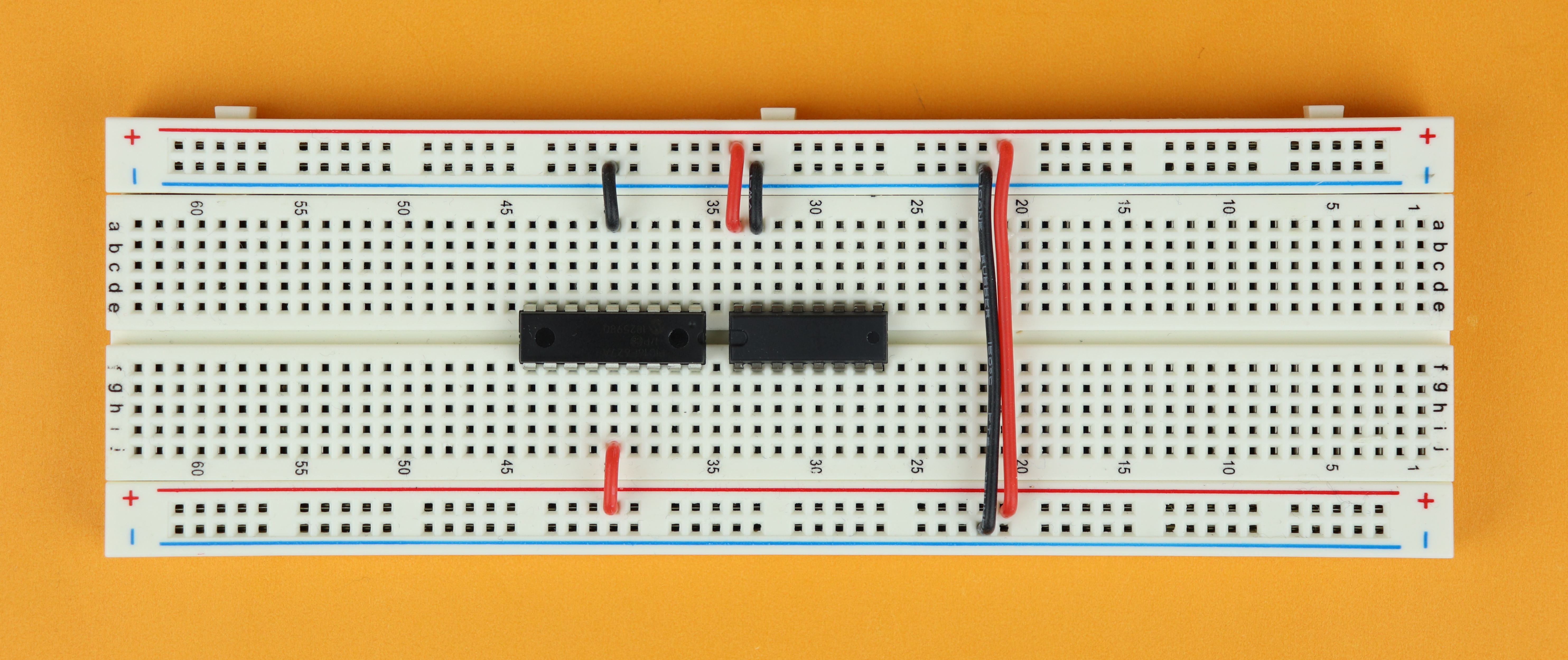
Step 5
Connect the MAX232's power terminals. Pin 16 is VDD (red), and pin 15 is ground (blue/black).
-

-
Step 6
Connect the power rails on either side of the breadboard. This is always convenient. Make sure you connect + with + and - with -, because otherwise there will be a short circuit.
-
-
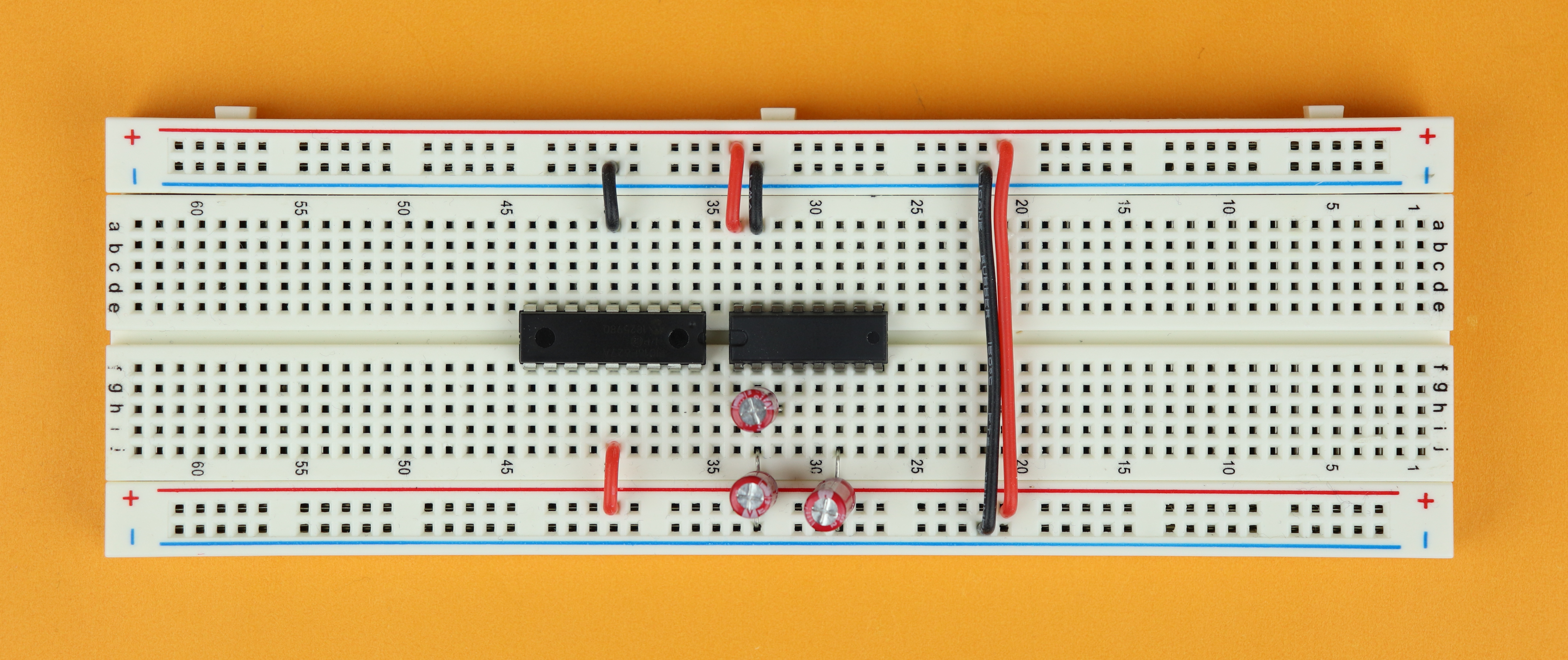
Step 7
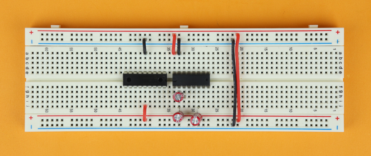
Place the three capacitors C1–C3. They are all 1μF values, so there is no risk of mixing them up.
Very important: Make sure you get the polarity right. Electrolytic capacitors have a positive and a negative terminal, and for most types the negative terminal has a large minus sign printed onto the housing. The negative terminal of C1 is connected to the ground rail. The negative terminal of C2 is connected to pin 6 of the MAX232. And the negative terminal of C3 is connected to pin 3 of the MAX232.
-
-
Step 8
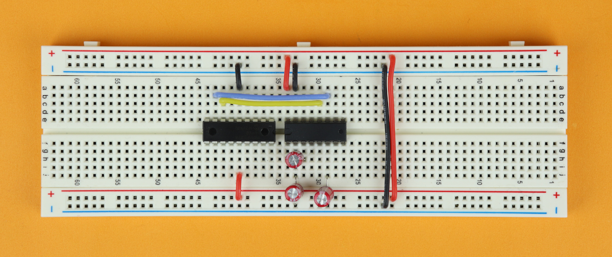
Connect the TXD pin of the MAX232 (pin 11) with the TXD pin of the PIC16F627A (pin 8), and connect the RXD pin of the MAX232 (pin 12) with the RXD pin of the PIC16F627A (pin 7).
-
-
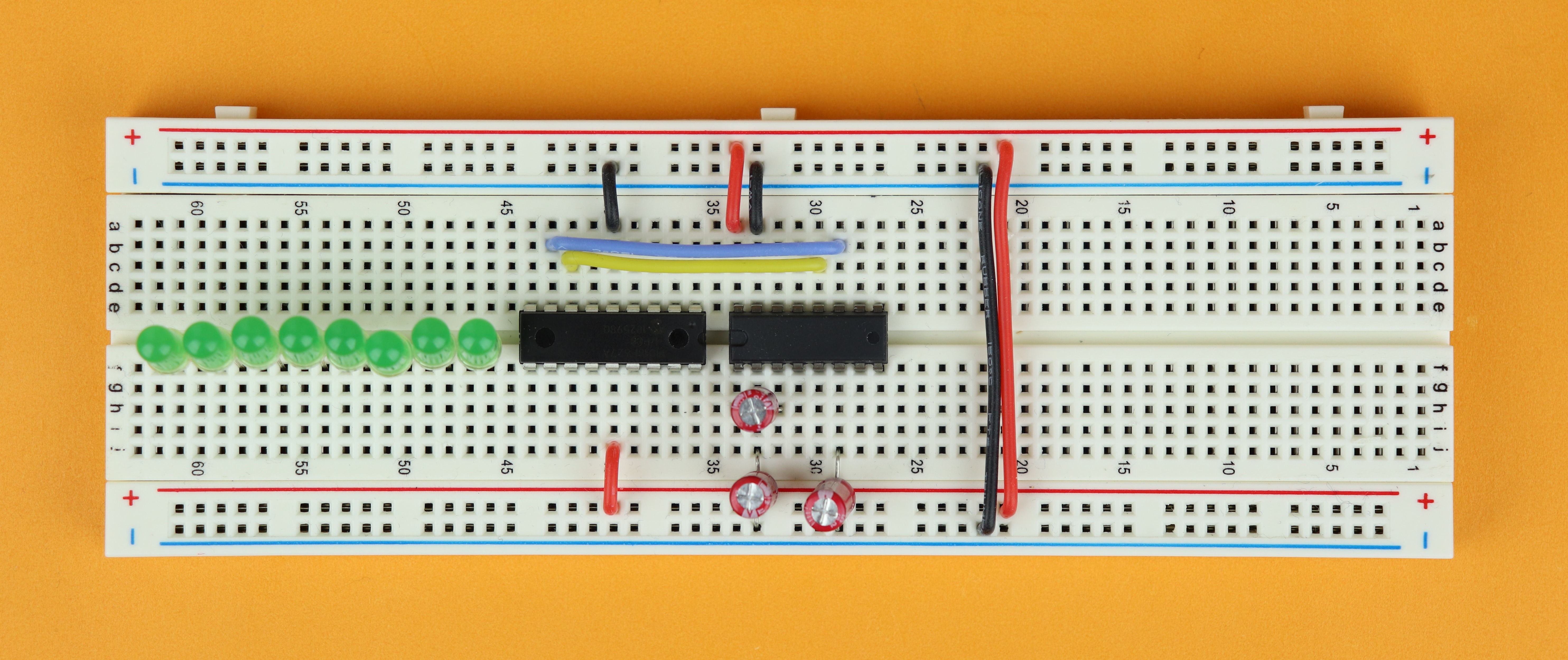
Step 9
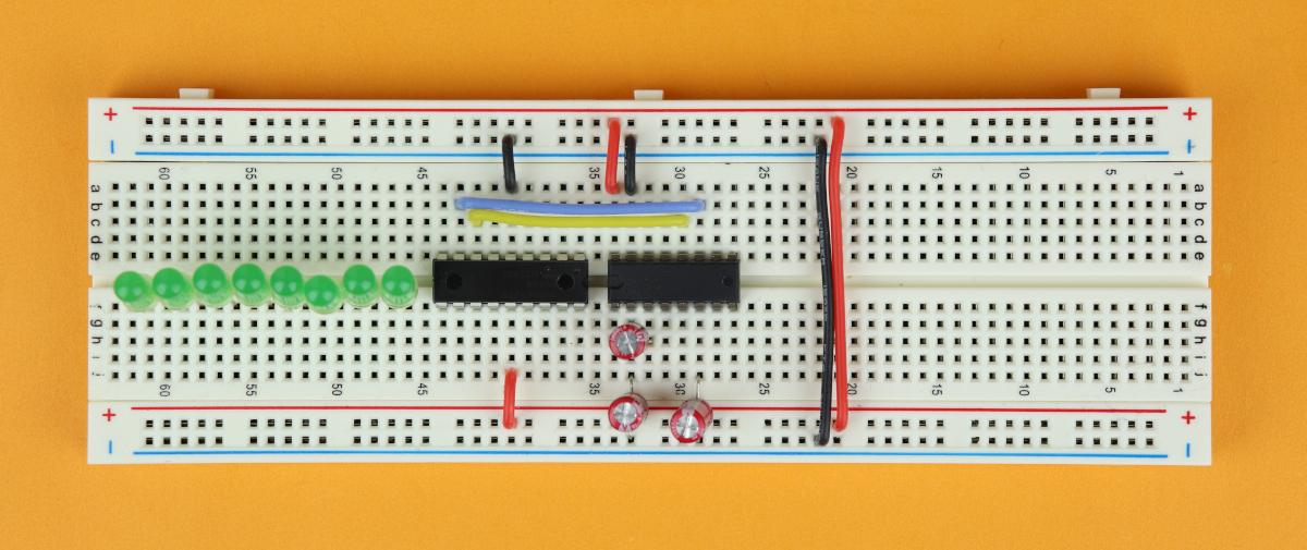
Place eight LEDs starting in row 46. Make sure that their anodes (the long wire, and their positive terminal) point to the right, and their cathodes (the short wire, and their negative terminal) points to the left.
In the picture above the perspective is a bit misleading, so here is a complete list: the anodes are connected to rows 46,48,50,52,54,56,58,60, and the cathodes are connected to rows 47,49,51,53,55,57,59,61. if you have placed the LEDs like in the picture above, there will be two free lines at the left of the breadboard.
-
-
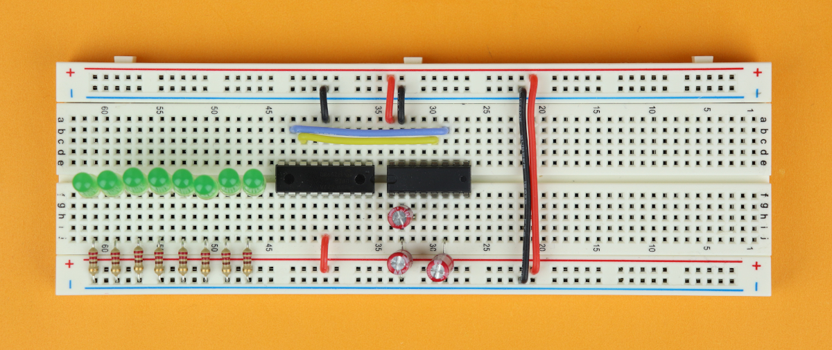
Step 10
Connect each LED cathode (see the previous step 9 for their precise locations) with a 220Ω resistor to the ground rail. Resistors can be plugged in either way, but if you look at the picture you can see that I arranged them with the gold ring all lined up. I did this because I think it looks nice, but you can plug them in either way, it's fine.
-
-
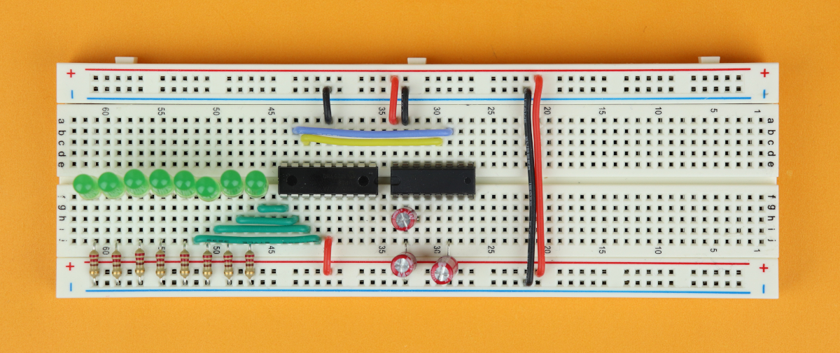
Step 11
Now it is time to connect the LED anodes. LED1 goes to pin 10, LED2 to pin 11, LED3 to pin 12, and LED4 to pin 13.
-
-
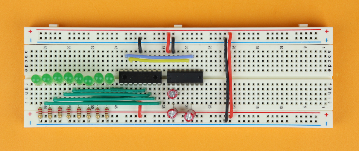
Step 12
LED5 goes to pin 15, LED6 goes to pin 16, LED7 goes to pin 17, and LED8 goes to pin 18. It is all very symmetrical.
-
-
Step 13
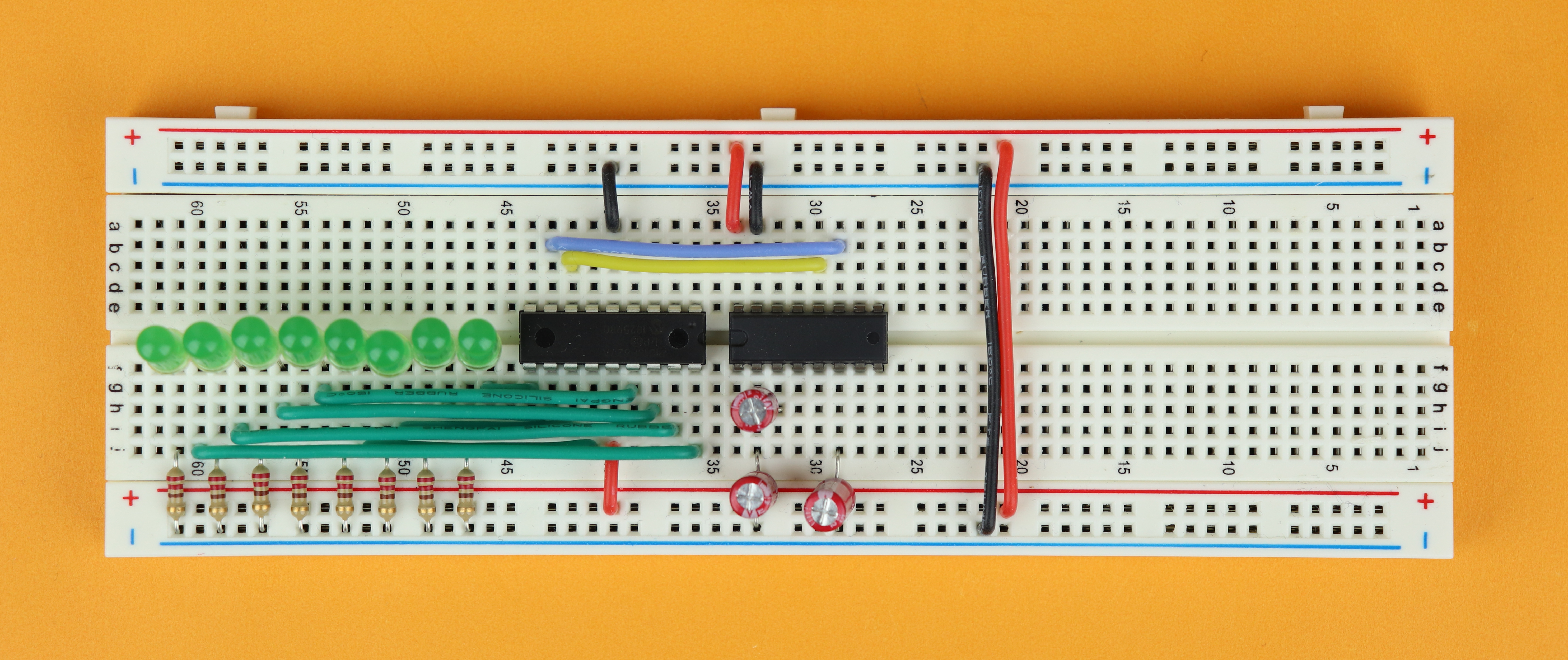
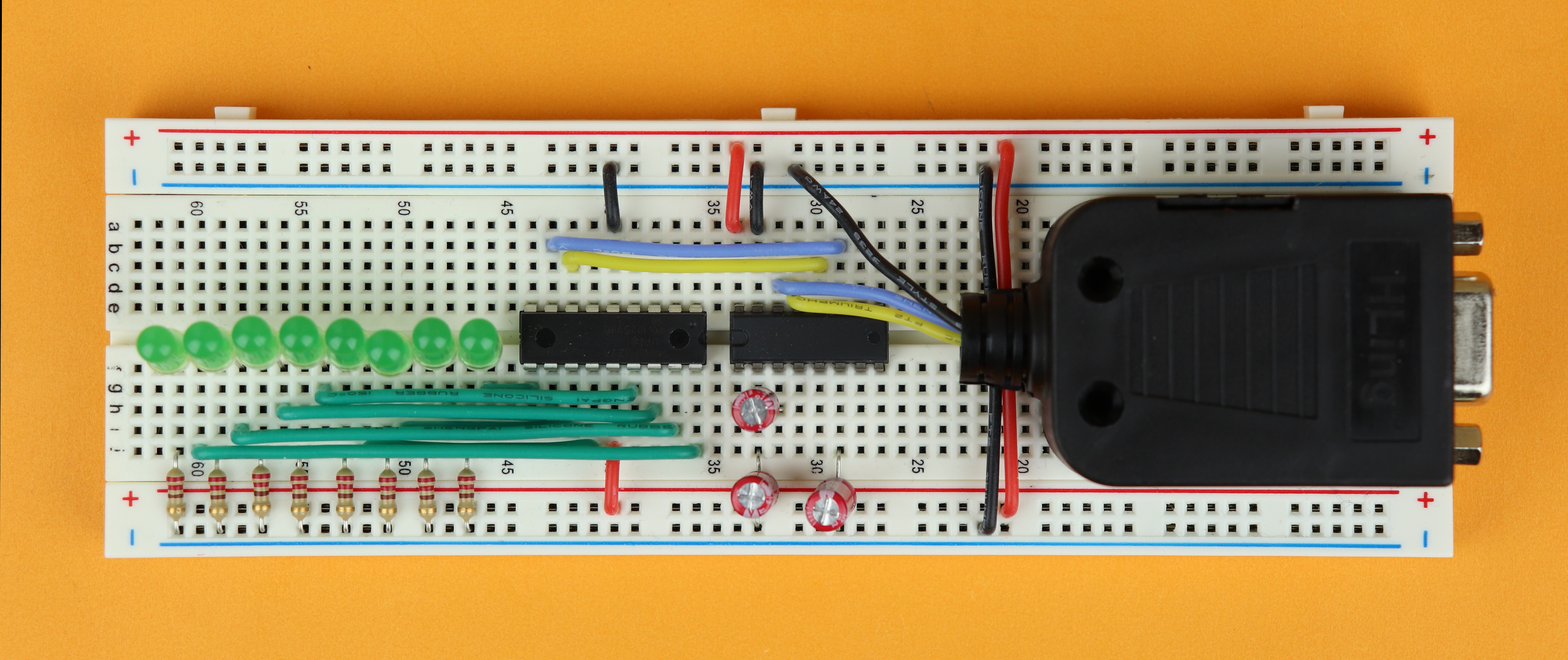
Now you can place the RS232 adapter on the breadboard. I used some double-sided tape to keep it in place. We need to connect three wires: TXD (blue), RXD (yellow), and GND (black). I have a separate photo below that shows how the wires are connected inside the adapter.
The TXD wire (blue) is connected to pin 14 of the MAX232, the RXD wire (yellow) is connected to pin 13 of the MAX232, and the ground wire (black) can be connected anywhere to the ground terminal.
-
-
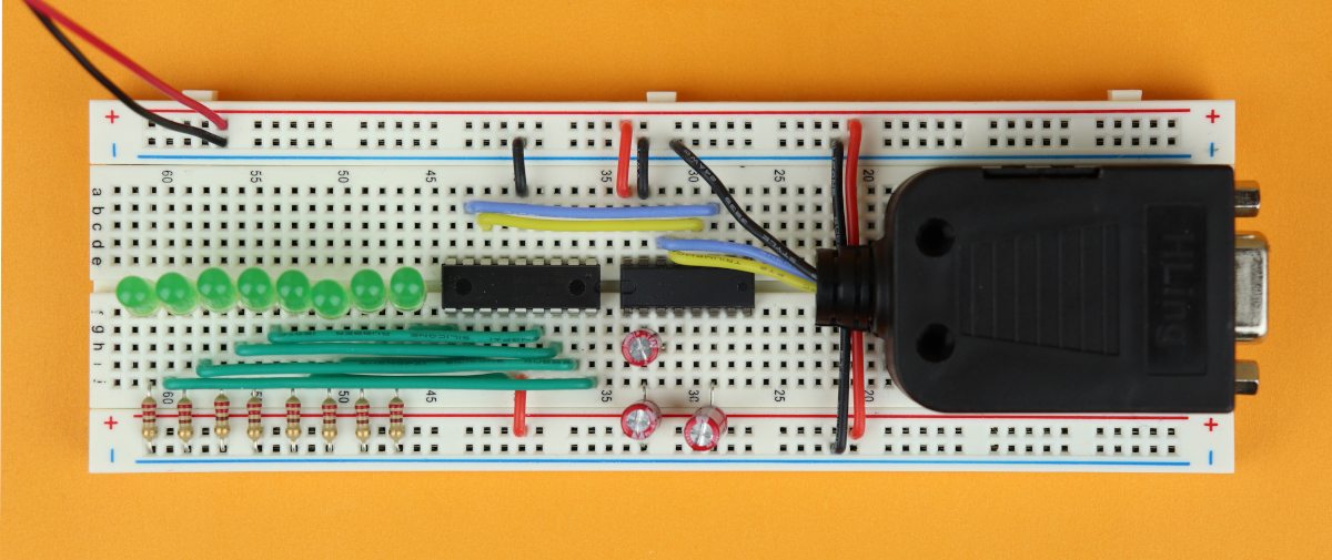
Step 14
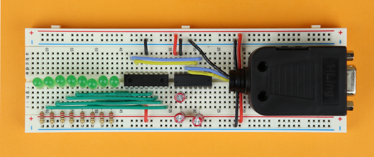
And now you can connect the 4.5V battery pack to the power rail. VDD goes to the positive (red) power rail, and ground goes to the negative (black) terminal. And you're all set!


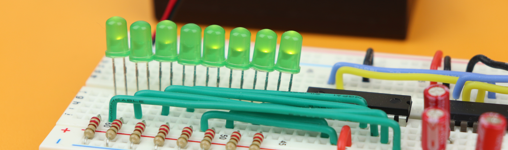
This is how the circuit looks like! And can you see which LEDs are on and off?
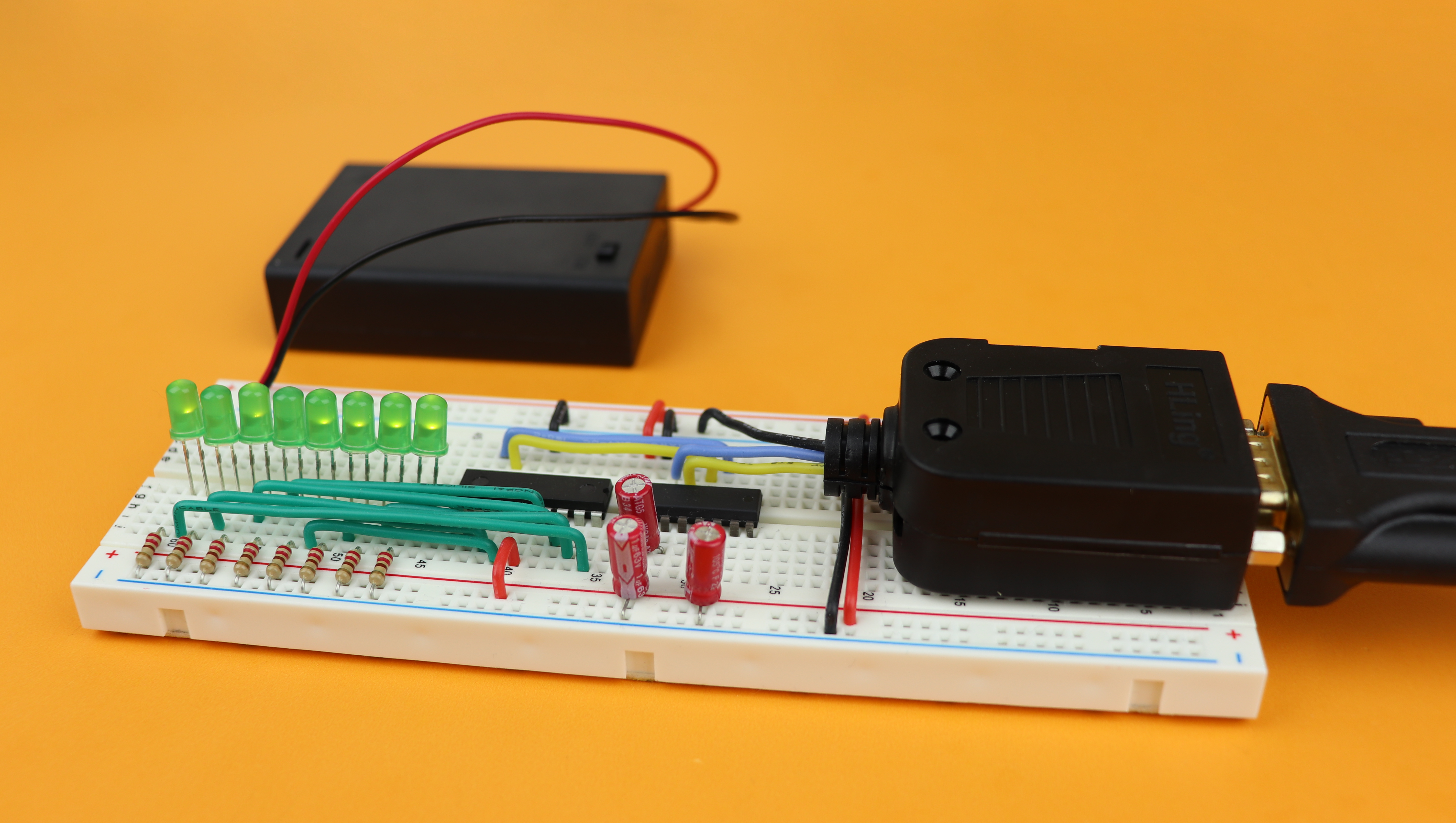
It's a bit hard to see, but LED1, LED2, LED3, LED4, LED6, and LED8 are turned ON, and LED5 and LED7 are off. This corresponds to the binary number 0b10101111, which in decimal is 175 :)
If you now open a terminal program, and send a number between 0 and 255, you can turn on and off any LED that you want! Isn't that cool?
Beyond RS232: RS422 for larger distances

Before wrapping up I wanted to mention one last thing: we haven't really talked about how long the RS232 cable can be before data is being lost. The answer is: not very! Already a few meters can lead to substantial data loss. Why is that? RS232, as a protocol, is not tailored for large distances, but rather for tabletop connections between several devices.
The reason for this loss of signal integrity is simple: RS232 only uses three wires. Two signal wires and one ground wire. This means that after a surprisingly short distance, the voltages can drop simply due to the internal resistance of the wires, which consecutively leads to undefined signal levels and data loss.
If you want to use the USART module to send and receive data over potentially a hundred or a thousand (!) meters worth of cable, RS232 is not a good idea. Rather, you should use a different protocol, for example the RS422 protocol. This protocol uses four wires instead of three: both the RX and the TX signal are defined as differential signals which significantly improves the signal robustness.
I don't want to go into a ton of detail about RS422 in this already somewhat lengthy article, but let me mention one important thing: you can still use the USART module! Okay, but then what's the difference? You just need a different level shifter IC. In this case, this level shifter IC is called MAX488. Just as before it has two
Here you can see the main idea of the MAX488 level shifter IC:
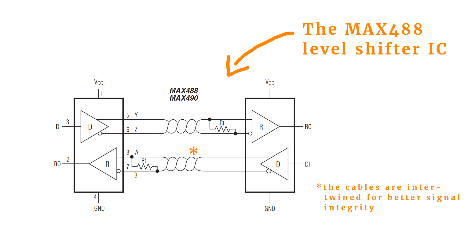
Under resources you can download the datasheet for the MAX488. You can also see that both pairs of cables are intertwined for improved signal integrity. Also, there is a resistor called Rt at the receiving channel, a typical value is around 120Ω, to match the impedance. Tuning this value depends on the cable that you use for the connection as well as the cable length.
YouTube video
I covered this entire tutorial in a dedicated YouTube video:
Final thoughts
Oof! That was a lot of information, I know. I still hope that I could convince you that using the RS232 interface can be very rewarding. To put it in a nutshell:
- Using RS232 is great because you can understand every single detail about it!
Even though we make use of the USART module, which is a bit of a black box, we can still understand all the steps involved. For USB this is a lot more complicated. There is nothing wrong with USB, of course, but it is a bit overkill for a beginner who is just learning how to use microcontrollers.
I am sure there are some details in this article that deserve some more explanation, and if you made it this far and found a piece that dows not make sense: please get in touch and let me know and I will do my best to improve this article! Thanks for reading :)
Appendix: the complete source code
/*
 * File:   main.c
 * Author: boos
 *
 * Created on March 28, 2020, 10:13 PM
 */

// CONFIG
#pragma config FOSC = INTOSCIO  // Oscillator Selection bits (INTOSC oscillator: I/O function on RA6/OSC2/CLKOUT pin, I/O function on RA7/OSC1/CLKIN)
#pragma config WDTE = OFF       // Watchdog Timer Enable bit (WDT disabled)
#pragma config PWRTE = OFF      // Power-up Timer Enable bit (PWRT disabled)
#pragma config MCLRE = OFF      // RA5/MCLR/VPP Pin Function Select bit (RA5/MCLR/VPP pin function is digital input, MCLR internally tied to VDD)
#pragma config BOREN = OFF      // Brown-out Detect Enable bit (BOD disabled)
#pragma config LVP = OFF        // Low-Voltage Programming Enable bit (RB4/PGM pin has digital I/O function, HV on MCLR must be used for programming)
#pragma config CPD = OFF        // Data EE Memory Code Protection bit (Data memory code protection off)
#pragma config CP = OFF         // Flash Program Memory Code Protection bit (Code protection off)

#include <xc.h>

// global variable that stores the received 8-bit value
unsigned char value = 0;

// define LED locations for later convenience
#define LED1 RB4
#define LED2 RB5
#define LED3 RB6
#define LED4 RB7
#define LED5 RA6
#define LED6 RA7
#define LED7 RA0
#define LED8 RA1

// main function
void main (void) {

	// set tristate registers

    // tristate bits for RB1 (RX) and RB2 (TX)
    // must both be set to 1 in USART mode
    TRISB1 = 1;
	TRISB2 = 1;

    // LEDs are outputs
    TRISB4 = 0;
    TRISB5 = 0;
    TRISB6 = 0;
    TRISB7 = 0;
    TRISA0 = 0;
    TRISA1 = 0;
    TRISA6 = 0;
    TRISA7 = 0;

    // disable analog features on PORTA
    // (we don't need them here)
    CMCON = 0b111;

	// configure USART module

	// slow Baud rate
	BRGH = 0;

	// set Baud rate to 1200
	// f_osc = 4MHz
    // SBPRG = fosc/(64 x Baud rate) - 1
	SPBRG = 51;

	// set to asynchronous
	SYNC = 0;

	// enable serial port
	SPEN = 1;

	// enable interrupts for receiving data
	RCIE = 1;

	// enable receiving module
	CREN = 1;

	// interrupts

    // global interrupts enabled
	GIE = 1;

    // peripheral interrupts enabled
	PEIE = 1;

	// main loop
	while (1) {

        // update LEDs
        LED1 = value & 1;
        LED2 = (value >> 1) & 1;
        LED3 = (value >> 2) & 1;
        LED4 = (value >> 3) & 1;
        LED5 = (value >> 4) & 1;
        LED6 = (value >> 5) & 1;
        LED7 = (value >> 6) & 1;
        LED8 = (value >> 7) & 1;

	}

    return;

}

// interrupt service routine
void __interrupt () isr (void) {

  // received some data via USART?
  if (RCIF) {

    // retrieve value
    value = RCREG;

    // send value back
	TXREG = value;
	TXEN = 1;

    // react to possible errors (we skip that here)
    CREN = 0;
    CREN = 1;
    OERR = 0;
    FERR = 0;

  }

}


