Making a safe with servos & NE555 timers
August 27, 2022 • project
If you are searching for a fun, beginner-friendly electronics project: look no further. Today we will build a simple safe using basic components such as servo motors and NE555 timer chips. We will go through all steps in great detail, and in the end you will have your very own safe. Let's go!

Don't forget that there is a YouTube video for this entire project, if you prefer to watch a video. Usually the article and the video give about the same information, but in this case the video may be slightly more informative when it comes to the mechanical aspects of the build.
Main idea
So the main idea is very simple: servos have a range of 180 degrees, and we can control that with a simple potentiometer and an NE555 timer, more on that later. And if we arrange these servos the right way we can turn them into a lock. Only if all three servos are turned exactly to the right position the door will open, otherwise it will remain locked.
And if you want to set a new code, first open the door. Then, detach the three servo arms from the servos, which can be a bit fiddly. Set the knobs to your new combination. And last, reattach the servo arms, and you have just set a new code. How easy is that, all without a microcontroller.
What you need
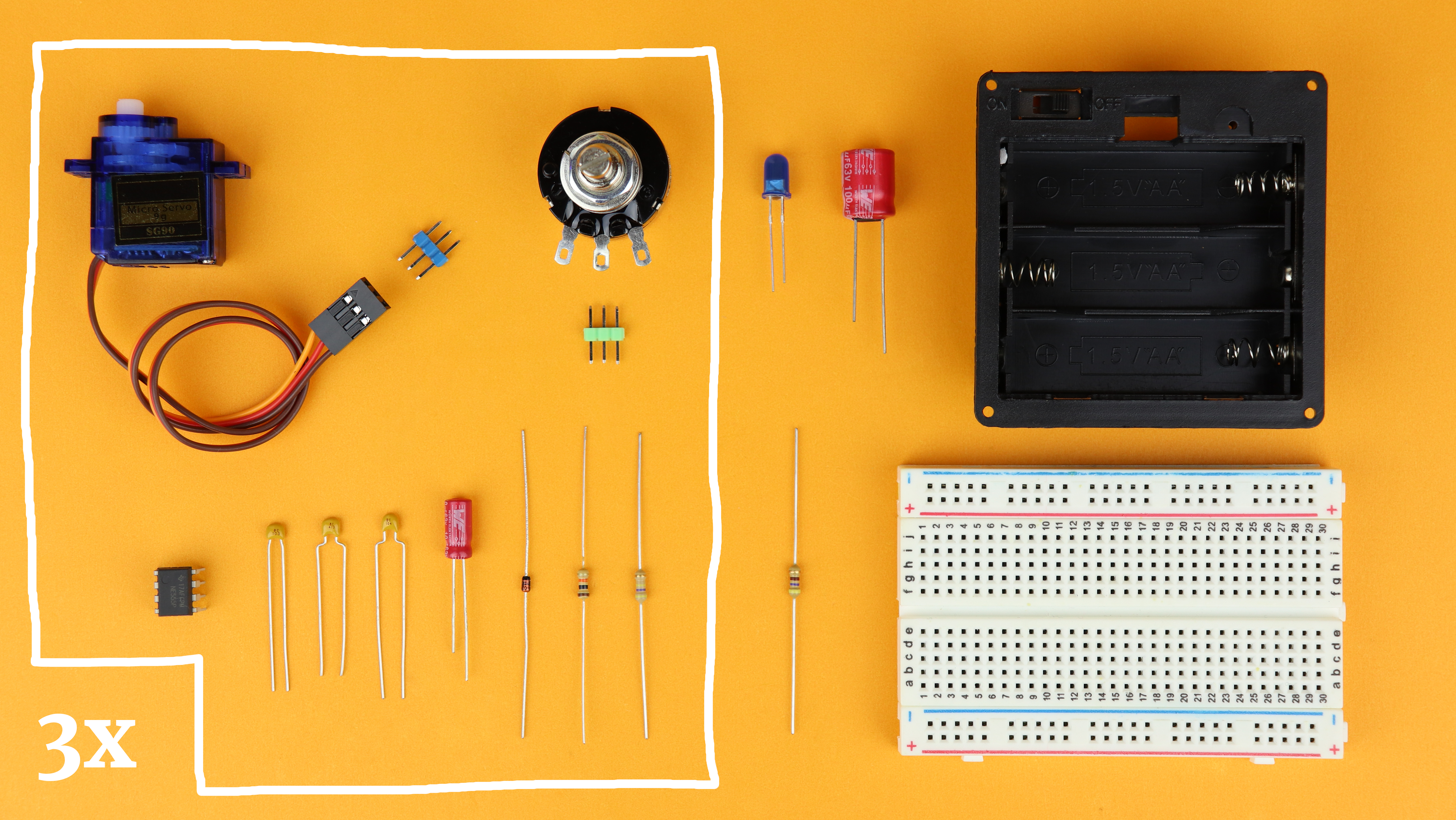
Here you can see all the components needed for this build. Well, the stuff in the box you actually need 3× (or more/less, depending om how many servos you want to control). There are links on where to buy all of these parts in the components box.
The main idea is to use the NE555 timer IC to drive the servo motors. Check out our previous tutorial on the NE555 to learn more about it. The NE555 is connected to a potentiometer, and with this potentiometer we can adjust the pulse width of the signal that the NE555 creates. And the remaining parts are just resistors and capacitors that set the speed and pulse widths of the signal, and other capacitors are just here for stability, more on that below when we talk about the schematic.
How to control servos
But let's back up for a second. What are servos, and how do we control them?
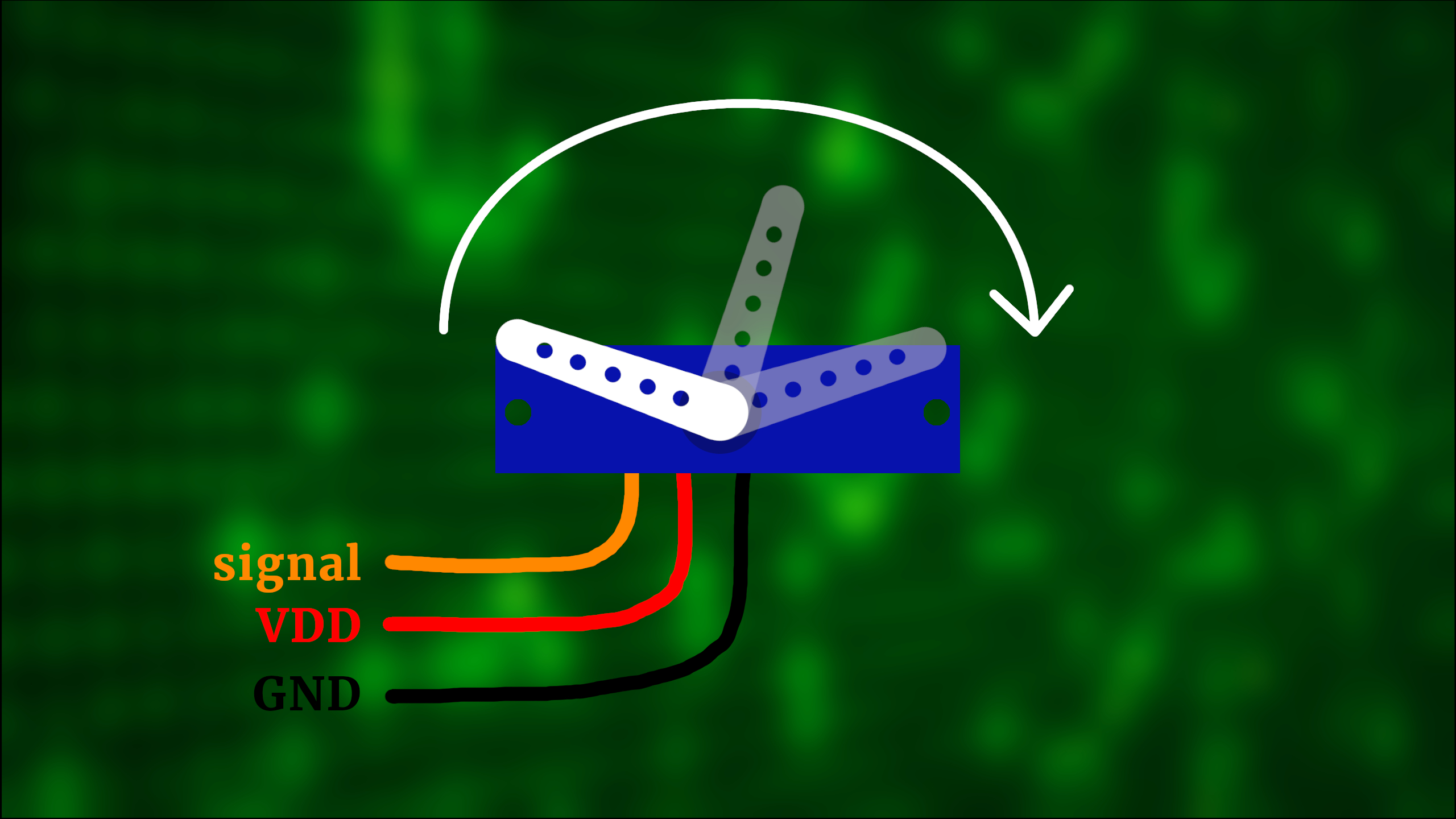
Servos are little mechanical devices that typically have one arm that can be rotated in a range of 180 degrees, and we can set this position electronically very accurately.
Servos have three pins: a signal pin, and to power supply pins (and they take a voltage of 4-5V, which makes them perfect for the use with batteries). The signal pin expects a signal that is between 0.5ms to 2.5ms long, and depending on the length of that pulse it sets the position of its little arm.
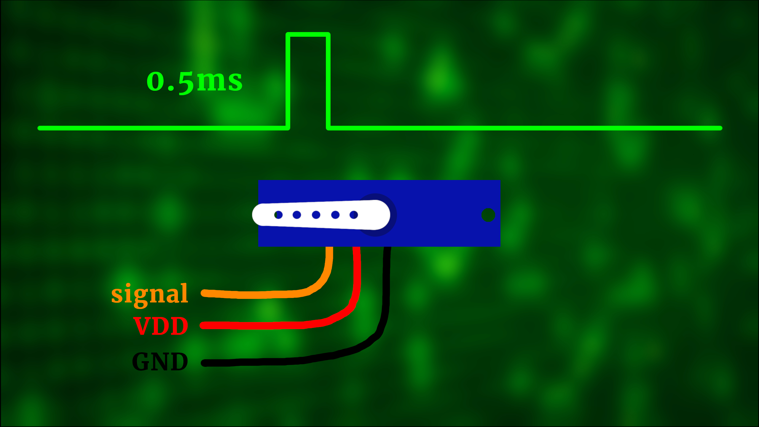
Sound complicated? Not really! A 0.5ms pulse, for example, makes the arm turn all the way to the left:
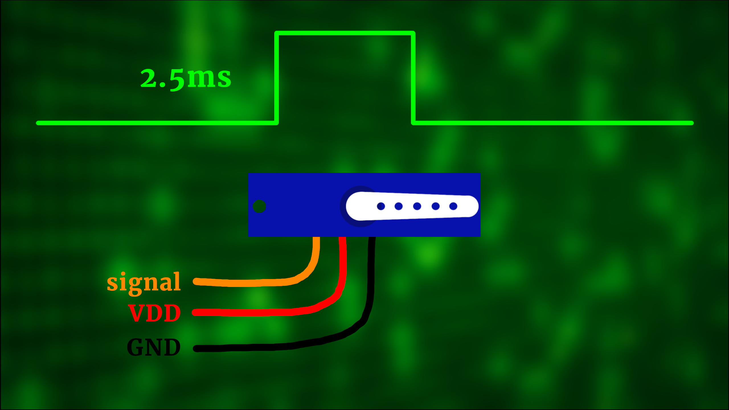
And a 2.5ms pulse, on the other hand, makes it turn all the way to the other end to the right:
And if the signal duration is in between, then the arm will be in between as well:
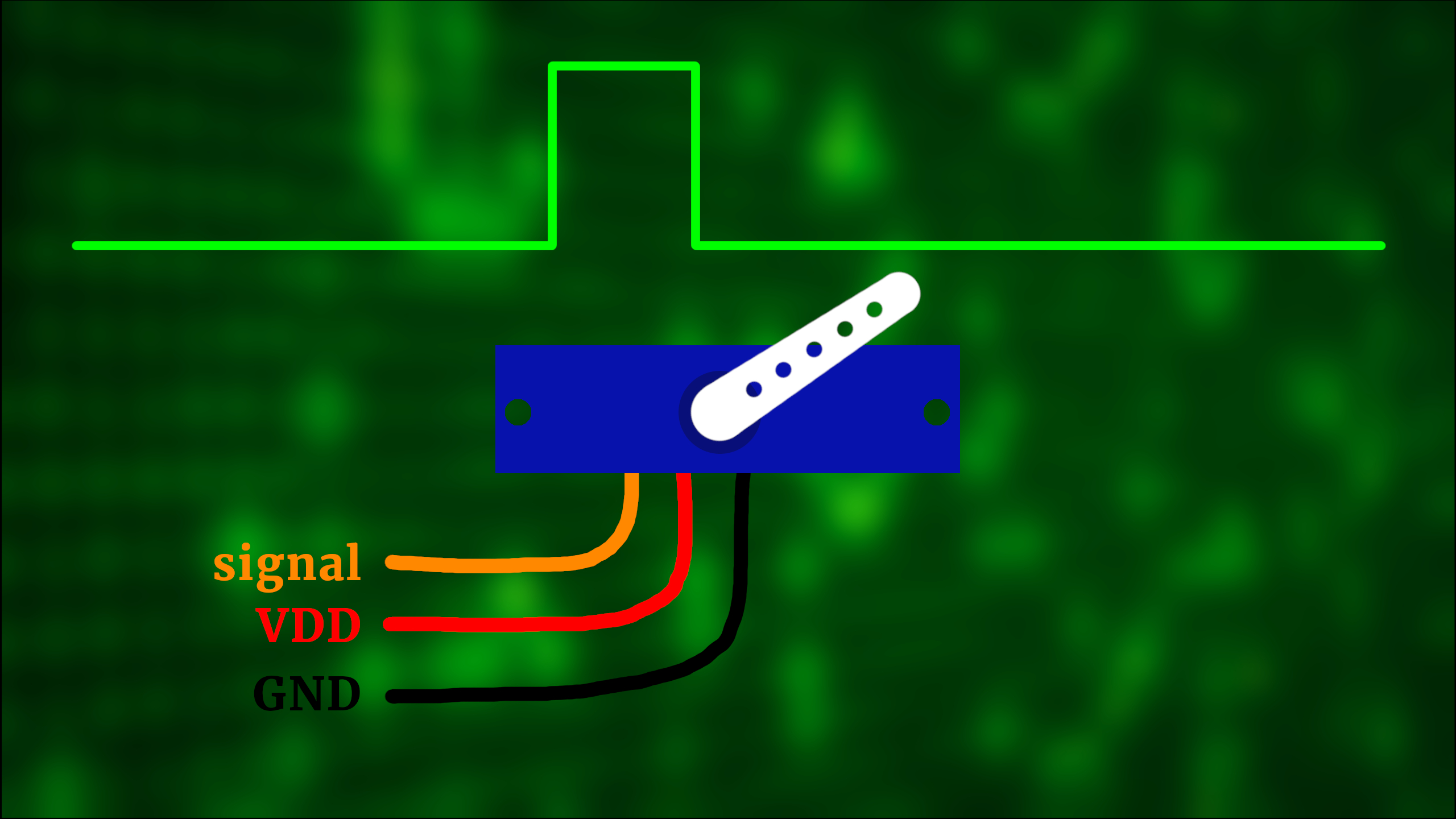
The refresh rate of these signals is around 50 times per second, but this is not really critical and can be slightly faster (or much slower).
Now for some servos these times are slightly different; for example, some servos only accept pulse widths from 1ms to 2ms. So it's a good idea to always check your servo's datasheet. We are using a small servo by the name of SG90 (datasheet), but I found out experimentally that the best timings do not agree completely with what is in the datasheet. For example, for our servo today the 0.5ms-2ms works best. The good news is that these times are easily adjustable, so: no worries, we will get into that later. And by later, I mean now!
Schematic
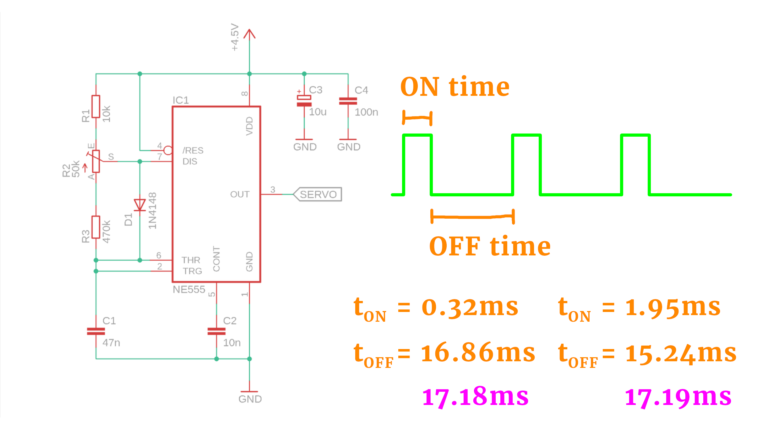
To control our servos, we have to create a signal that is ON for around 0.5ms-2.5ms. Here is the NE555 configured as an astable oscillator that does just that:
My apologies, there is a lot going on here, I know. But as always, let us break it down into little pieces. First of all, if you are new to the NE555 then I invite you to check out the NE555 tutorial first, where we talk about this exact schematic in a lot of detail :)
But maybe you are just interested in the main idea, then keep reading here!
- The ON-time is set by the 47nF timing capacitor C1 in the bottom left, and the resistor R1 and whatever part of R2 is on the upper side of the potentiometer's wiper. And, you guessed it, the OFF-time is set by R3 and the other side of R2.
- In the left column you can see the ON time for the potentiometer turned all the way up, and all the way down is the number on the right. Same for the OFF times. You see that these times are very close to the 0.5ms and 2ms that we need for our SG90 servo. if you want to know how to calculate these times, check out the NE555 tutorial :)
- If you wanted to have super exact timings, you could replace R1 by a 20kΩ potentiometer, and R3 by a 500kΩ potentiometer. But in most cases this is not needed, and I find that for this purpose the values above work great.
- Did you notice that the sum of ON time and OFF time is always the same (purple numbers)? That is thanks to the diode D1. It makes sure that the capacitor C1 is only ever charged through R1 and R2, and never through R3. This way, the overall period stays the same, no matter what the position of R2 is.
- Last, the capacitors C2, C3, and C4 are just there for stability. I actually built this circuit without C2 at first, and it would no work reliably. So, yes: these capacitors are your friends, don't forget about them :)
Okay, this is the schematic for one servo, but we are driving three of them today. So, after copying & pasting this circuit three times we have arrived at the final schematic:
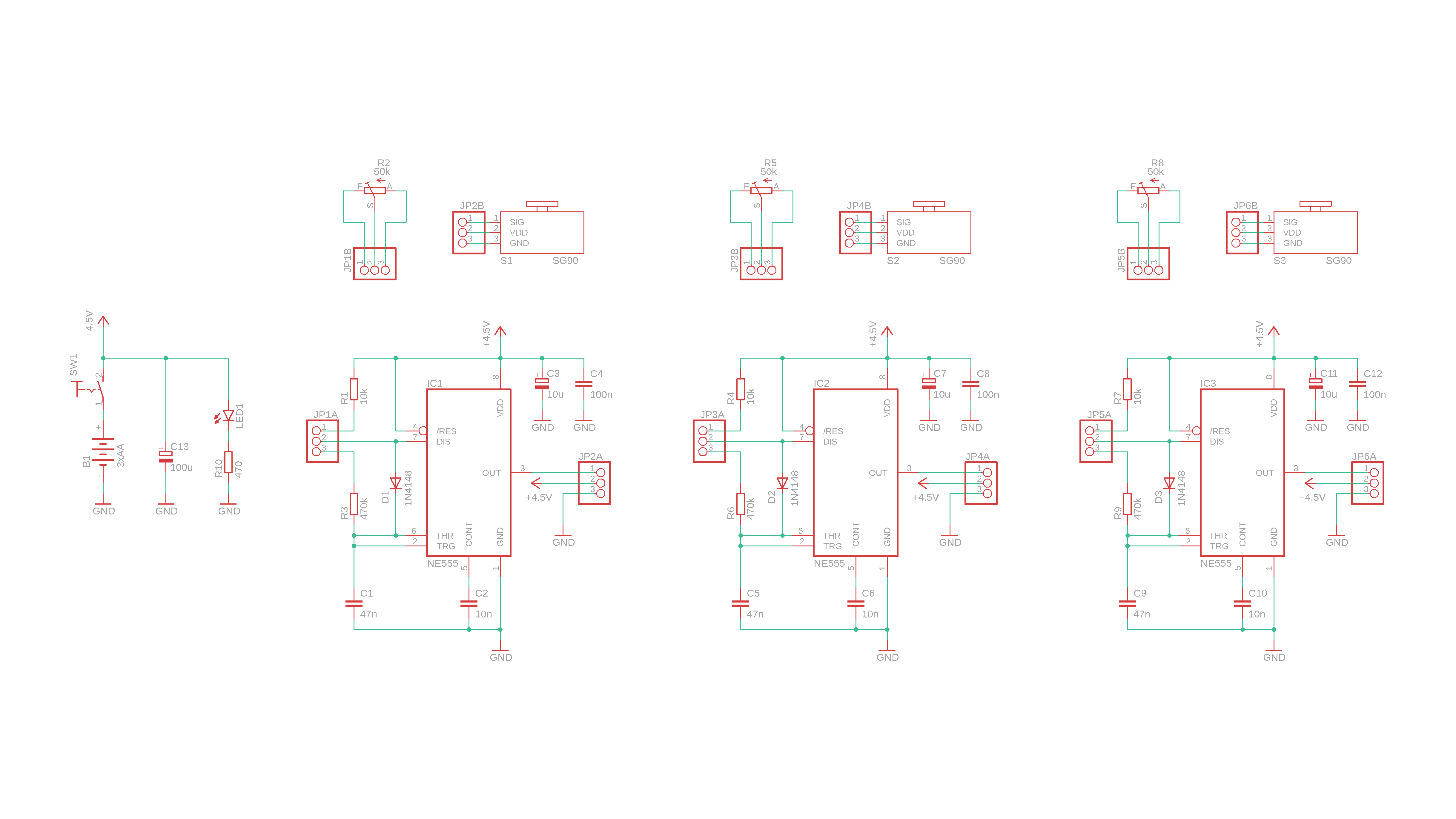
It looks a bit more complicated because I added some pinheaders to the schematic, and that is because we will connect the servos and the potentiometers with longer leads. The symbol on the very left is our 4.5V AA battery pack (with an included ON/OFF switch for convenience), the 100μF capacitor C13 is a bulk capacitor for stability, and LED1 is a status indicator (because otherwise there would be no way to tell if the circuit is ON or OFF, and if you want to save battery power this is one way to do it).
Building the circuit
And with that out of the way, let's build this circuit on a breadboard!
-
-
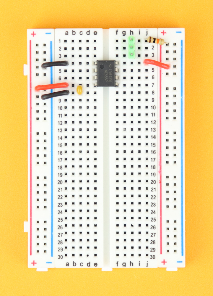
Step 1
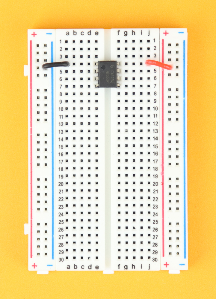
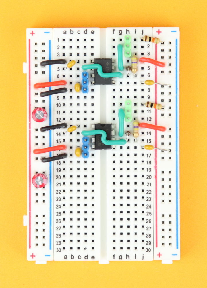
Place the 400-pin breadboard in front of you, with row 1 facing to the top :) Insert the NE555 in row 4, and connect it to VDD on pin 8, and to ground on pin 1.
-

-
Step 2
Next, connect the reset pin to VDD as well, and add the 100nF filter capacitor C4.
-
-
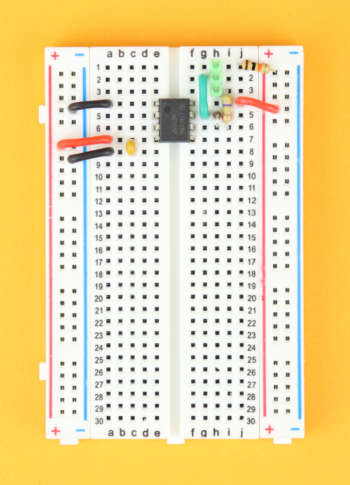
Step 3
Insert R1 between row 1 and the positive power rail and insert the potentiometer pinheader in row 1 on the top right.
-

-
Step 4
Connect the pinheader's center pin down to pin 7 of the NE555.
-
-
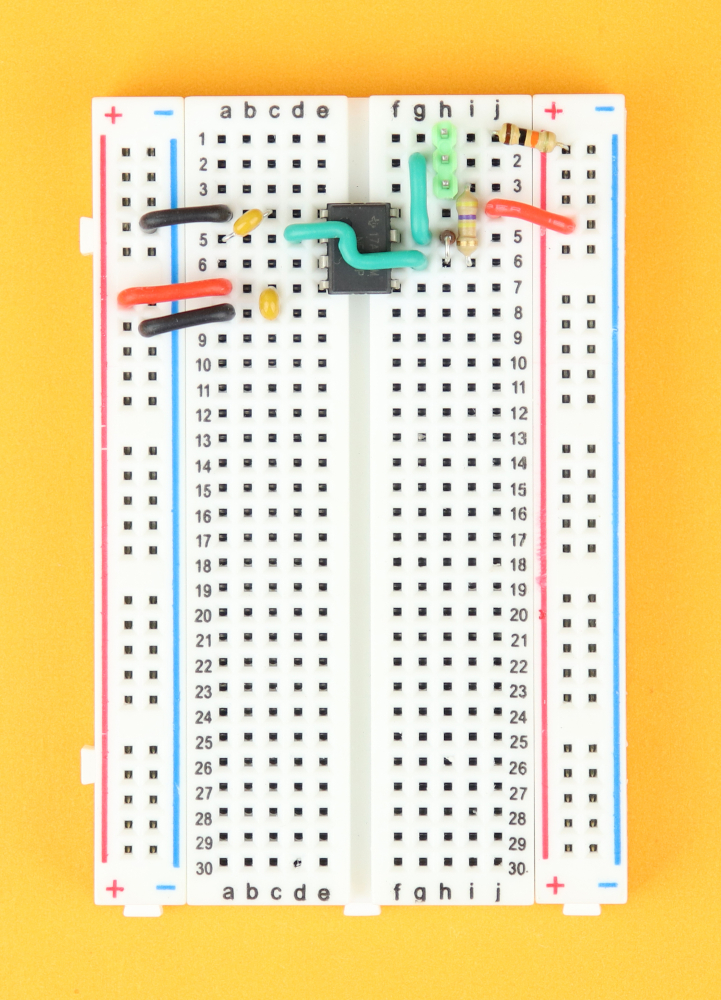
Step 5
Connect the pinheader's lower pin to pin 7 of the NE555 via the resistor R3, and insert the diode D1 between pins 6 and 7. Make sure that the diode's cathode, the side with the black ring, is connected to pin 6.
-

-
Step 6
Connect pins 6 and 2 of the NE555.
-
-
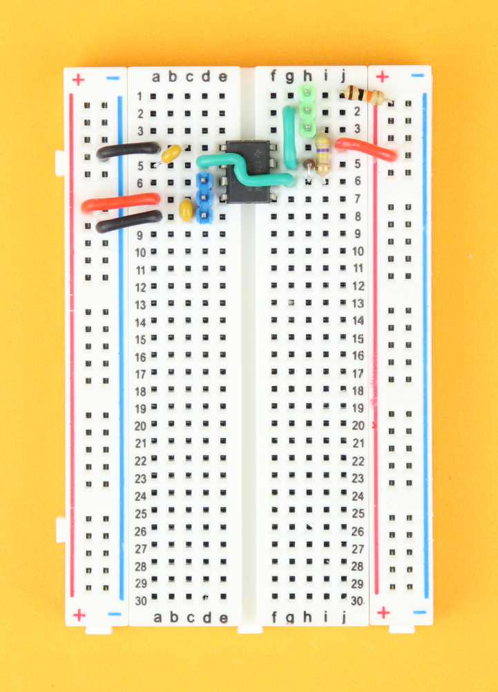
Step 7
Insert the timing capacitor C1 from pin 2 to ground.
-
-
Step 8
Place the servo pinheader in row 6.
-

-
Step 9
Insert C2 from pin 5 to ground, and insert the bulk capacitor C3 in the power rail close to the NE555.
-
-
Step 10
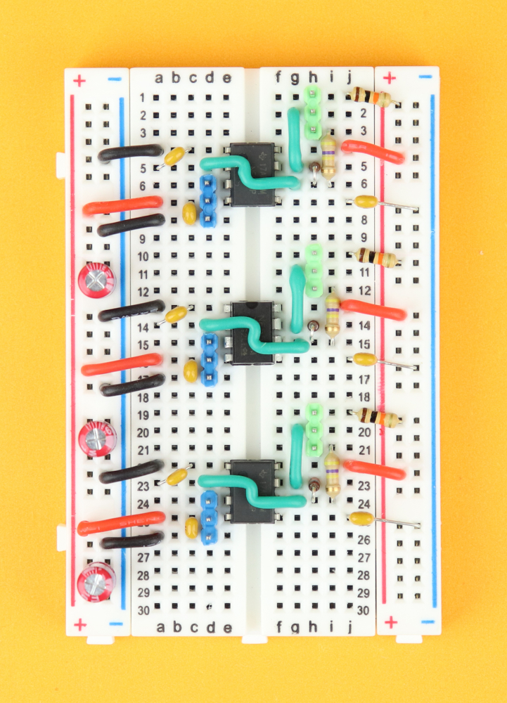
Copy & paste the circuit one time...
-
-
Step 11
...and another time :)
-
-
Step 12
Now connect the positive power rails on either side of the breadboard with wires in row 9.
-

-
Step 13
...and also connect the negative power rails on both sides, and for this one row 17 works well.
-

-
Step 14
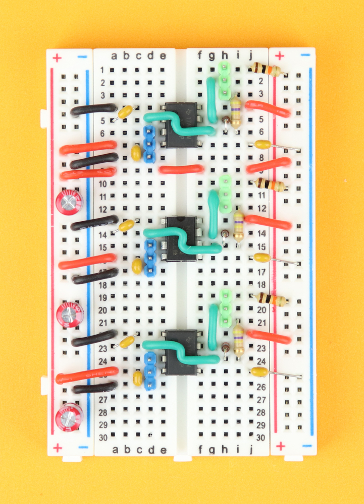
Place the chunky 100uF bulk capacitor in the power rail at the bottom right for extra stability.
-
-
Step 15
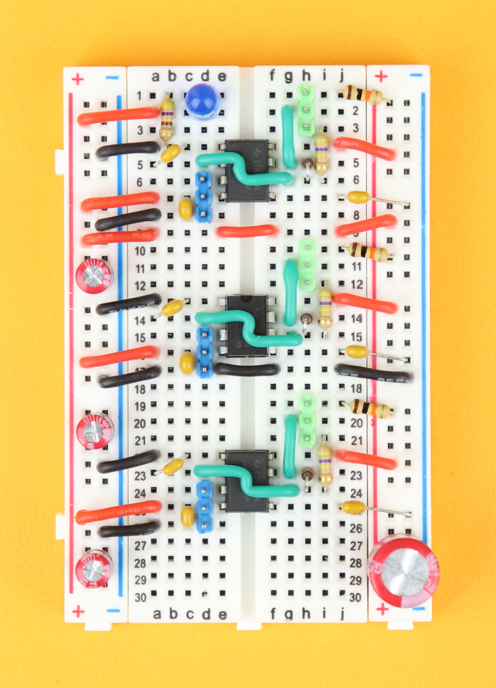
Connect a positive wire to row 2 on the top left, insert LED1 with its positive terminal in row 2, and connect its cathode to ground with R10.
-

-
Step 16
And now, when we connect power, LED1 will be our ON indicator LED.
And we're done with the breadboard! At this point, the pinheaders are just placeholders. Later in tis build I remove the pinheaders and permamently solder the potentiometer and servo wires to them, because it gives us a very secure fit:
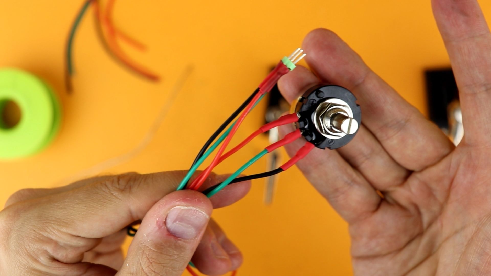
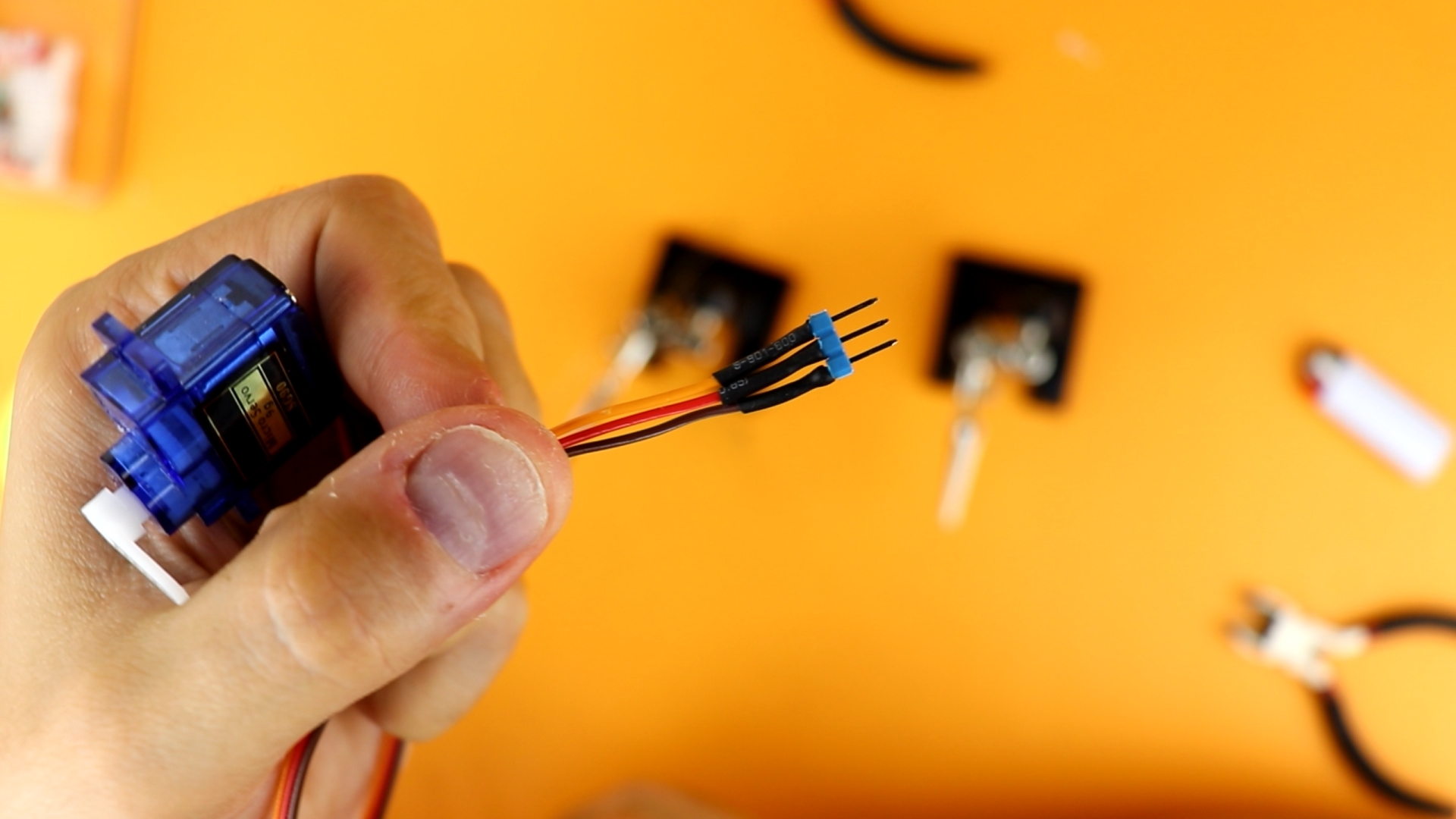
But if you do not want to solder you can also use Dupont-style wires, and I linked them in the components box.
Constructing the safe
So here is the empty box we want to turn into a safe:
![]()
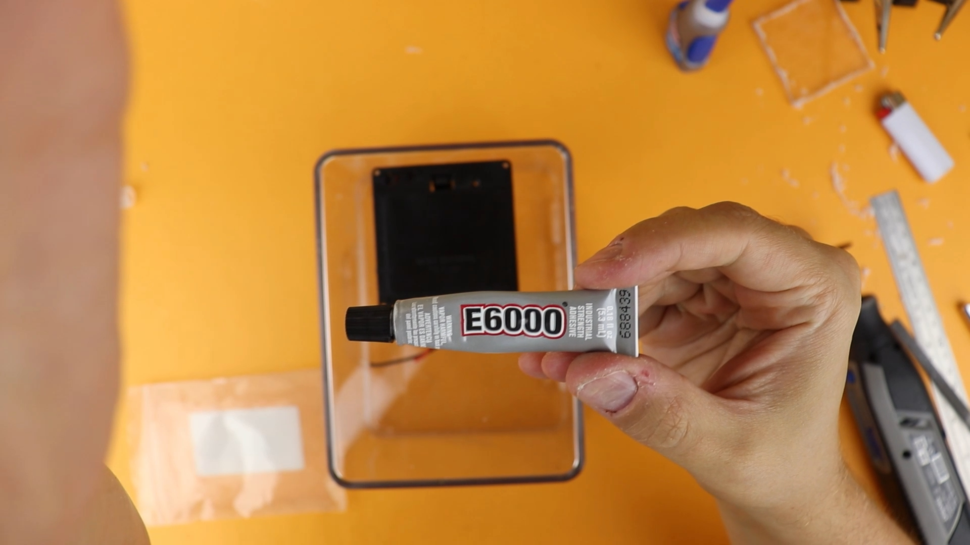
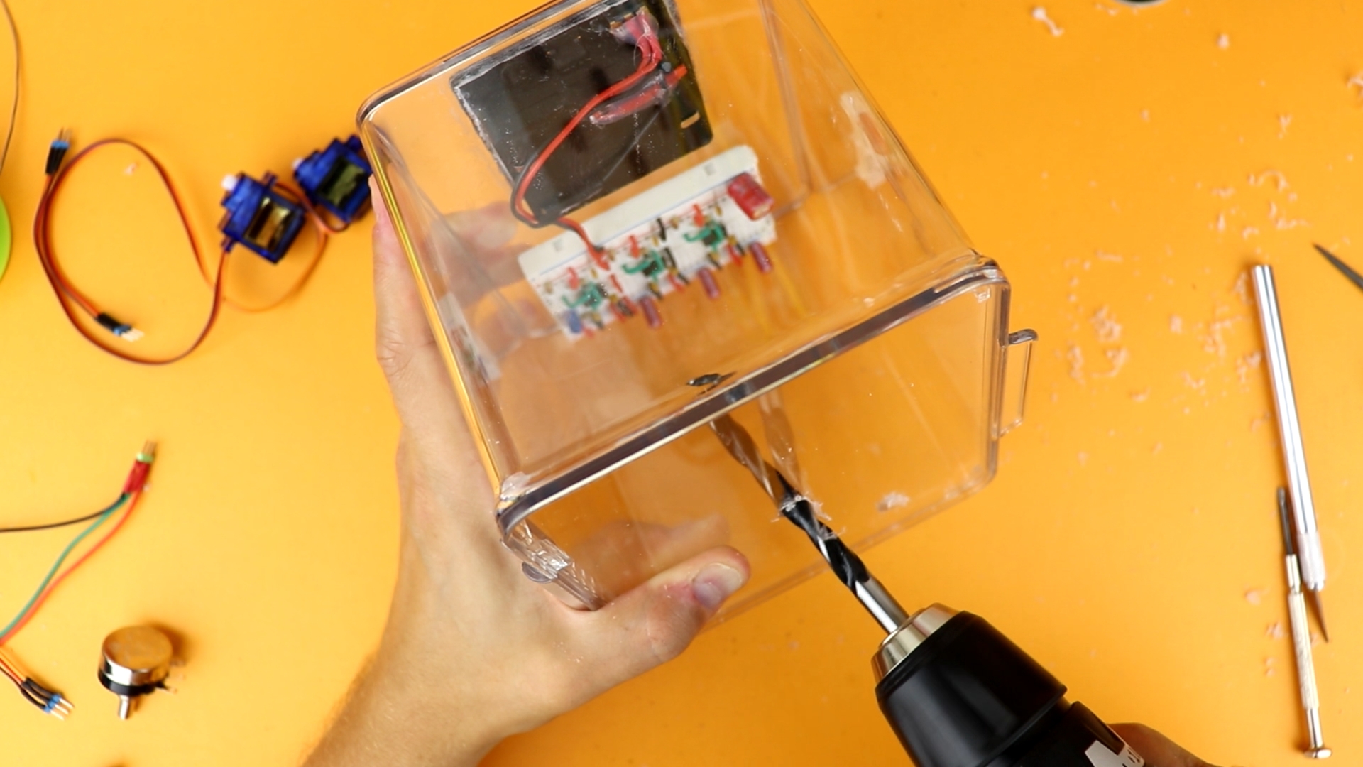
I started by creating a cutout for the battery compartment, and then glued it in place with some E6000:

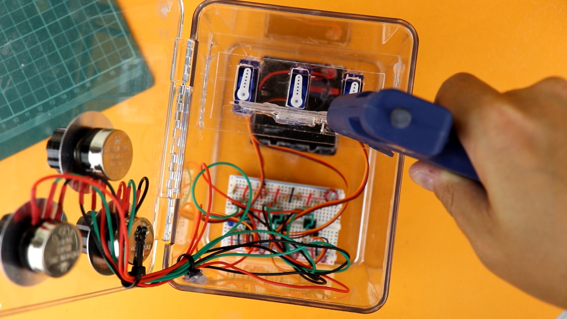
Then I placed the breadboard inside the box.
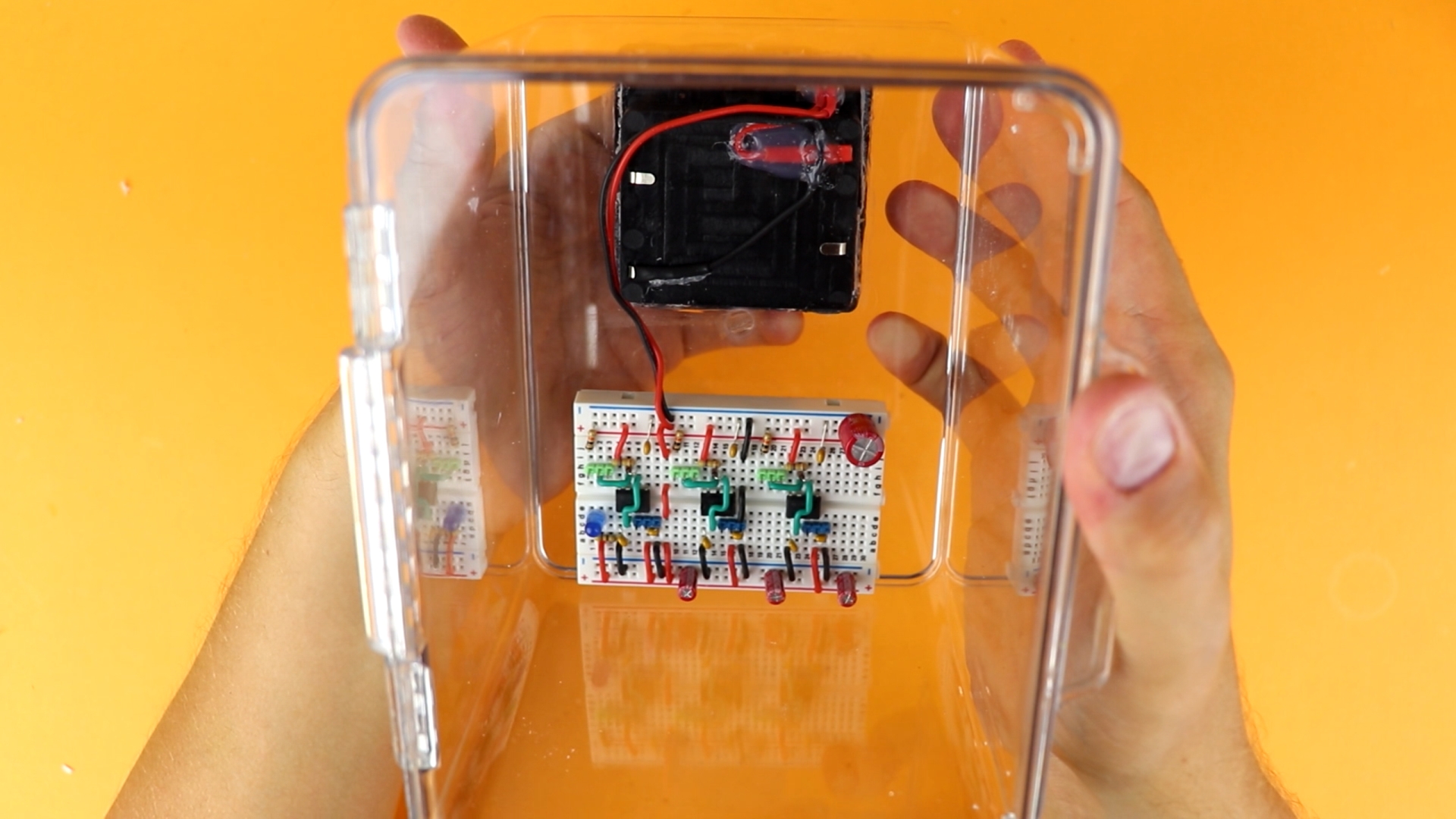
At this point I wanted to make sure that everything works, so I plugged in a servo and a potentiometer and gave it a test. And yes, it worked :)
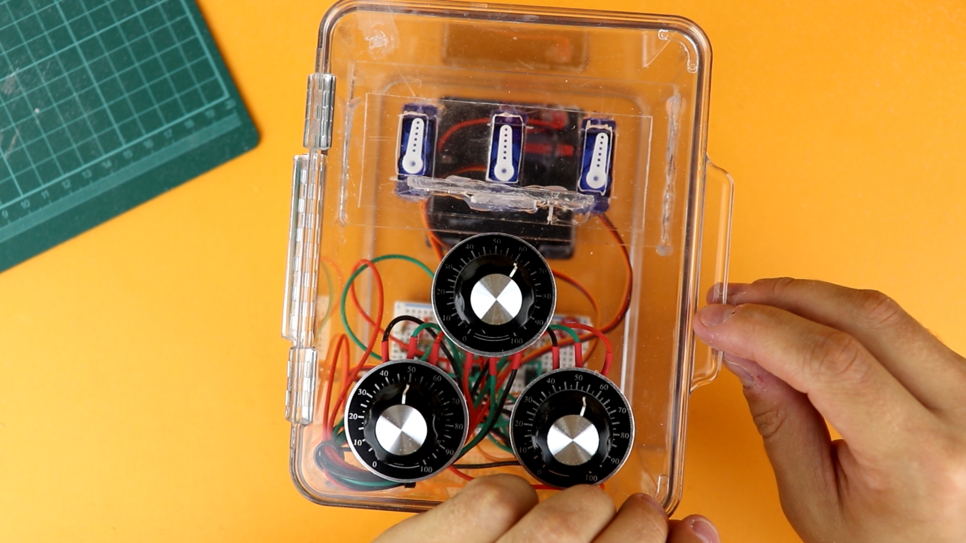
Now it was time to drill the holes for the potentiometers. I used increasing drill bit sizes (from 3mm up to 9mm) with plenty of WD40 as a lubricant. Not pressing down the drill very strongly also helped. Be patient, and it will work out great!

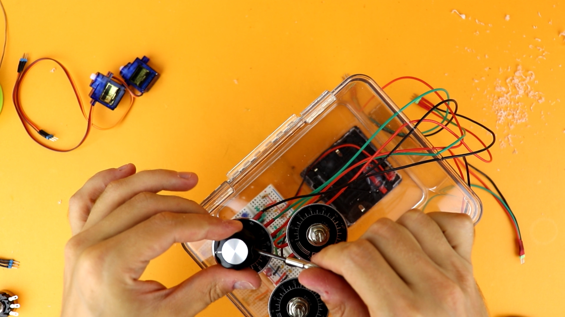
I think they look very sleek:

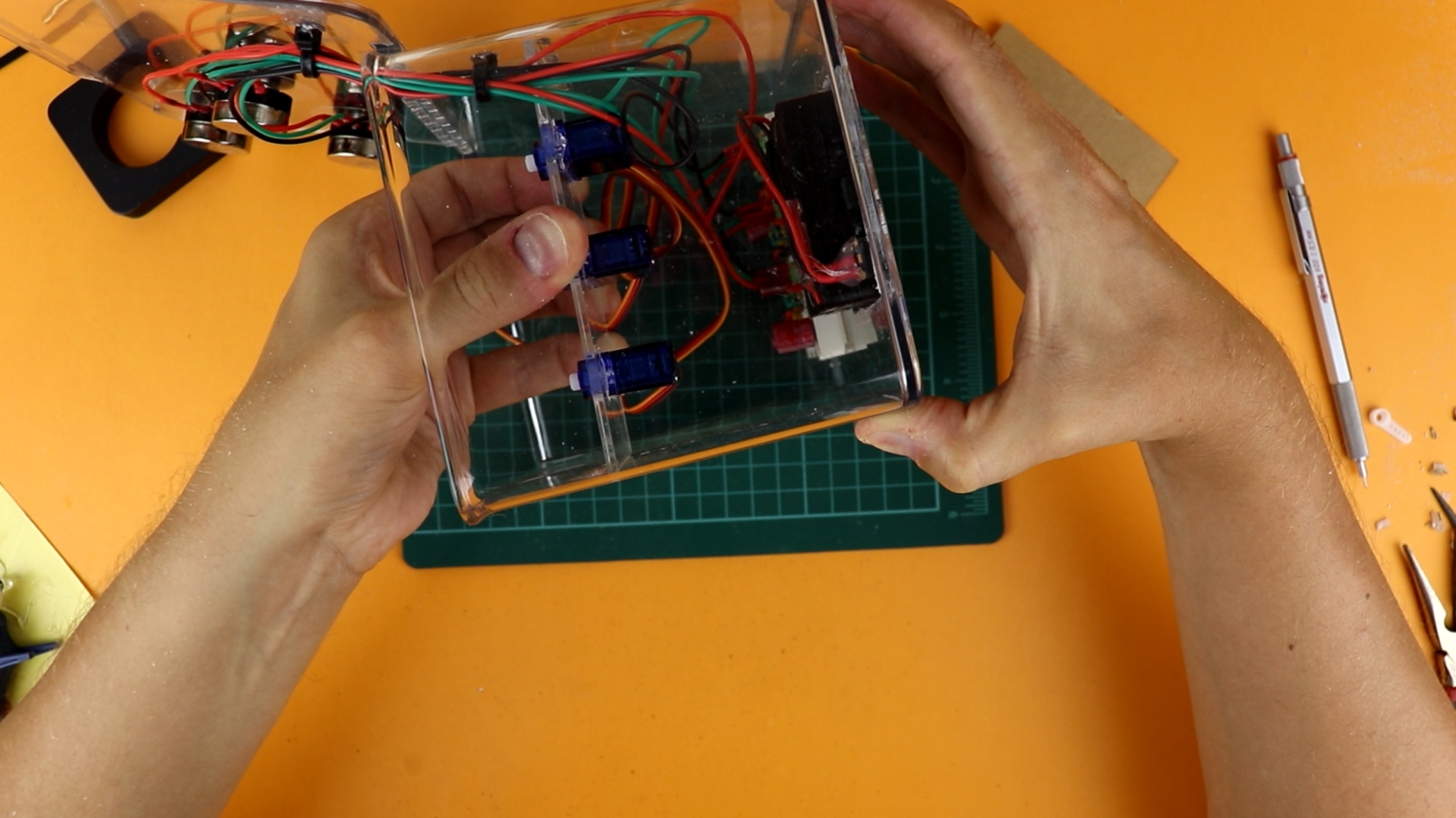
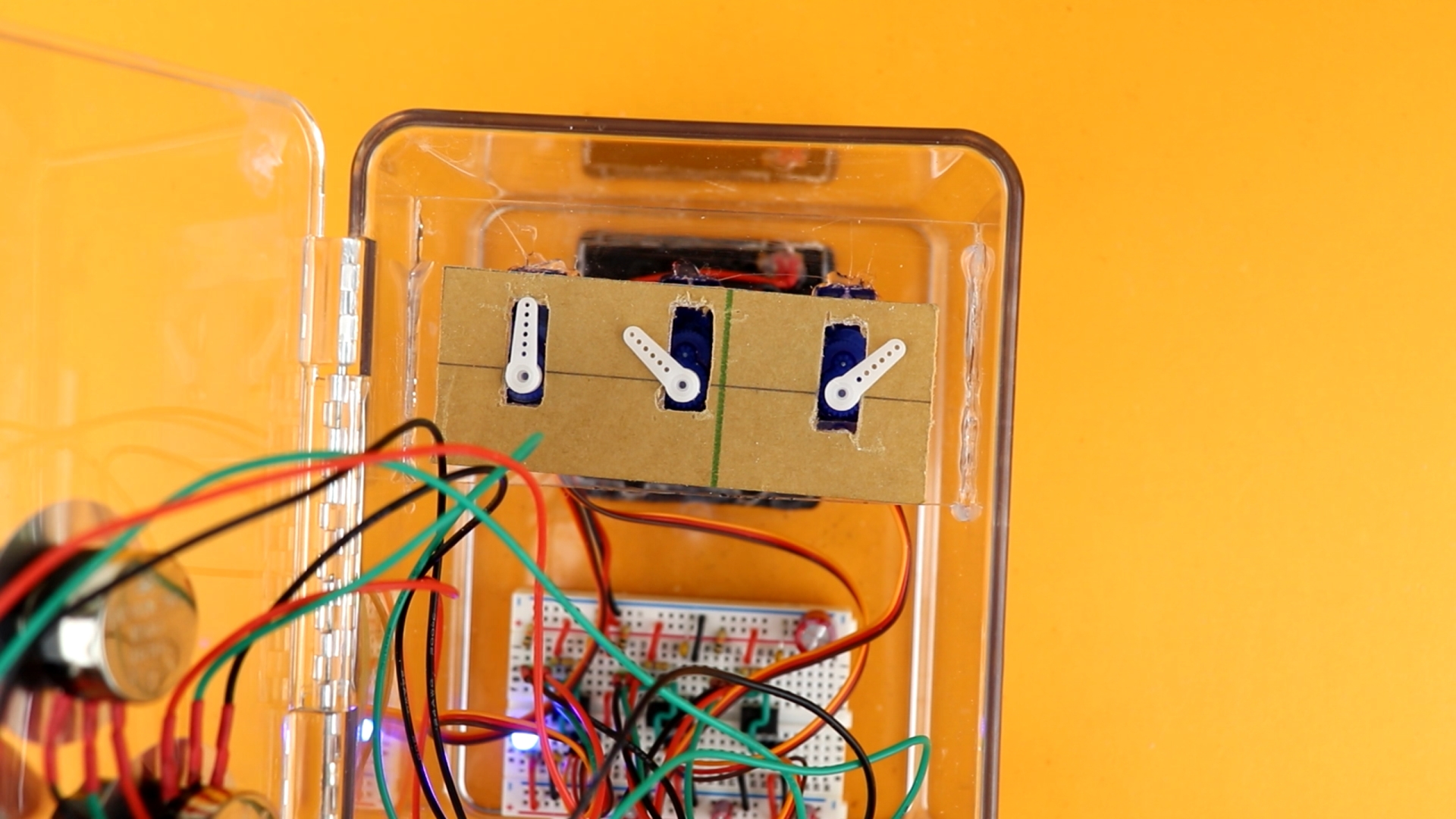
To mount the servos, I made a simple bracket out of acrylic using my rotary tool (and files):
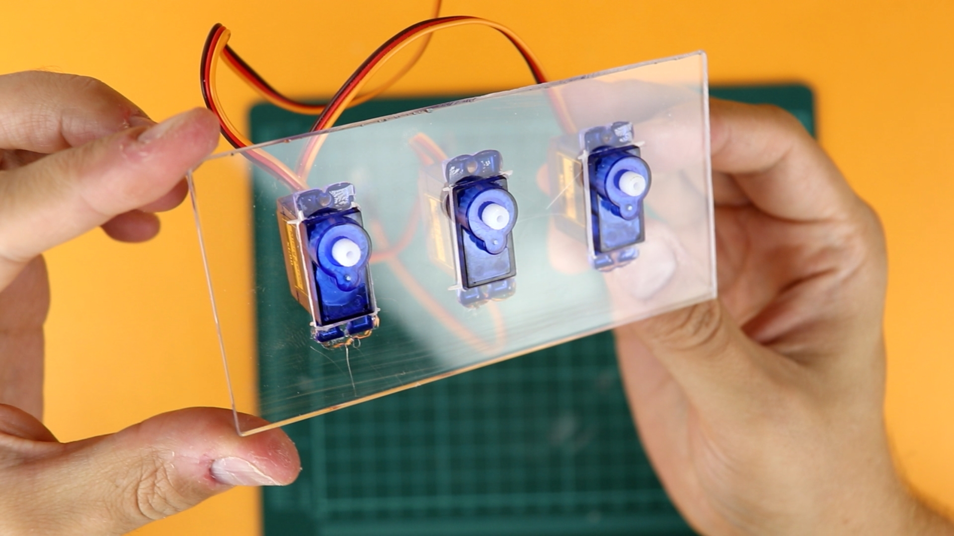
I left it a bit wider so that it would friction-fit inside the box, and I only had to use a bit of hot glue to keep it in place:
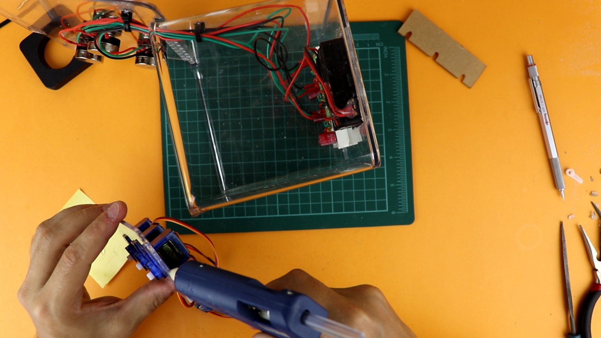
And, while I was in there, I also used some zip-ties to organize the cables a little bit to keep them out of the way:

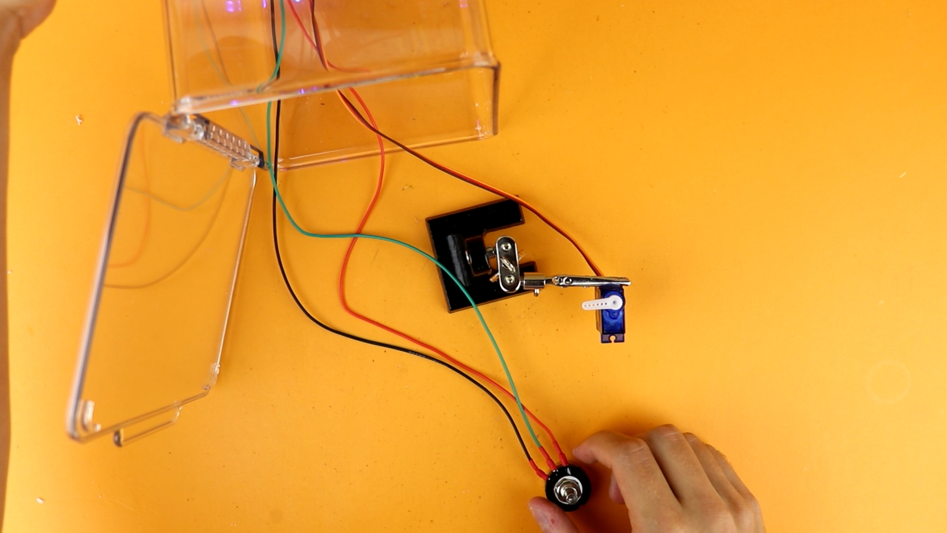
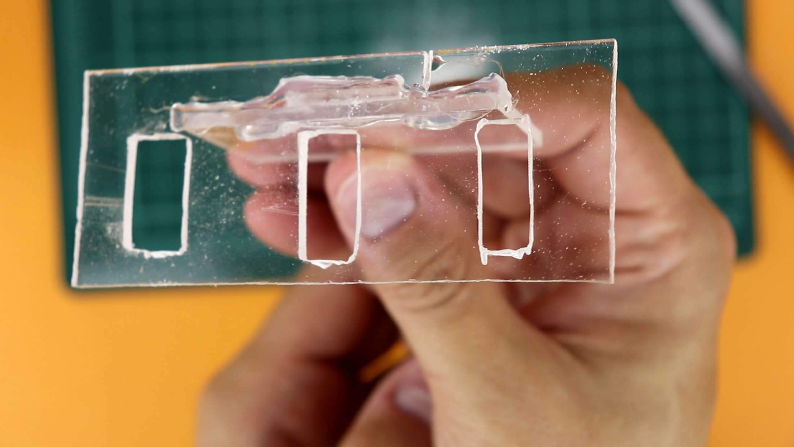
Now for the trickiest, but also most important part of the build: the lock! Here is the acrylic cutout:
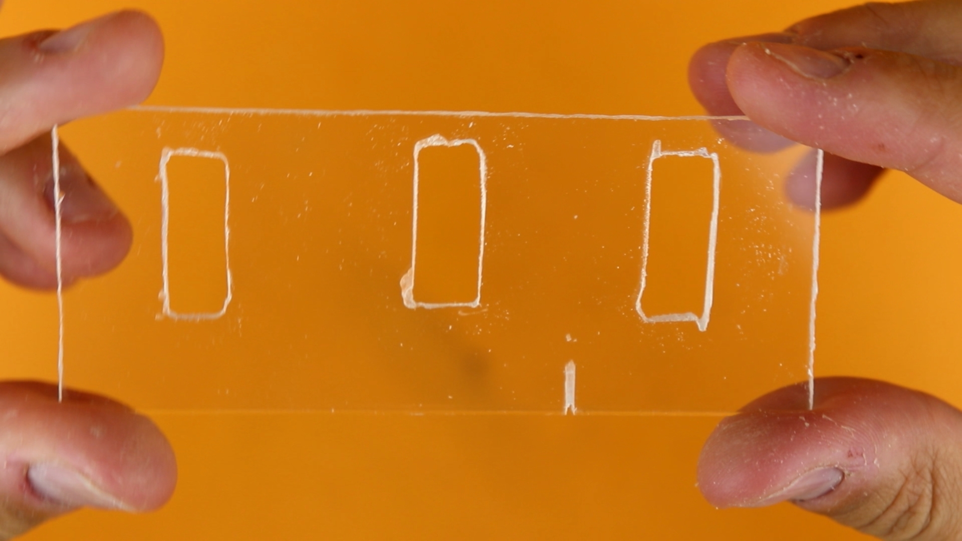
The idea is to fit this around the servo arms, like this:
Then, when the arms turn to different positions, they will lock this plate in place. And if we attach this plate to the door, the door itself will be kept in place. This is how the resulting bracket looks like:
Now how to glue all of this into the right position? I decided to place it in the correct position, add enough hot glue, and then close the lid. This glued it into exactly the right spot!
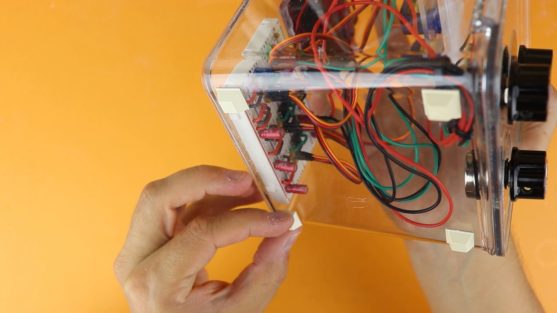
And I also added some feet, so that the safe has some clearance to the ground it sits on, which made it easier to open the door:
At this point, the safe was done. Well, I had to do a bit of filing to make sure that the lock clears the servo arms when the door hinges outwards (yes, angles can be confusing and deceptive). But in the end, it worked just fine :)
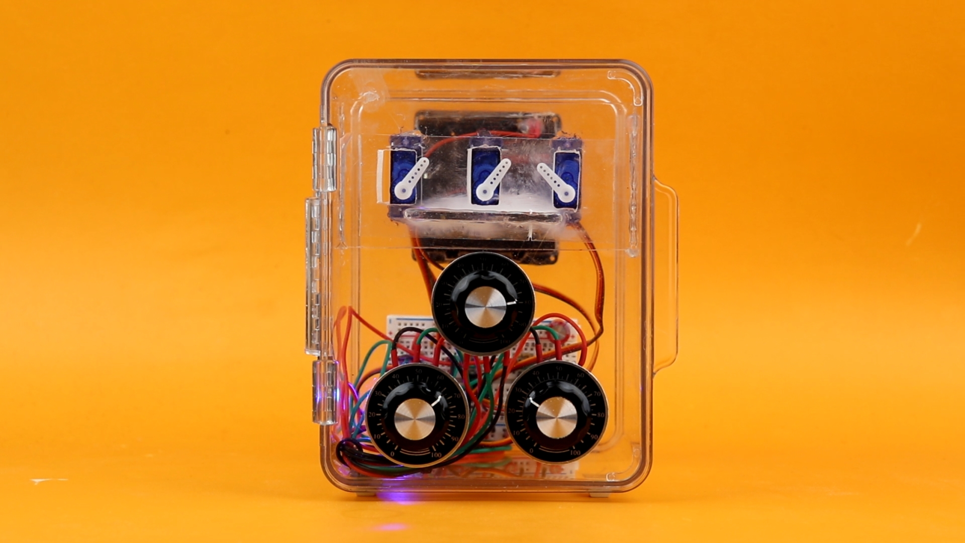
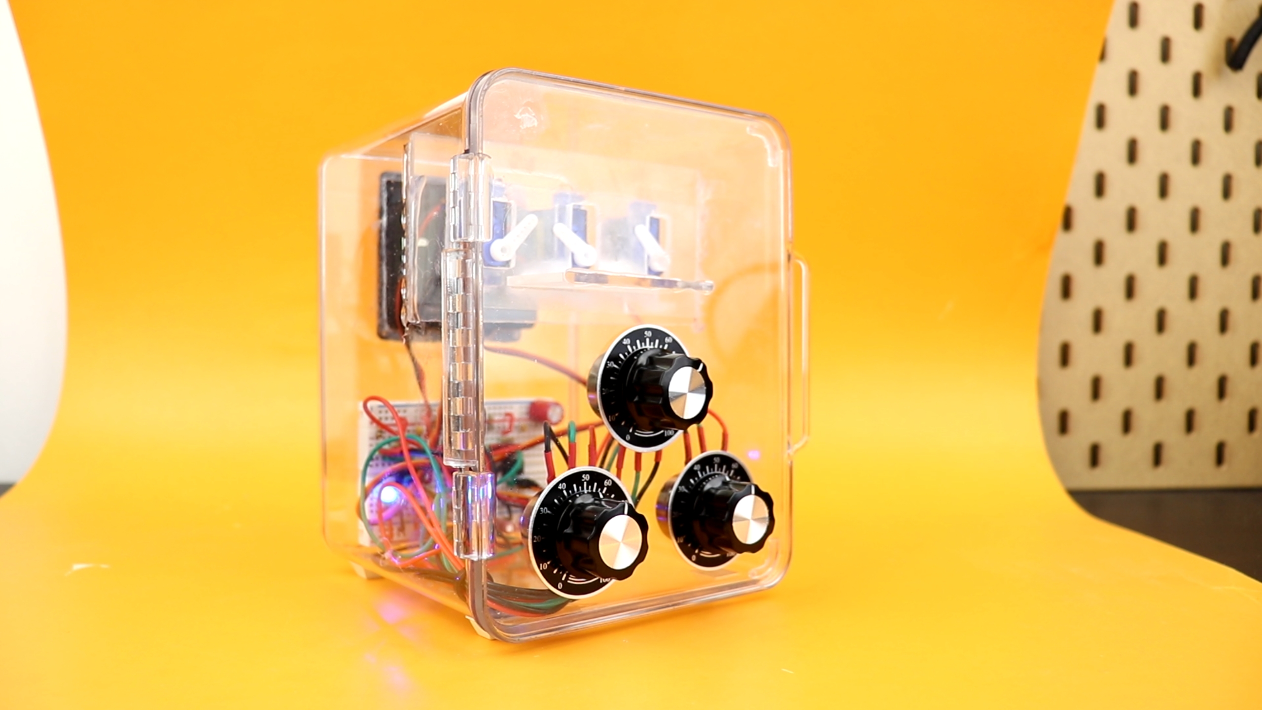
Finished NE555 servo safe
So the safe works, and we can open and close the door. All is great, isn't it?
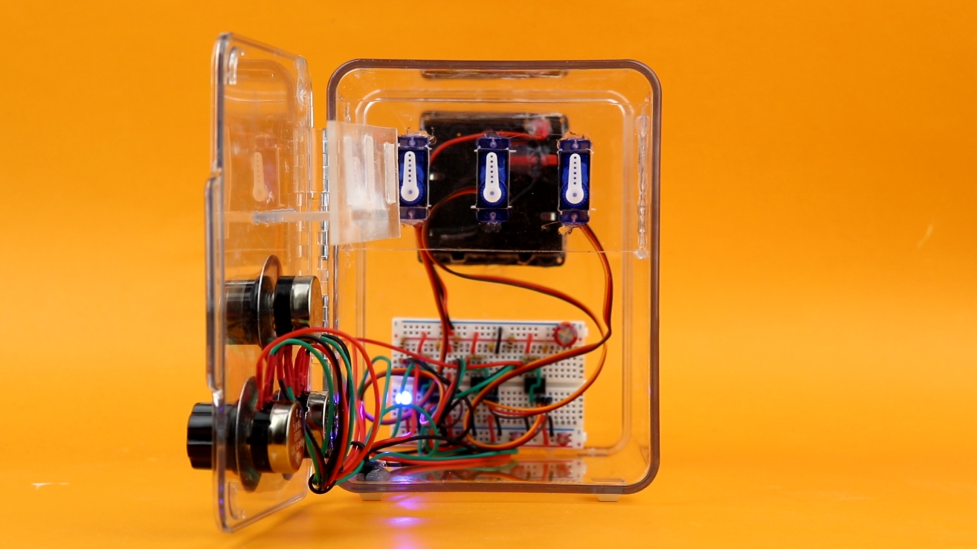
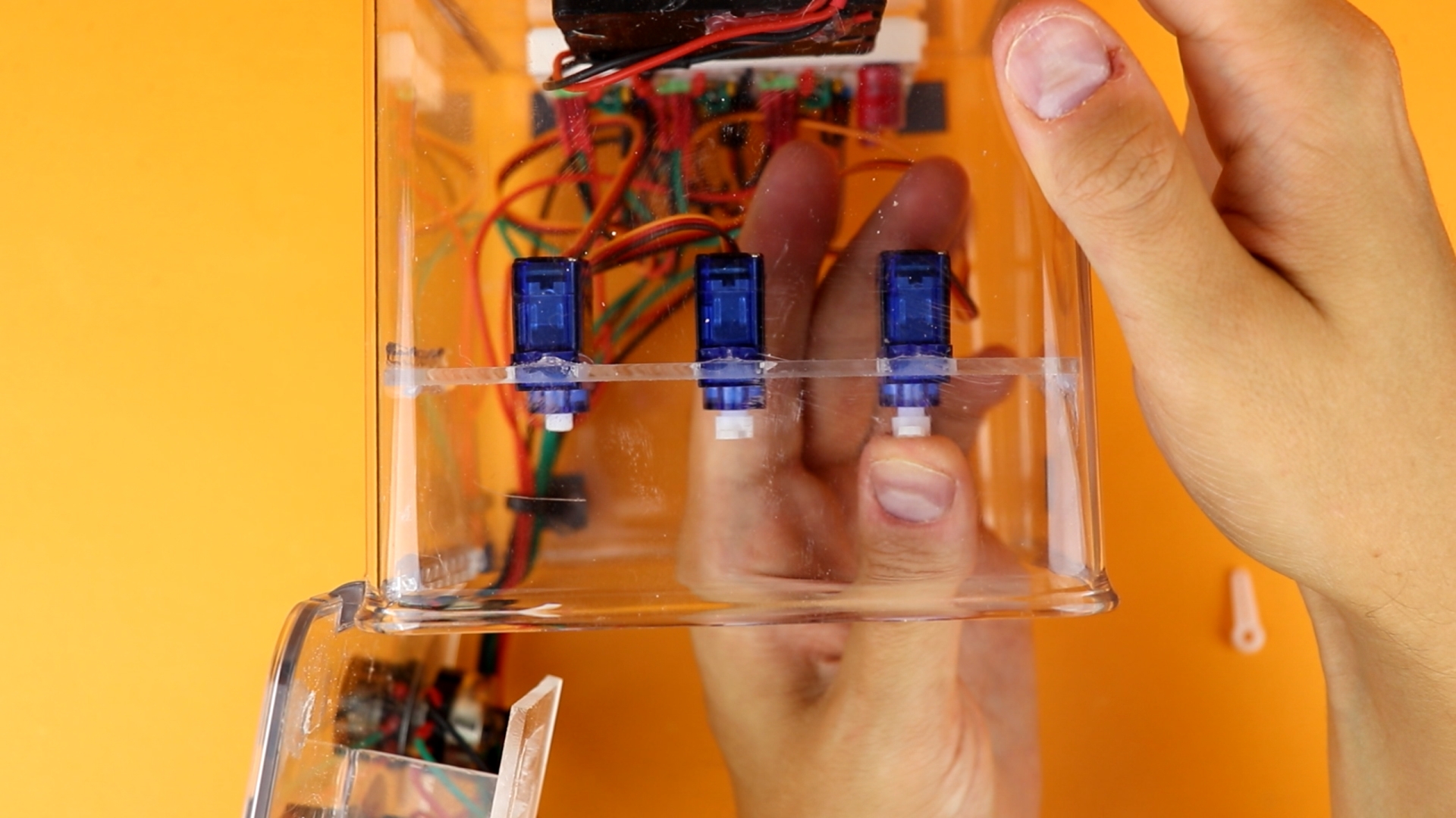
Well, almost. Every safe has a unique combination. So how do we set the combination here? The answer is quite simple: first, we have to remove the servo arms:

In a second step, we can then turn the knobs to any position we like. This will be the new code. Then, simply reattach the servo arms, so that they point upright. And that's it!
Now I should mention that not all codes are possible with the type of lock I constructed in this build. There can be some mechanical interference with the servo arms. But this is not a problem with this method of lock, I just dropped the ball there. So if you are building this yourself, make sure your servod have an allowed range of 360 degrees (and not just 180 degrees, as in my case).

YouTube video
I covered this entire project in a dedicated YouTube video:
Final thoughts
Congratulations! You are now the owner of a brand new safe! Building this was a lot of fun, but it also took way longer than I thought because acrylic is so much harder to work with than wood. But I think it was totally worth it, and I love this little safe!
I think this safe is an ideal beginner's project, and if you want to see if electronics is for you I can only hope that I inspired you to give this a try yourself. And remember, if something doesn't work, or if anything in this video doesn't make sense, let me know on social media, and I will do my best to get back to you. Thank you so much for reading, and I will see you next time!


