Building an analog clock with a microcontroller
April 30, 2022 • project
Microcontrollers are digital devices, but in this project we will turn it around and use a PIC microcontroller to build an analog clock using a panel meter. And what's more, we will make use of the SLEEP mode of the PIC microcontroller so that this circuit can be run off of batteries and keep the time for decades when not powered on.
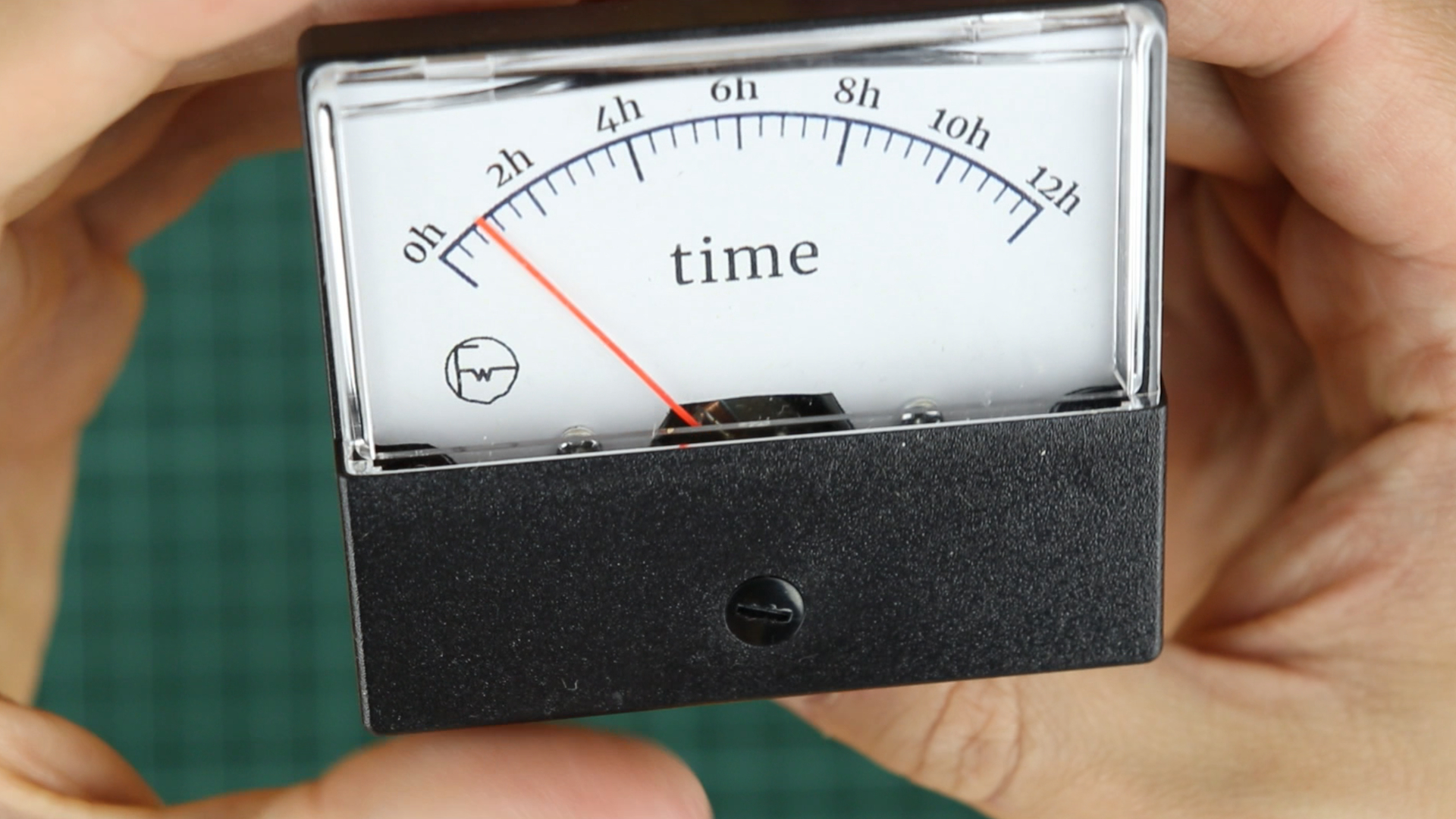
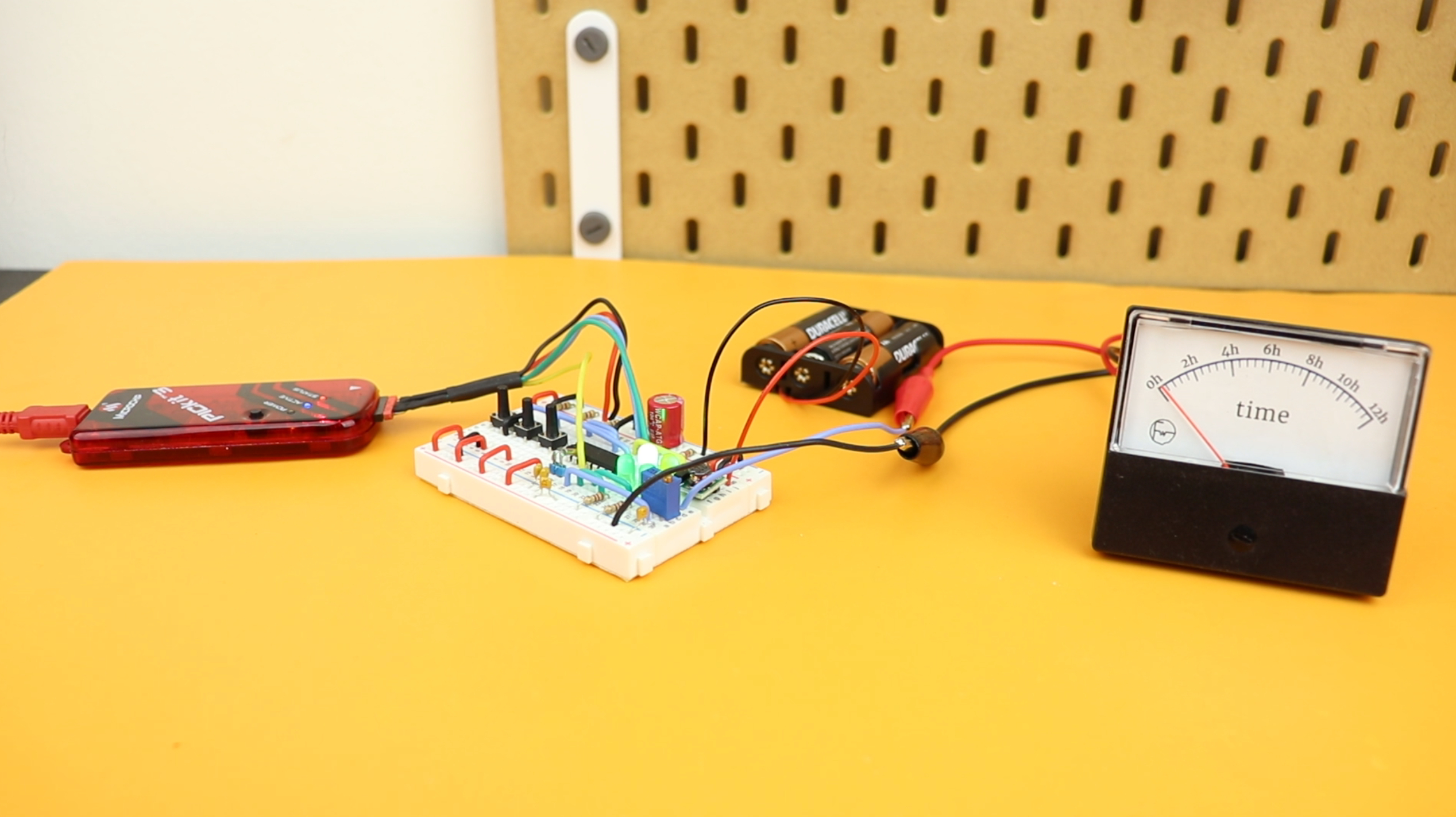
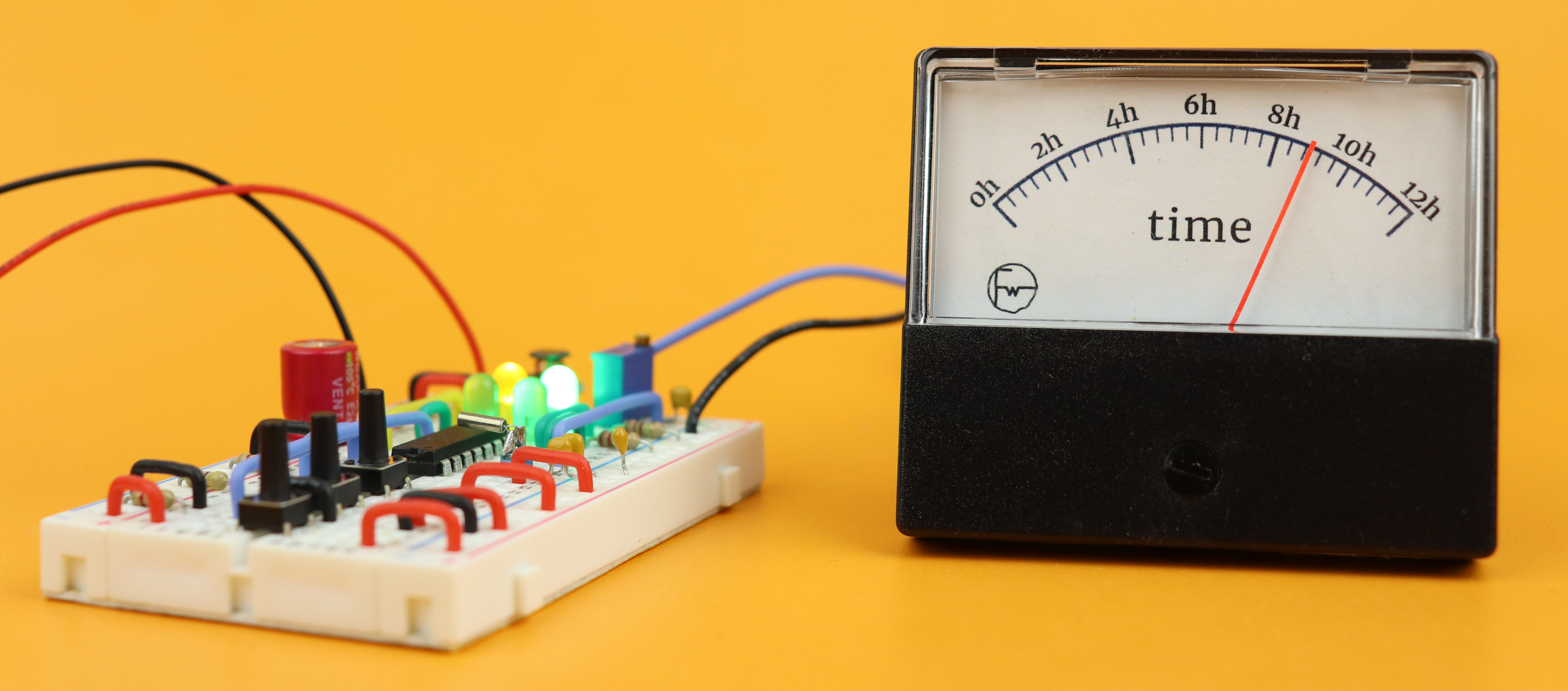
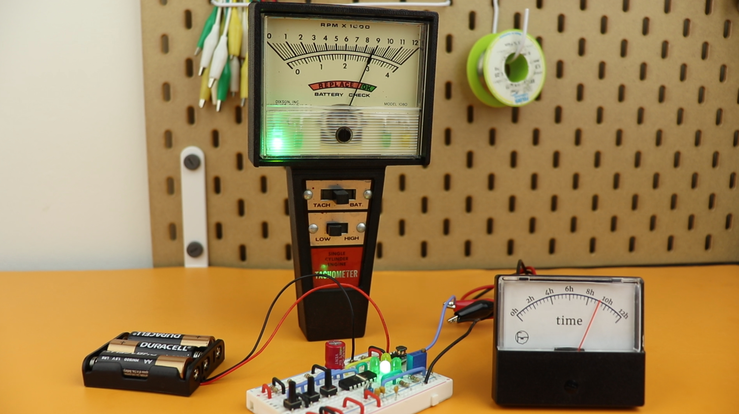
And to give you some idea, here is how the finished clock looks like:
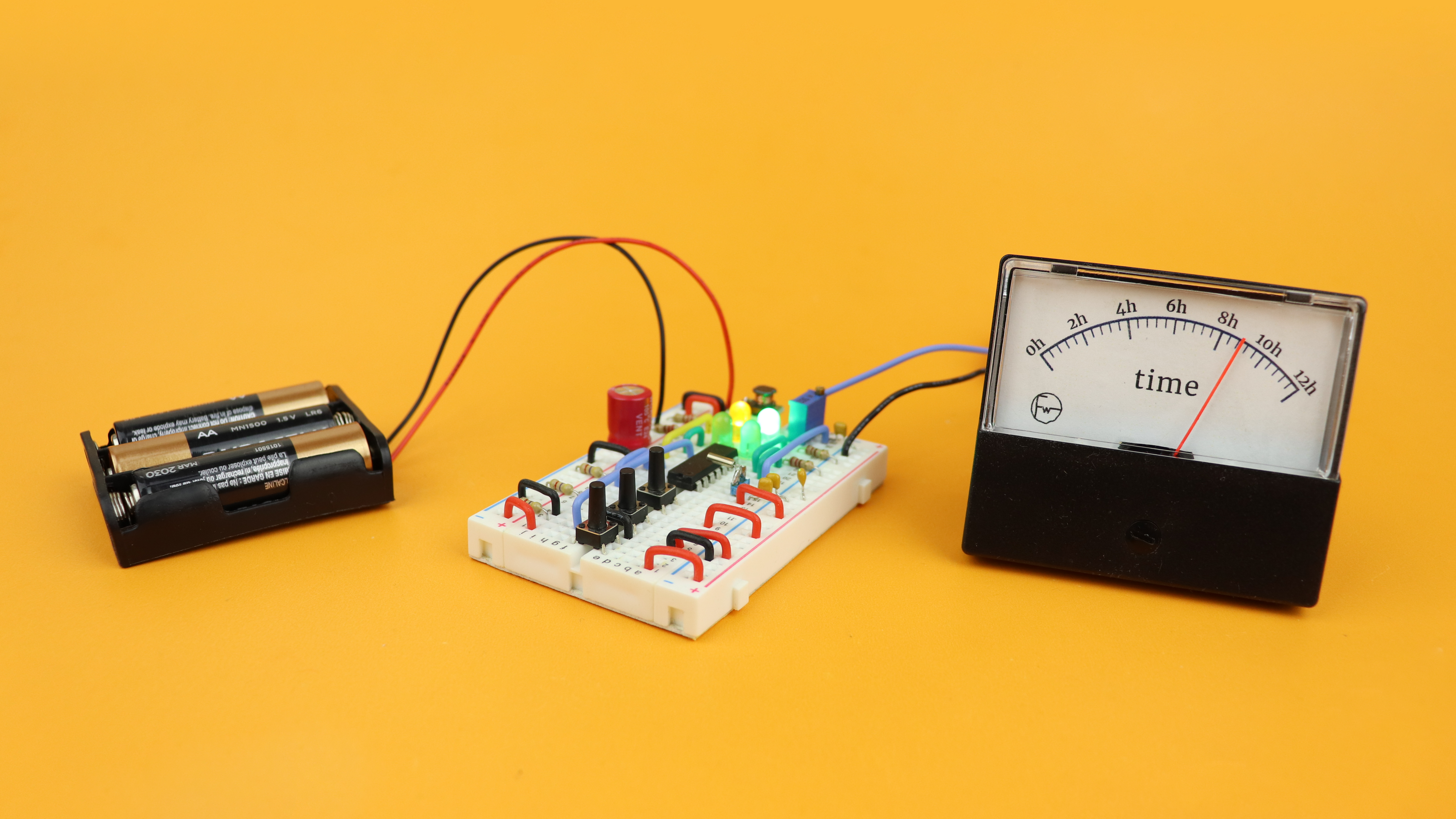
The panel meter shows the time, here from 0 to 12, and a yellow LED on the breadboard tells us whether it is PM or not. The three pushbuttons on the breadboard are used like this:
- ON/OFF: The leftmost button turns the clock off or on. When it is off it still keeps the time, though, because the microcontroller goes into an ultra-low power mode that is also called sleep mode, and we will talk much more about it later.
- UP: Pushing the middle button increases the time.
- DOWN: And yes, you guessed it, pressing the rightmost button decreases the time.
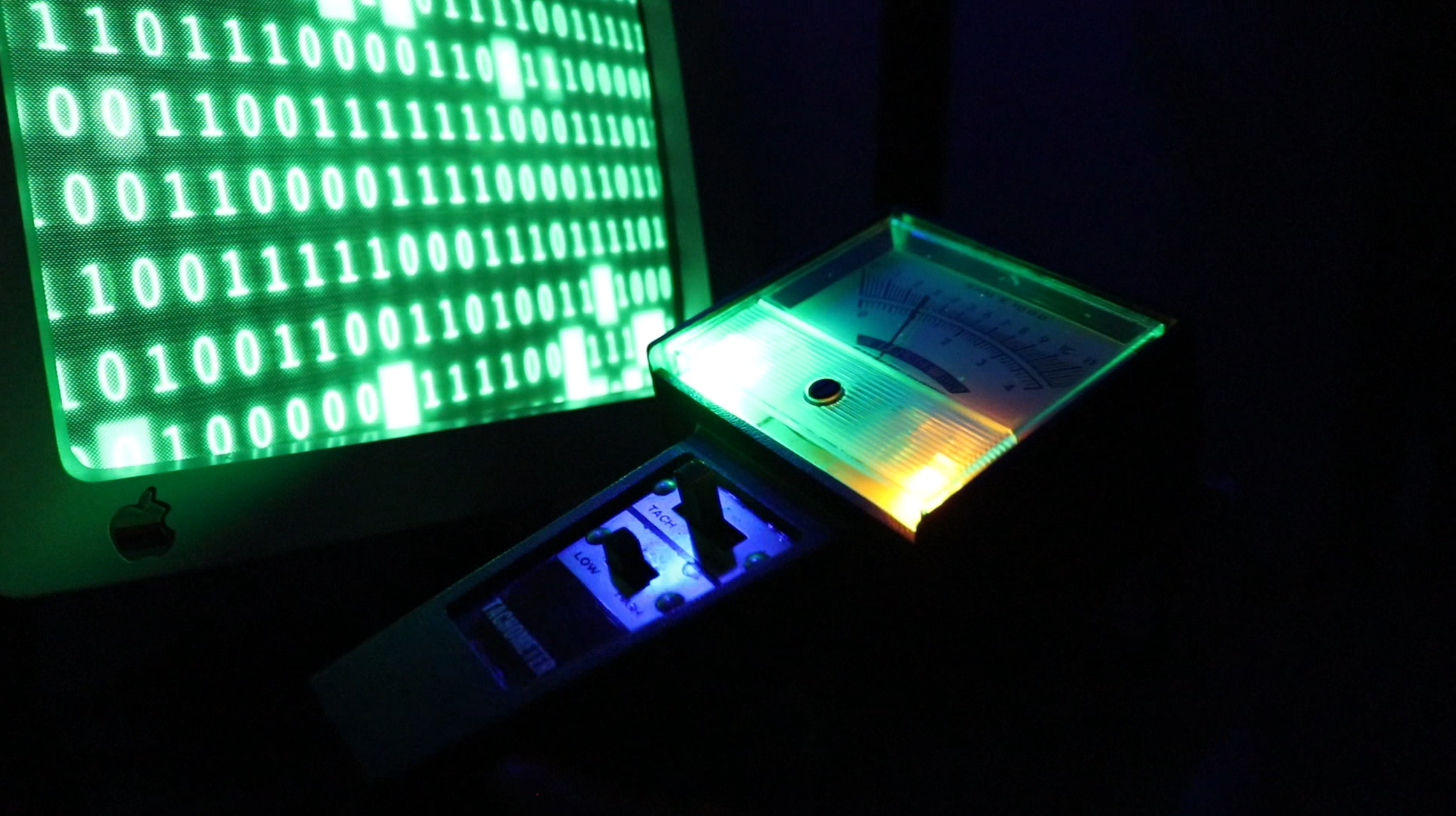
And in the rest of this article we will go through everything in much more detail: what components you need if you want to build this clock by yourself, how to program the microcontroller, and in the end I will also show you how I converted this from a breadboard project into a real-life clock that definitely gives off some Ghostbusters vibes. Let's go!


What you need
As always, let's first go through the components that are needed for this project:
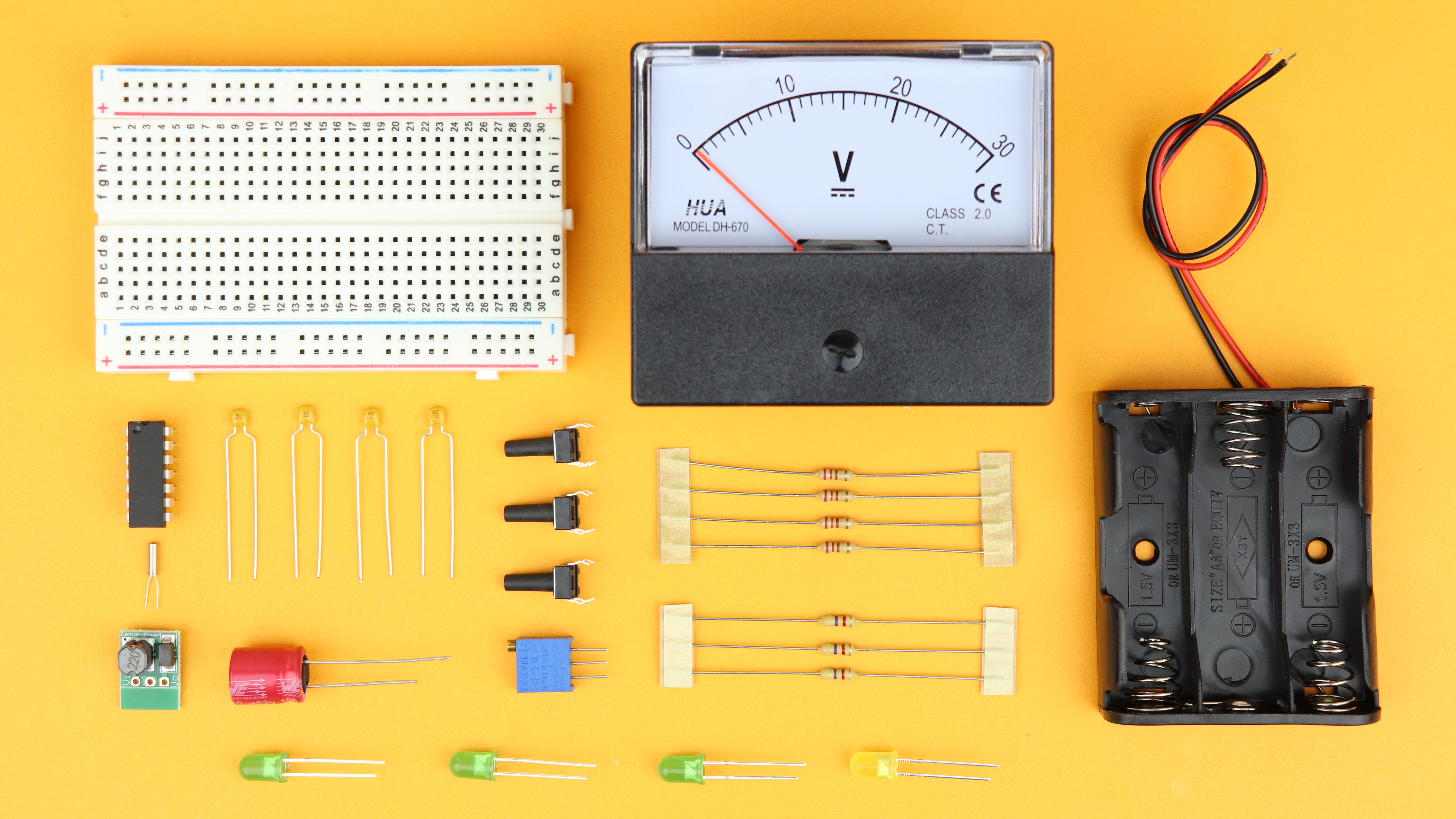
- The brain of our clock is the PIC16F1455 microcontroller. It drives the panel meter, the LEDs, and reads out the pushbuttons.
- The panel meter (here I use a 30V version) is used as the display. You can use almost any panel meter for this project, but it needs to be modified a little bit, and we talk about it in a lot of detail below.
- All of this runs off of batteries, and besides them you also need some LEDs, some capacitors, resistors, pushbuttons, and of course a breadboard.
- The time information is generated with a 32.768kHz watch crystal, and we use a ready-made DC/DC converter module to convert the battery voltage into a stable 5V.
Check out the components box for links on where to buy all of these components.
Main idea
And before we get into the weeds of the schematic and the microcontroller programming, here is the main idea of this project broken down into main parts:
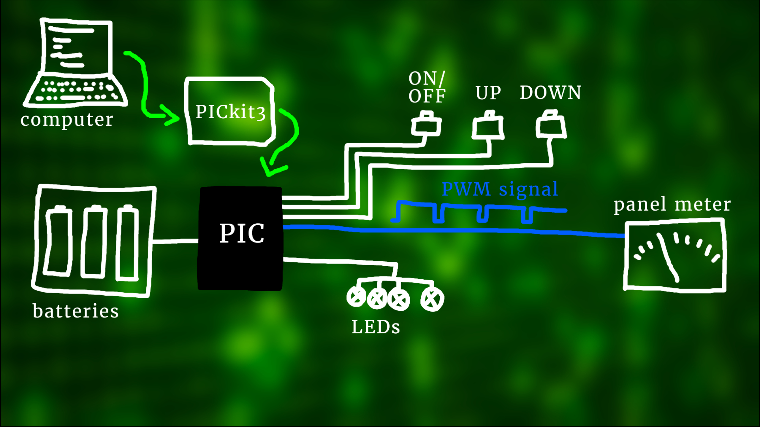
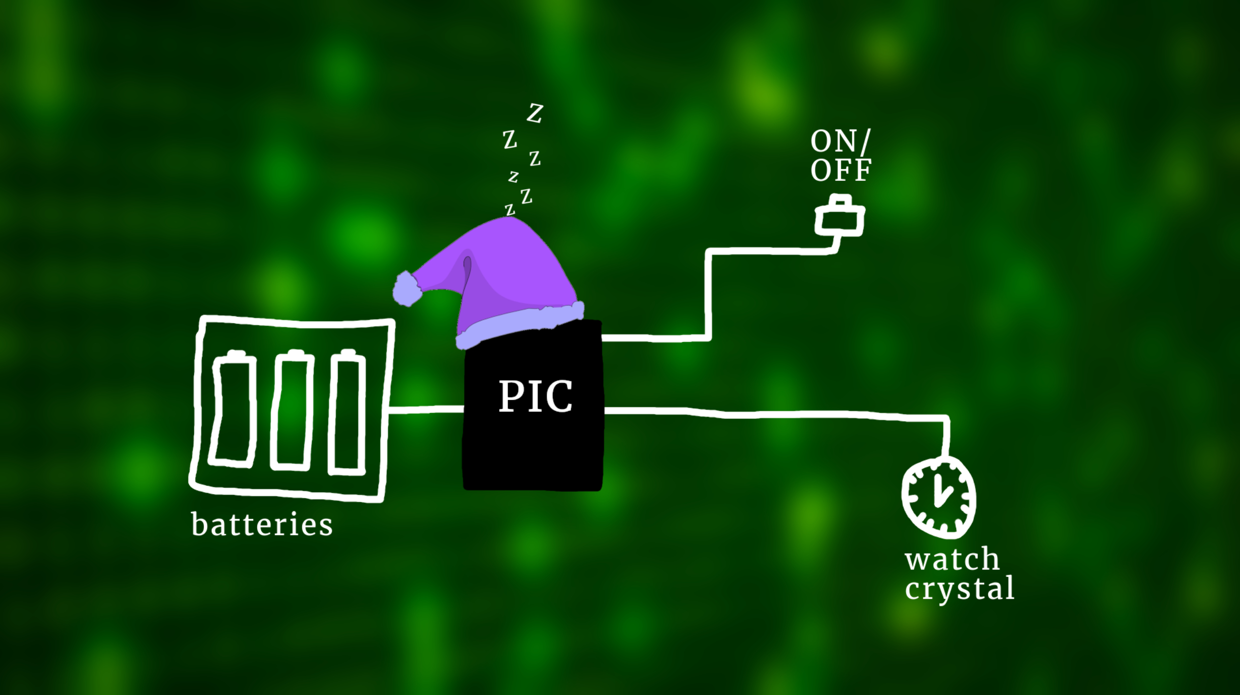
The star of the show is the panel meter that is supposed to tell us the time. And we drive that panel meter with a voltage from our microcontroller using so-called pulse width modulation (the blue line).
The microcontroller also works as the brain of our clock, and it uses a special watch crystal to measure the time. The three buttons are our user inputs that we use to adjust the clock: UP and DOWN adjust the time, and ON/OFF is the power button. When the clock is OFF it will keep running in the background in SLEEP mode, more on that later. And the four LEDs give us some additional readouts. All of this runs on batteries so that we can take this clock with us wherever we like.
But of course, this being a microcontroller project, we have to tell the microcontroller how to do all of that, and that's why we also need to write a program, and we will get into that a bit later.
We write this program on our computer, and to get it onto the microcontroller we need to hook it up to the computer with a so-called programmer. And if this is your first time meeting a microcontroller, don't worry, I have you covered. You can check out this introduction article right here, and I have many other articles and videos on this channel that will get you set up in no time!
Schematic
And if we squint our eyes a little bit, the picture that we looked at above looks almost identical to the schematic:

The PIC16F1455 microcontroller is in charge of everything. It controls the four LEDs, reads the status of the three pushbuttons, and it uses the 32.768kHz crystal here to create a 1-second timebase so it can work as a clock. It also outputs a pulse-width modulation signal here that we feed to the panel meter.
The 5kΩ potentiometer R8 is used to calibrate the maximum position of the panel meter's needle, and together with this 100nF capacitor C5 it also works as a so-called low-pass filter. This filter turns the digital PWM signal, that looks like this, into a smoother signal like this. The time constant of this filter is around 1ms, which works well with the PWM frequency of around 4 kHz.
Let's talk about power. The three AA batteries run this circuit, and their voltages add up to 4.5V in total. But when in use the batteries get older, and their voltage becomes lower, so it will be only 4.4 V at some time, then 4.3V, and so on. We need to make sure that we can always generate a stable maximum voltage for the panel meter, because otherwise the position of noon—which is the maximum position on the right—would change on the panel and shift from 12 towards 11.
The solution is simple: IC2 is a DC/DC stepup converter that takes a voltage from 1-5V and converts it into a fixed voltage of 5V, which is super handy. You can buy these as ready made modules. And the two capacitors C1 and C2 are just there to stabilize the circuit.
Last, the PICkit3 programmer is connected to the PIC16F1455 on the master clear, program data, and program clock pins, and we also need to connect it to VDD and ground.
Building the circuit
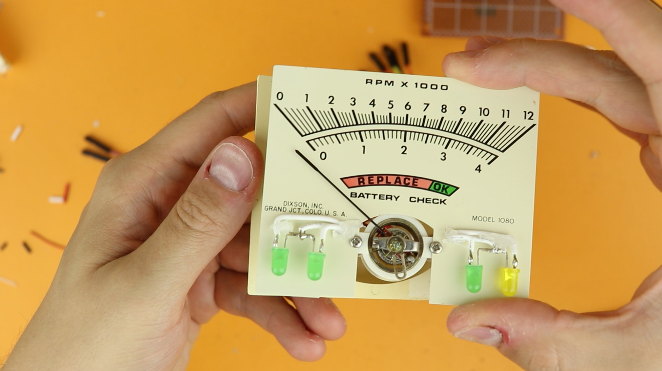
So now we are basically ready to build this circuit... almost! The only thing left to do is to prep our panel meter. I will show you how to do it for the 30V version that I am using here, but you will see that it's very easy to do for other panel meters as well.
I have a detailed article on panel meters that you can check out for additional details. In a nutshell, there are two important values: the resistance of the coil itself, and I call that Rint, and the current at which the panel meter maxes out, and I call that the saturation current Isat. For most voltmeters there is an additional external resistor Rext that calibrates the panel meter to a required voltage. Here is a picture of the voltmeter I am using for this project:
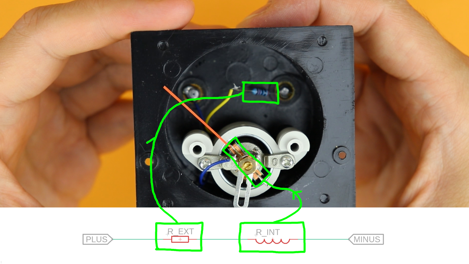
It's a 30V voltmeter, so there is some extra resistor. Measuring these values I find that Rint = 250Ω, Rext = 29.75kΩ, and Isat = 1mA. Here is how that all works out, using Ohm's law:
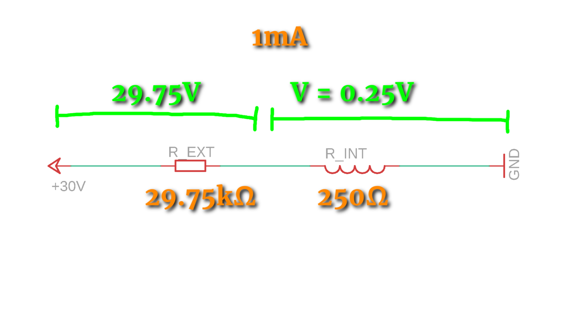
But if we want the display to max out at 5V instead, then we need to adjust the external resistor to around 4.75kΩ:

And that's why the resistor R8 in the schematic is a multi-turn potentiometer of 5kω: this way we can precisely adjust it to the point where the scale maxes out at 5V exactly.
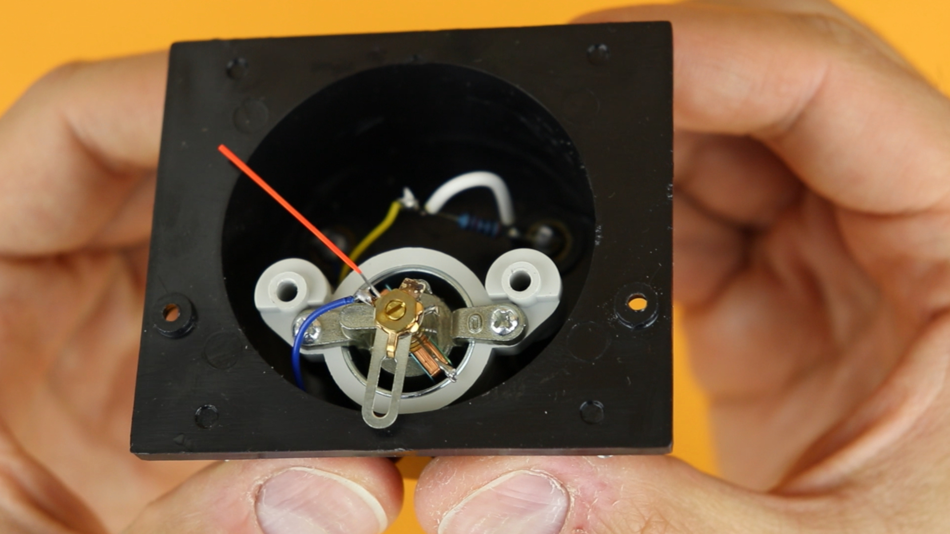
And in our case we have this external resistor on the breadboard, so all I did for this multimeter here is to bridge the external resistor with a wire:
The last thing I did was cosmetic: I scanned the original panel meter's scale and edited it, so that it now shows the time properly. This is how it looks like (download it here):
Then I closed the panel meter back up again, and with that out of the way we can finally start building the circuit!
-
-
Step 1
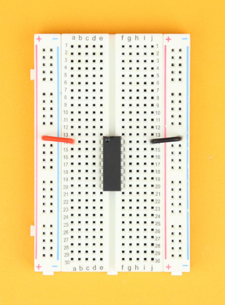
Place the 400-pin breadboard in front of you, with row 1 facing to the top.
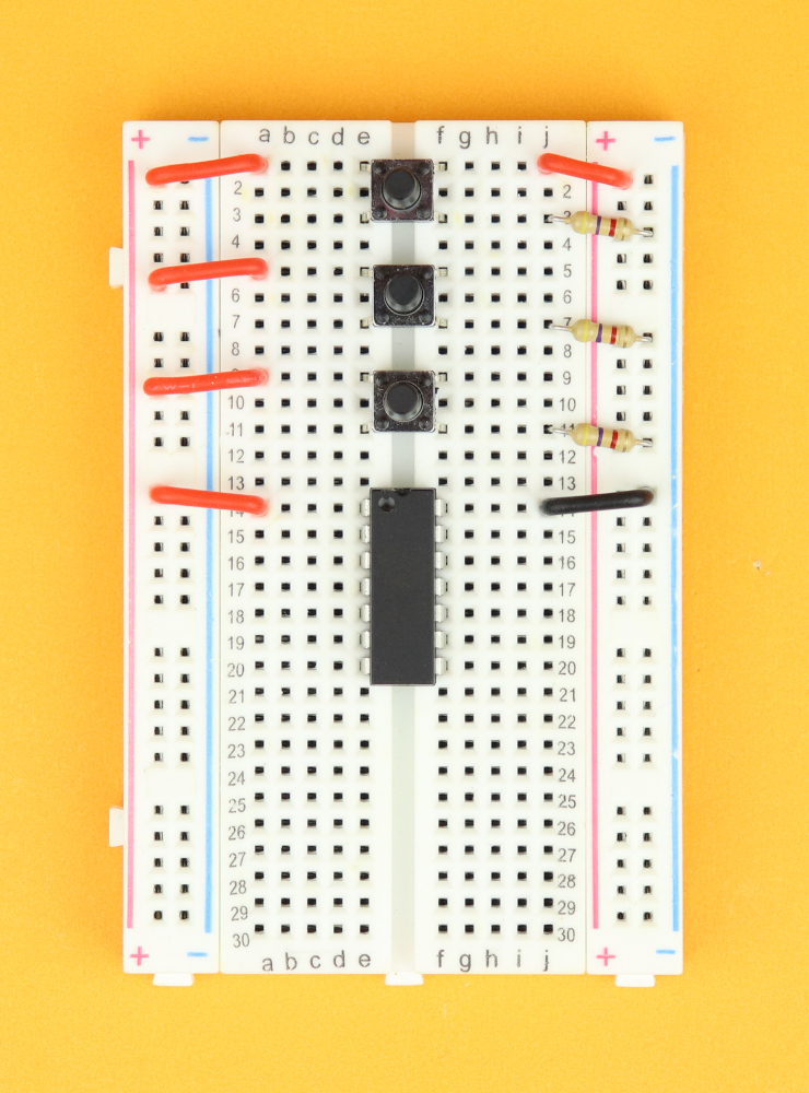
Insert the PIC16F1455 in row 14, and connect pin 1 (top left) to the positive power rail, and pin 14 (top right) to the negative power rail.
-
-
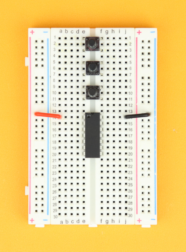
Step 2
Insert the three pushbuttons in rows 1, 5, and 9.
-
-
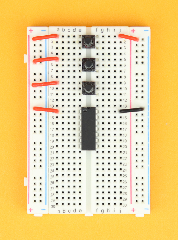
Step 3
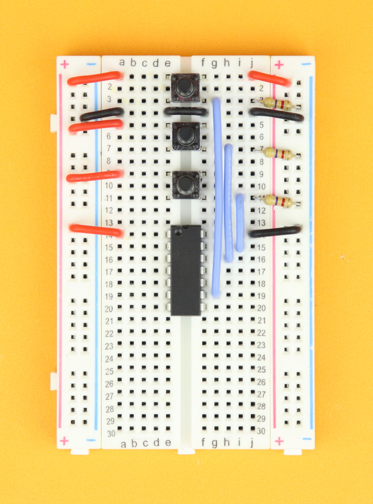
Connect the top left terminal of each pushbutton to the positive power rail. Connect the top right terminal of the upper pushbutton to the positive power rail on the right side of the breadboard.
(This makes sure that the positive power rails on either side of the breadboards are connected.)
-
-
Step 4
Next, insert the three 4.7kΩ resistors R5, R6, and R7 between the bottom right terminals of the pushbuttons and the ground rail.
-
-
Step 5
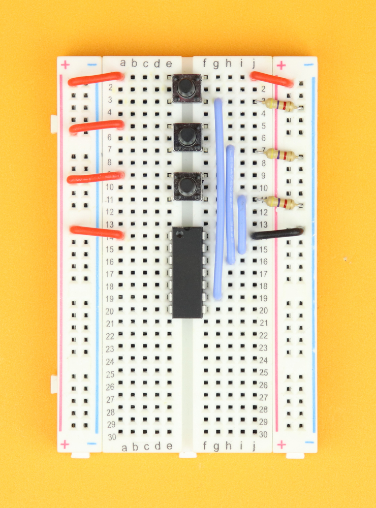
Connect the upper pushbutton to pin 9, the middle pushbutton to pin 12, and the lowest pushbutton to pin 13.
-
-
Step 6
Now it's time to make sure that the ground rails on either side of the breadboard are also connected to each other. Insert wires from the left ground rail to row 4, from row 4 on the left across to row 4 on the right, and from that row into the right ground rail.
-
-
Step 7
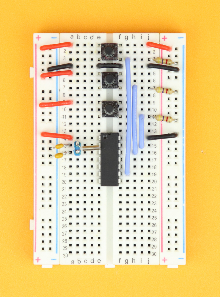
Insert the 32.768kHz watch crystal between pins 2 and 3 of the PIC16F1455, and insert the two 22pF capacitors C3 and C4 from each leg of the crystal into the ground rail.
Tip: I soldered the watch crystal to a two-terminal pin header, which makes it a lot easier to reliably insert the fragile wires of the crystal into the breadboard.
-

-
Step 8
Insert the four LEDs in rows 22 and 25 on either side of the breadboard, with the cathodes facing towards the bottom of the breadboard. Next, connect the cathodes to the ground rail with the 220Ω resistors R1–R4.
-
-
Step 9
Connect LED1 to pin 6, LED2 to pin 7, LED3 to pin 8, and LED4 to pin 10.
-

-
Step 10
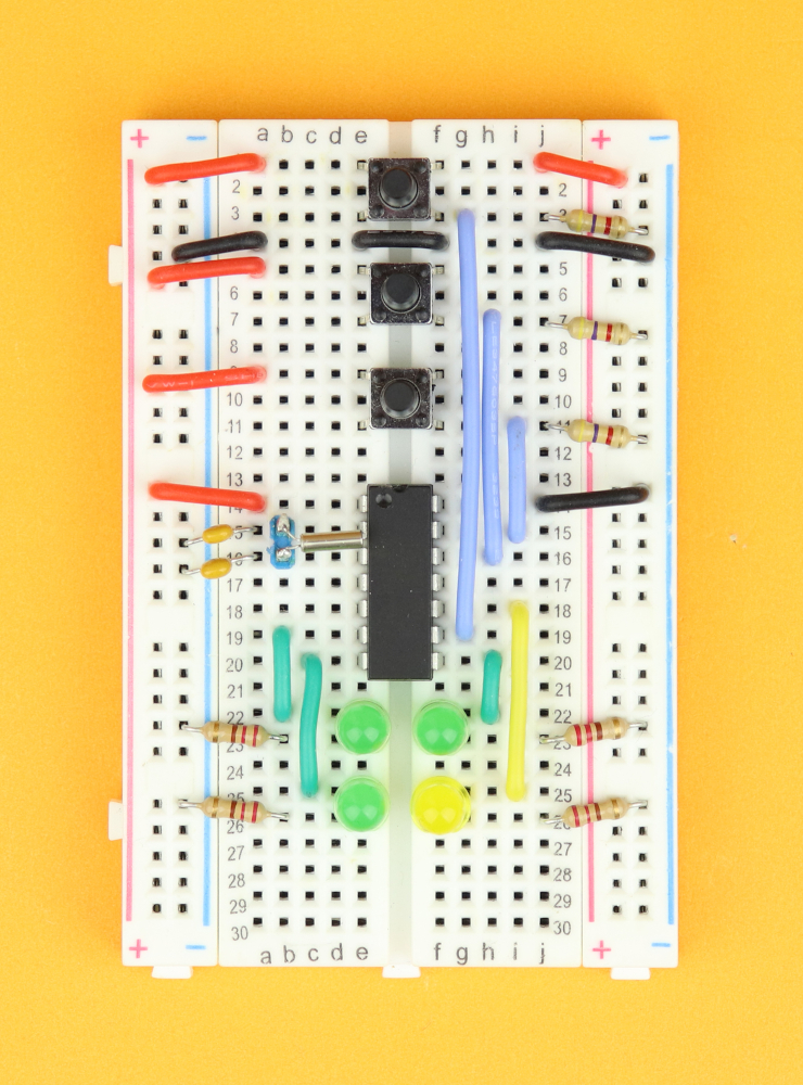
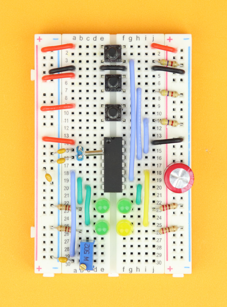
Connect pin 5 down to row 29, and insert the potentiometer in row 28 (so that the wire from pin 5 is connected to the center pin of the potentiometer). Also, insert the 100nF capacitor C5 between row 30 and the ground rail.
-
-
Step 11
Place the 100μF bulk capacitor C1 and the 100nF bypass capacitor C2 in the power rail. Make sure that the polarity of C1 is correct.
-
-
Step 12
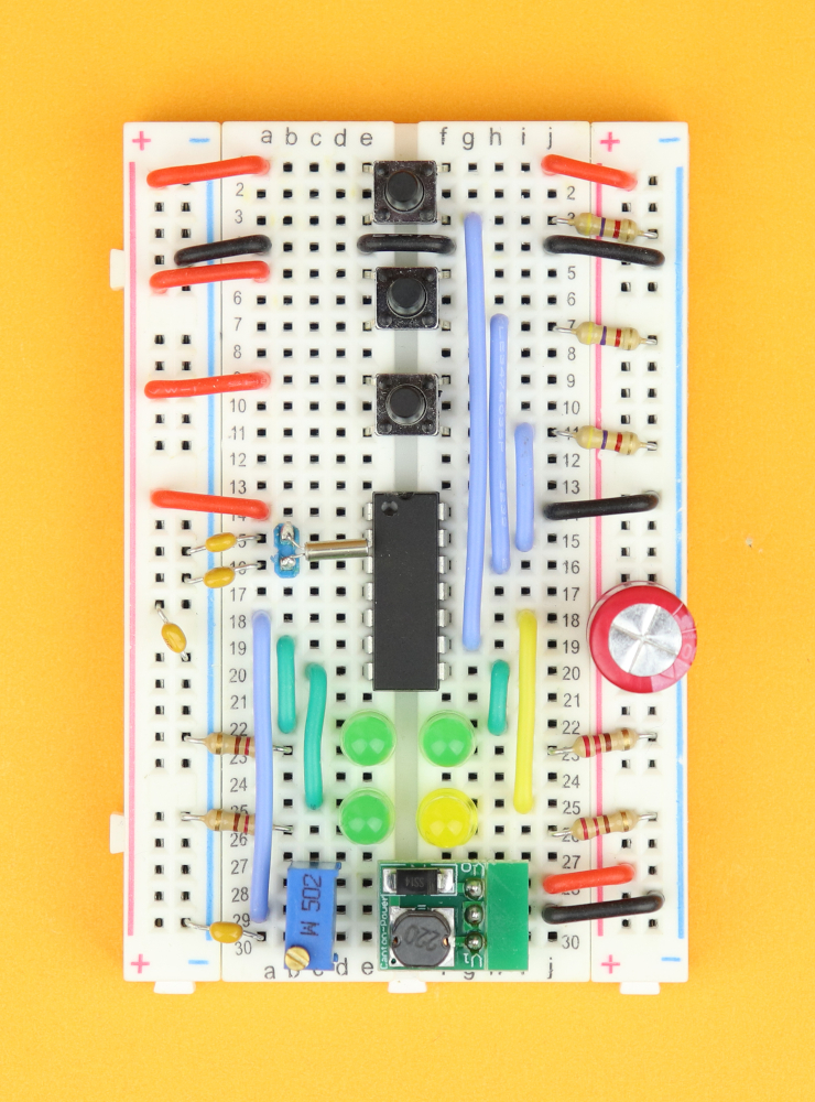
Insert the DC/DC converter module in rows 28, 29, and 30. Make sure the Vo pin is in row 28, and the V1 pin is in row 30. Connect the center pin in row 29 to the right ground rail, and connect the output pin Vo in row 28 to the positive power rail. This will supply yhe entire positive power rail with +5V.
-
-
Step 13
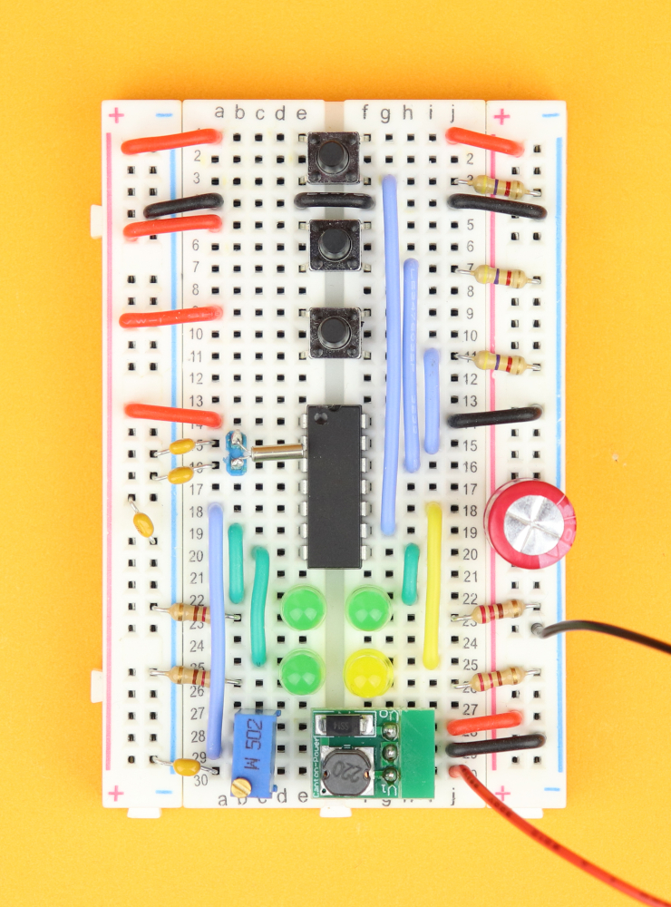
Connect the positive lead of the battery pack to the V1 pin in row 30, and connect the negative lead to the ground rail anywhere you want.
-

-
Step 14
Now it's time to connect the PICkit3 programmer.
Master clear (yellow wire) goes into pin 4, program data (blue wire) into pin 10, and program clock (green wire) into pin 9. The red wire is VDD and you can plug it into the positive power rail, and the black wire is ground, so it goes into the ground rail.
-

-
Step 15
And last, connect the panel meter. The positive terminal (blue wire) goes in row 30 on the left, and the negative terminal (black wire) can be connected to the ground rail anywhere you like.
But of course, when you connect the power, nothing happens yet, because the PIC's program memory is empty and it doesn't know what to do yet. So let's talk about that next!
Writing the software
First of all, if you are new to all of this and just want to get it working: don't worry :) You can download the ready-made .hex-file in the resources box, and then simply follow these general instructions here to flash the .hex-file onto the controller. For this you need zero programming skills, but you do need the PICkit3 programmer.
For this you also need to download the MPLAB X IDE, which is free to use for our purposes, and then follow the steps explained in the article above (or in the video) to flash the .hex-file onto the PIC16F1455:
After that you can remove the PICkit3, and the clock should be ready to use :) If that's all you are interested in, you can now skip to the next part.
But if you are interested in learning more about the program that actually makes the clock work as a clock, then keep reading. We will first go through the main ideas and concepts, and then have a detailed look at the actual code for this project (and you can download the full source code in the resources box and it is also shown in the appendix). Here it is:
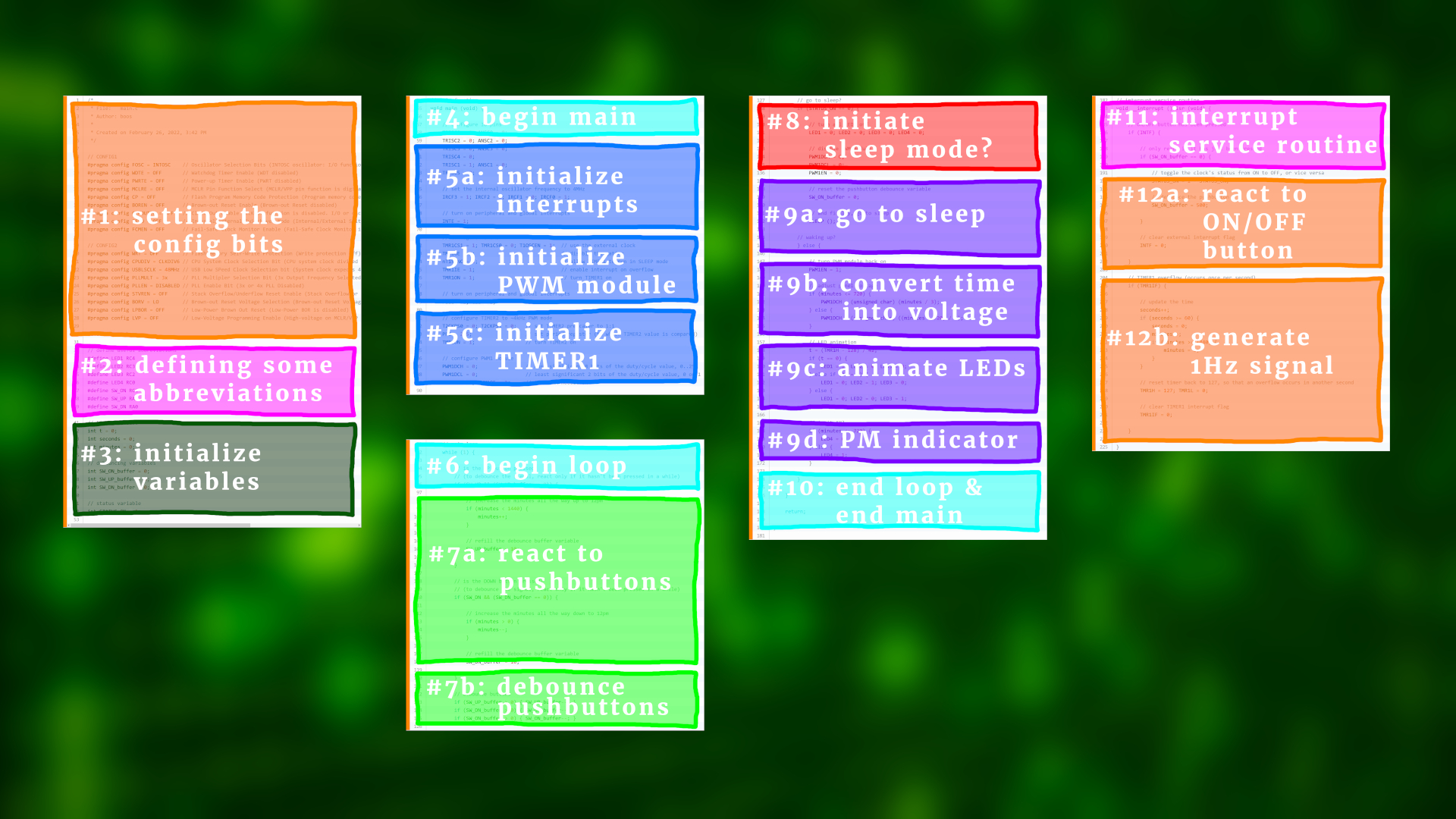
And as promised, let's first go through the main ideas.
- Sleep mode is actually very simple, it's just one instruction.
SLEEP();The controller shuts down the internal oscillator and all non-essential hardware, and typically needs less than a few microamps to run. But that's only half of the story. Because when the controller goes to sleep, we also gotta make sure it can wake up again somehow, right?

- That's where interrupts come in. Usually, the main part of a microcontroller program is a big loop that runs over and over and over again. But when an interrupt happens, the program jumps to a special part of the code: the so-called interrupt service routine. It basically drops what it is doing and jumps there as fast as it can. Then this code here is run, and after it's completed the main part of the code resumes as before.

- The good news: interrupts work in sleep mode! In our case today there are two interrupt sources: the external ON/OFF button is connected to pin RC1, which triggers an interrupt when it detects a logical HIGH signal. The other interrupt source is a timer that is connected to the watch crystal. But what is a timer?
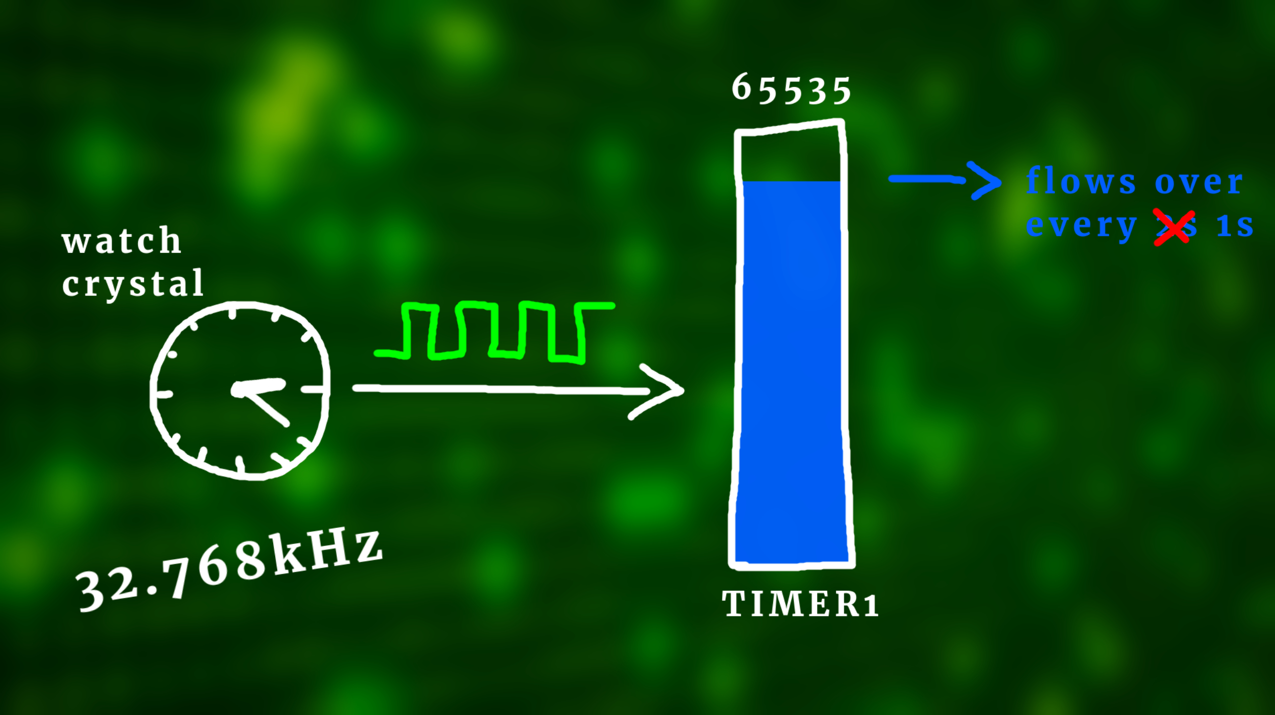
- A timer is just a counter. Timer1 can count up to 65,535, which is 16 bit. In our program we use the watch crystal to feed this timer, and because the watch crystal runs at 32.768 kHz, this timer flows over every 2 seconds. And whenever it flows over, you guessed it, it causes an interrupt! So in the interrupt service routine we can just reset the timer back to zero, or, in our case, back to 32768, because then it flows over every second, and we can use this to keep the time. This is why the watch crystal has such a weird frequency: it is literally made for this purpose. And like we said before, timer1 keeps running in sleep mode, because it uses the external crystal, so it will keep the time accurate even if the controller is in SLEEP mode.
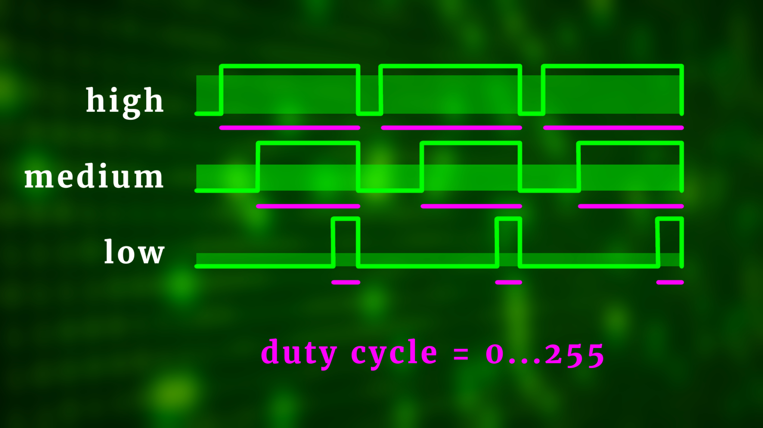
- And last, our program needs to take the time information and convert it into a voltage. For that we use pulse-width modulation or PWM for short. I have a detailed video on this, but in a nutshell, PWM creates the illusion of an analog voltage by quickly turning a digital pin on and off. The longer the pin is on, and that value is called duty cycle, the closer the apparent voltage is to 5V. In our case, the duty cycle is a number between 0 and 255.
- Now, 12 hours have 720 minutes. So if we take the minutes and divide it by 3, we have a number between 0 and 240, and 240 corresponds to a voltage of around 4.7 volts. Technically, we would have to divide by ...., but that would take the controller forever and would need much more program memory, so it's easier to just divide by 3 and then decrease the potentiometer R8 so that the display maxes out at 4.7V instead of 5V. This is a neat little trick that makes our life much easier.
And that's the main idea. Now let's jump into the details of the code. Don't forget that I also have a detailed video on the code available, if you are interested!
/*
 * File:   main.c
 * Author: boos
 *
 * Created on February 26, 2022, 3:42 PM
 */

// CONFIG1
#pragma config FOSC = INTOSC    // Oscillator Selection Bits (INTOSC oscillator: I/O function on CLKIN pin)
#pragma config WDTE = OFF       // Watchdog Timer Enable (WDT disabled)
#pragma config PWRTE = OFF      // Power-up Timer Enable (PWRT disabled)
#pragma config MCLRE = OFF      // MCLR Pin Function Select (MCLR/VPP pin function is digital input)
#pragma config CP = OFF         // Flash Program Memory Code Protection (Program memory code protection is disabled)
#pragma config BOREN = OFF      // Brown-out Reset Enable (Brown-out Reset disabled)
#pragma config CLKOUTEN = OFF   // Clock Out Enable (CLKOUT function is disabled. I/O or oscillator function on the CLKOUT pin)
#pragma config IESO = OFF       // Internal/External Switchover Mode (Internal/External Switchover Mode is disabled)
#pragma config FCMEN = OFF      // Fail-Safe Clock Monitor Enable (Fail-Safe Clock Monitor is disabled)

// CONFIG2
#pragma config WRT = OFF        // Flash Memory Self-Write Protection (Write protection off)
#pragma config CPUDIV = CLKDIV6 // CPU System Clock Selection Bit (CPU system clock divided by 6)
#pragma config USBLSCLK = 48MHz // USB Low SPeed Clock Selection bit (System clock expects 48 MHz, FS/LS USB CLKENs divide-by is set to 8.)
#pragma config PLLMULT = 3x     // PLL Multipler Selection Bit (3x Output Frequency Selected)
#pragma config PLLEN = DISABLED // PLL Enable Bit (3x or 4x PLL Disabled)
#pragma config STVREN = OFF     // Stack Overflow/Underflow Reset Enable (Stack Overflow or Underflow will not cause a Reset)
#pragma config BORV = LO        // Brown-out Reset Voltage Selection (Brown-out Reset Voltage (Vbor), low trip point selected.)
#pragma config LPBOR = OFF      // Low-Power Brown Out Reset (Low-Power BOR is disabled)
#pragma config LVP = OFF        // Low-Voltage Programming Enable (High-voltage on MCLR/VPP must be used for programming)

#include <xc.h>
In the above, we set the configuration bits of the PIC16F1455. The important details are in line 9 (where we activate the internal oscillator), line 12 (where we de-active the reset functionality on the MCLR pin), and line 28 (where we deactive low-voltage programming).
// define useful abbreviations
#define LED1 RC4
#define LED2 RC3
#define LED3 RC2
#define LED4 RC0
#define SW_ON RC1
#define SW_UP RA1
#define SW_DN RA0

// time variables
int t = 0;
int seconds = 0;
int minutes = 0;

// debouncing variables
int SW_ON_buffer = 0;
int SW_UP_buffer = 0;
int SW_DN_buffer = 0;

// status variable
int STATUS_ON = 1;
Next, we defined the locations of the LEDs, the pushbuttons, and initialized our variables that we will need later on.
// main function
void main (void) {

    // configure IO pins
    TRISC0 = 0; ANSC0 = 0;
    TRISC2 = 0; ANSC2 = 0;
    TRISC3 = 0; ANSC3 = 0;
    TRISC4 = 0;
    TRISC1 = 1; ANSC1 = 0;
    TRISC5 = 0;
Then the main function begins. I always begin by setting the tristate registers of the IO pins. The LEDs are outputs, so I am setting those to 0, and the pushbuttons are inputs, so those get set to 1. Wherever necessary I also disable the analog to digital converter functionality, because otherwise the pins digital functionality is impaired. And yes, I learned that the hard way...
    // set the internal oscillator frequency to 4MHz
    IRCF3 = 1; IRCF2 = 1; IRCF1 = 0; IRCF0 = 1;
Here we set the frequency of the internal oscillator to 4MHz, and you can find more on this in Section 5.9 on page 73 of the PIC16F1455 datasheet.
    // enable the external interrupt
    INTE = 1;
Next, we enable the external interrupt on pin RC1. It triggers whenever it detects a positive pulse.
    // configure TIMER1
    TMR1CS1 = 1; TMR1CS0 = 0; T1OSCEN = 1;	// use the external clock
    TMR1GE = 0;								// disable the gating
	nT1SYNC = 1;							// allow TIMER1 to run in SLEEP mode
	TMR1IE = 1;								// enable interrupt on overflow
	TMR1ON = 1;								// turn TIMER1 on
This part configures Timer1 to work as intended. In line 72 we make it use the watch crystal as a clock source, in line 74 we make sure that it also runs during SLEEP mode (very important!), line 75 enables an interrupt whenever the timer flows over (we need that to generate our 1Hz timebase, more on that below), and finally in line 76 we turn the timer on.
    // turn on peripheral and global interrupts
    PEIE = 1; GIE = 1;
And since we are relying on interrupts we need to enable both peripheral interrupts and global interrupts.
    // configure TIMER2 to ~4kHz PWM mode
    T2CKPS0 = 0; T2CKPS1 = 0;	// set TIMER2 prescaler to 1:1
	PR2 = 255; 					// set period register (to which TIMER2 value is compared)
	TMR2ON = 1; 				// turn TIMER2 on
This part configures Timer2 to run at 4kHz. The values are explained in Section 21 on page 190 of the PIC16F1455 datasheet.
    // configure PWM1 module
    PWM1DCH = 0;				// most significant 8 bits of the duty/cycle value, 0..255
    PWM1DCL = 0;				// least significant 2 bits of the duty/cycle value, 0 or 1
    PWM1EN = 1; PWM1OE = 1;		// turn PWM module on
Here we finish configuring the PIC16F1455's PWM module no. 1. If you want to learn more about it, check out the article on the electronic candle where we already used this module :)
    // main loop
    while (1) {
This part begins the main-loop that will be run over and over and over again.
        // is the UP button pressed?
        // (to debounce the signal, react only if it hasn't been pressed in a while)
        if (SW_UP && (SW_UP_buffer == 0)) {

            // increase the minutes all the way up to 12pm
            if (minutes < 1440) {
                minutes++;
            }

            // refill the debounce buffer variable
            SW_UP_buffer = 10;

        }
If the UP button is pressed, we increase the time, but only if we are below midnight. The variable SW_UP_buffer debounces the button digitally.
        // is the DOWN button pressed?
        // (to debounce the signal, react only if it hasn't been pressed in a while)
        if (SW_DN && (SW_DN_buffer == 0)) {

            // increase the minutes all the way down to 12pm
            if (minutes > 0) {
                minutes--;
            }

            // refill the debounce buffer variable
            SW_DN_buffer = 10;

        }
And here we decrease the time, but only if we are above midnight. Again, SW_DN_buffer is a debouncing variable.
        // debounce buttons
        if (SW_UP_buffer > 0) { SW_UP_buffer--; }
        if (SW_DN_buffer > 0) { SW_DN_buffer--; }
        if (SW_ON_buffer > 0) { SW_ON_buffer--; }
And here we clear the debouncing variables by one count at a time.
        // go to sleep?
        if (STATUS_ON == 0) {

            // turn all LEDs off
            LED1 = 0; LED2 = 0; LED3 = 0; LED4 = 0;

			// disable PWM module
            PWM1DCH = 0;
            PWM1DCL = 0;
            PWM1EN = 0;

			// reset the pushbutton debounce variable
            SW_ON_buffer = 0;

			// and finally, go to sleep
            SLEEP ();
If STATUS_ON has value 0, then the clock has been turned off. In that case we first turn all LEDs off (line 131), turn the PWM module off (lines 136-136), reset the debounce variable for the ON pushbutton (line 139), and finally go to SLEEP mode (line 142).
        // waking up?
		} else {

			// turn PWM module back on
			PWM1EN = 1;

            // adjust panel voltage
            if (minutes <= 720) {
                PWM1DCH = (unsigned char) (minutes / 3);
            } else {
                PWM1DCH = (unsigned char) ((minutes - 720) / 3);
            }

            // LED animation
    		t = (TMR1H - 128) / 42;
            if (t == 0) {
                LED1 = 1; LED2 = 0; LED3 = 0;
            } else if (t == 1) {
                LED1 = 0; LED2 = 1; LED3 = 0;
            } else {
                LED1 = 0; LED2 = 0; LED3 = 1;
            }

            // is it AM?
    		if (minutes <= 720) {
    			LED4 = 0;
    		} else {
                LED4 = 1;
            }

		}
If the variable STATUS_ON has the value 1, however, the clock is ON. Then we need to make sure the PWM module is on (line 148), and we then convert the minute count into the proper output duty/cycle value (lines 150-155). We also animate the LEDs in lines 157-165, by determining in which fraction of the second we are. And last, if it is AM we turn the PM indicator LED4 off, and if it is indeed PM, we turn LED4 on.
    }

    return;

}
And that was the main function!
// interrupt service routine
void __interrupt () isr (void) {
Now, the interrupt service routine is called whenever an interrupt happens.
    // ON/OFF button has been pressed
    if (INTF) {

        // only react if it has just been pressed
        if (SW_ON_buffer == 0) {

            // toggle the clock's status from ON to OFF, or vice versa
            STATUS_ON = 1 - STATUS_ON;

            // debounce the pushbutton
            SW_ON_buffer = 500;

        }

        // clear external interrupt flag
        INTF = 0;

    }
And if t hat interrupt is from the ON/OFF button, we toggle the clock's status from ON to OFF or from OFF to ON (line 192), but only if the debounce buffer variable SW_ON_buffer is still zero. After that we refill this variable (line 195) and then clear the external interrupt flag (line 200). This last part is very important, because if we didn't do that, the interrupt service routine would be called over and over and over again. Again, I learned this the hard way...
    // TIMER1 overflow (occurs once per second)
    if (TMR1IF) {

        // update the time
		seconds++;
		if (seconds >= 60) {
			seconds = 0;
			minutes++;
			if (minutes >= 1440) {
				minutes = 0;
			}
		}

        // reset timer back to 127, so that an overflow occurs in another second
        TMR1H = 127; TMR1L = 0;

        // clear TIMER1 interrupt flag
        TMR1IF = 0;

    }
This part is called whenever Timer1 overflows, which happens once a second the way we set up things. We can update the time, which is rather straightforward (lines 207-215), and then we need to reset the Timer1. We reset it back to 1/2 of its full scale, because this way it flows over every 1 second as opposed to every 2 seconds. This is just a matter of taste, but I like if because this way we could, in principle, use the register TMR1L (which contains the lower 8 bits of the 16 bits of Timer1) to make fine adjustments to the timing. And then, just as before, in line 221 we clear the Timer1 overflow interrupt flag.
}And... that's the end of the interrupt service routine, and I hope that this detailed explanation helped to make the code less mysterious :)
Finished clock
With the program finally on the controller we can remove the PICkit3, and our clock is finished and ready to use. And let's verify that this SLEEP mode thing really works. When the clock is up and running it uses around 100mA of current, which is quite substantial. But when the clock is turned OFF, we see that the current drops to a few microamps.
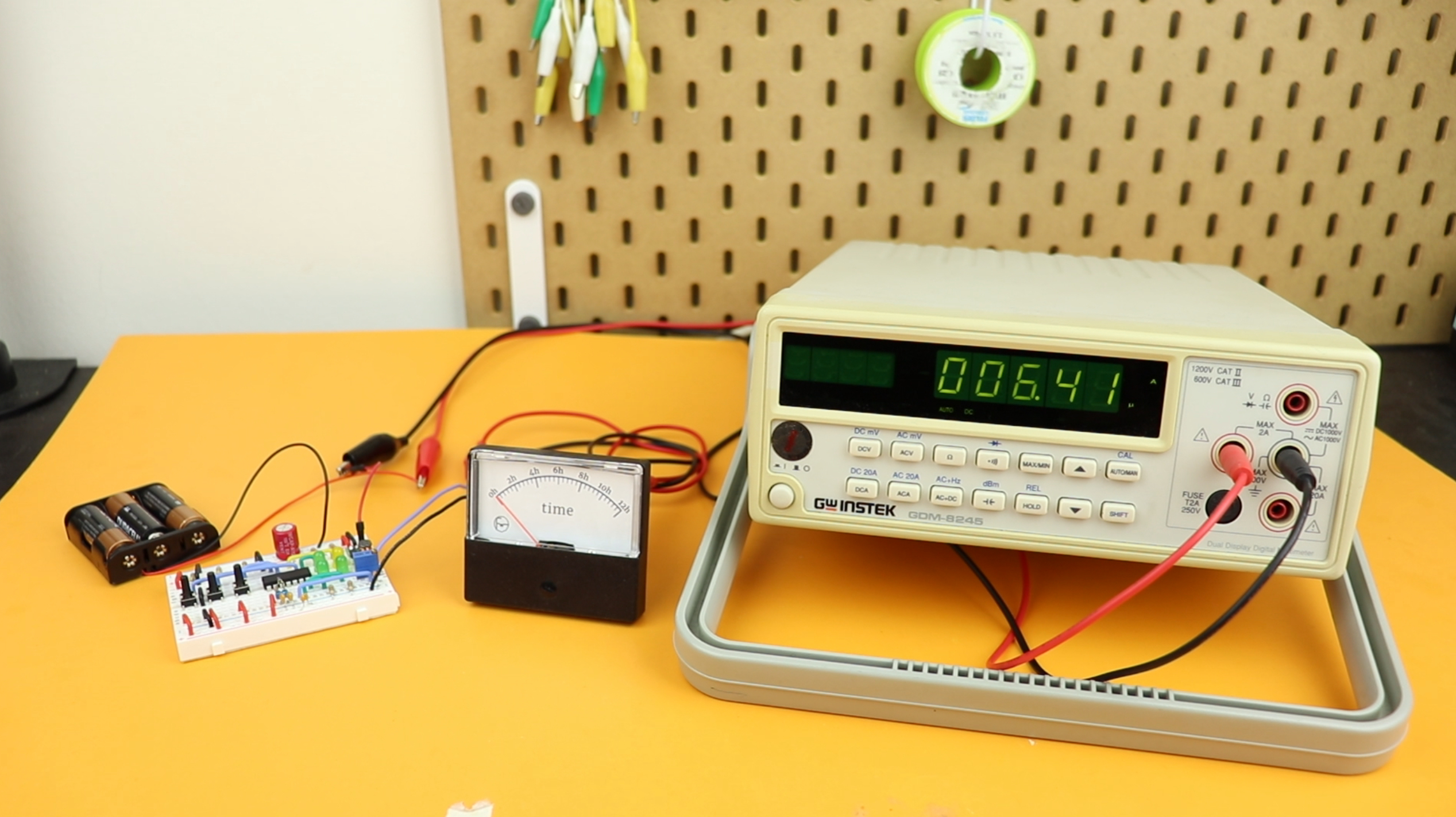
A typical AA battery has a capacity of around 2000mAh, and at 2 microamps this means the clock could run one million hours, which is more than a hundred years!
Okay, that's not realistic, because at those timescales other things become more important, but it means that this clock will definitely be OK if you put it in a drawer and forget about it for a few months.
Actually, I was curious about the accuracy of the clock, and I connected my frequency counter to the watch crystal.
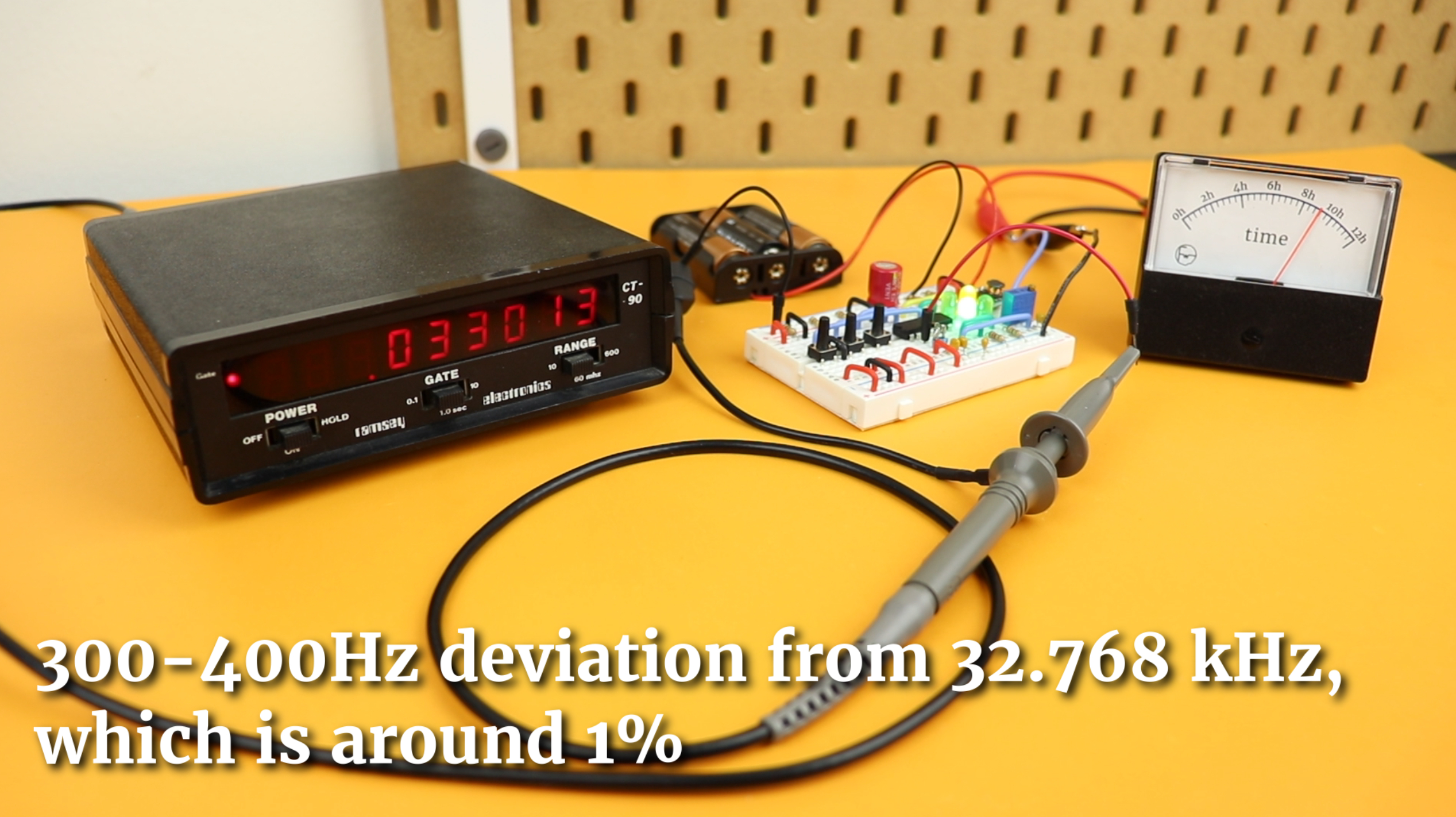
As you can see it does not really oscillate at 32.768 kHz, so the accuracy is not very good. The reason is that most crystals need a specific load capacitance, that's the two 22pF capacitors C3 and C4 in our case here. But the breadboard is made of plastic and metal and that affects the load capacitance. We could solve this by using an adjustable load capacitor, or by tackling this inaccuracy on the software side.
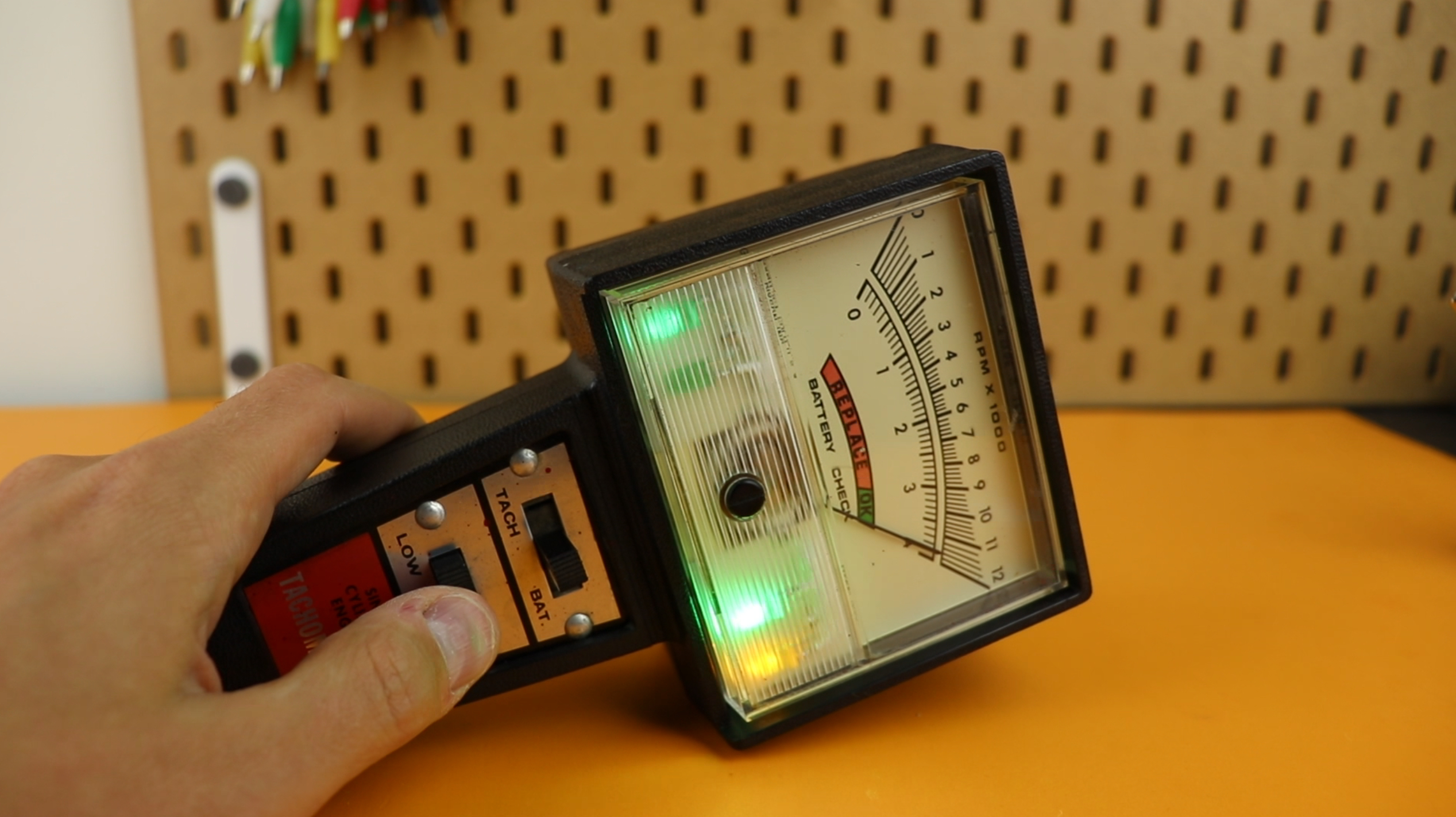
And last, for fun, I decided to build this entire project again, but on a PCB instead. I planned to fit it into one of these old-fashioned tachometers:
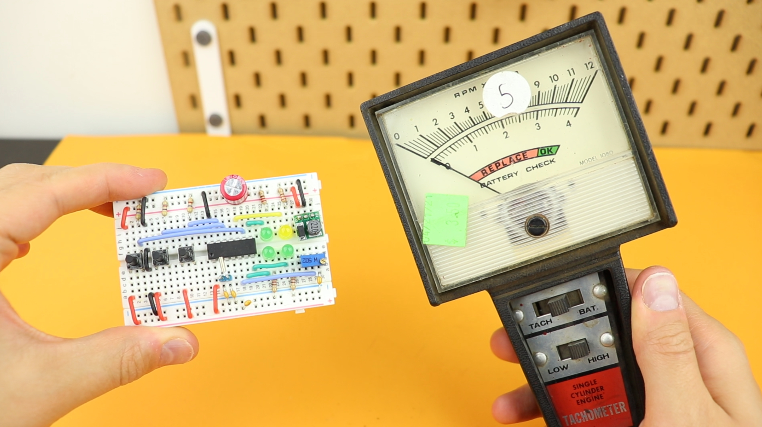
And here you can see the breadboard circuit and the PCB-circuit side by side:

Then I re-wired the switches, the panel meter, included a battery pack, and some LEDs:
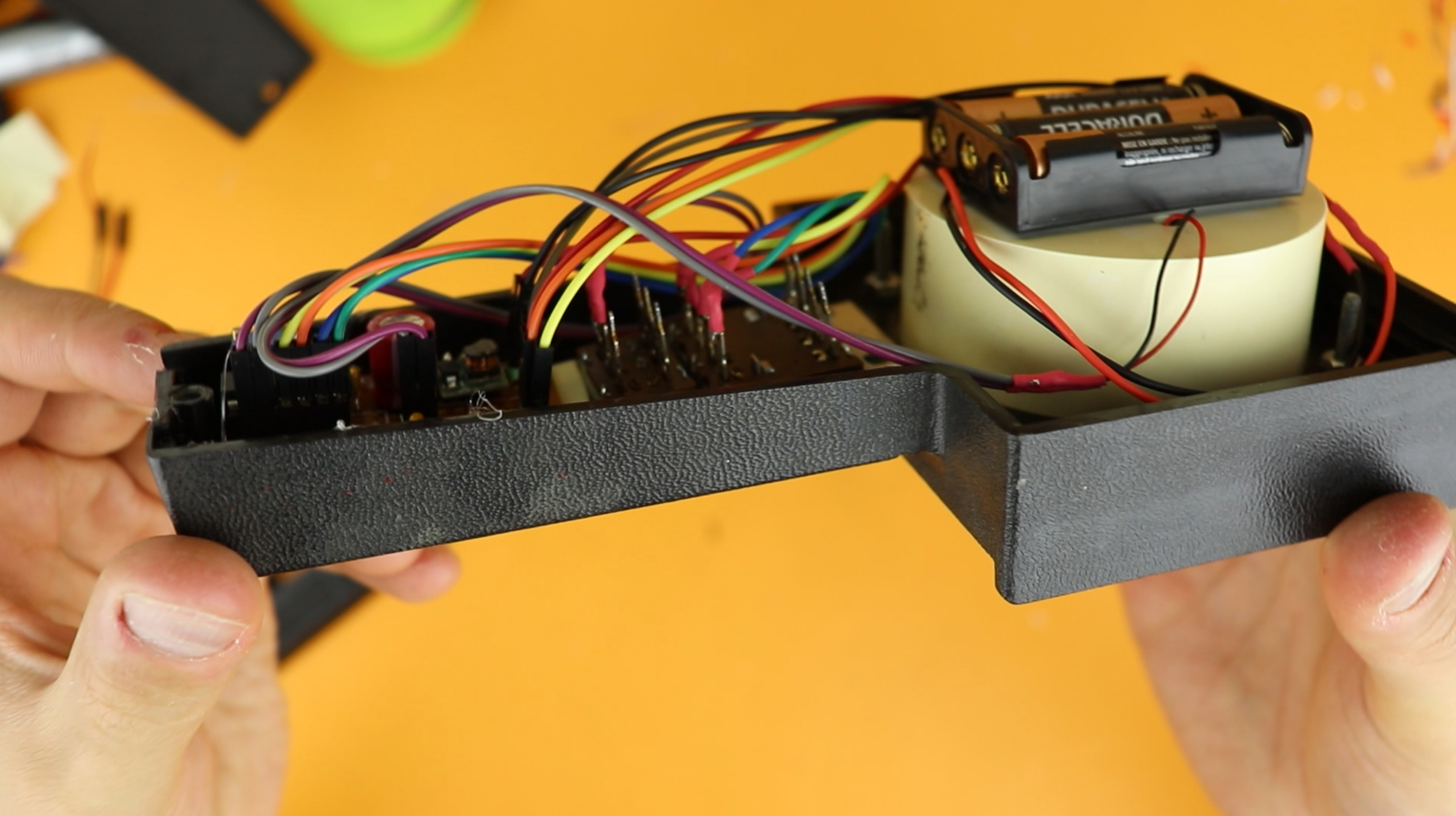
I think it turned out well, what do you think?
If you want to see the build process, check out the full video below :)
YouTube video
I covered this entire project in a dedicated YouTube video:
There is also a detailed video on the source code itself, including a step-by-step tutorial on how to write the program:
Final thoughts
This project has a lot of different parts, and that's what I like about it. If it's a bit too much, check out my other tutorials on how to get started with PIC microcontrollers, and you will see that with a bit of practice you can do it, too. And: don't forget to check out the video as well.
And last, here is something very important: if something doesn't work, or if anything in this video doesn't make sense, let me know on social media, and I will do my best to get back to you. Thank you so much for reading, and I will see you next time!
Appendix: the full source code
Here you can find the full source code. The code (as well as the .hex file) are also available for download in the resources box.
/*
 * File:   main.c
 * Author: boos
 *
 * Created on February 26, 2022, 3:42 PM
 */

// CONFIG1
#pragma config FOSC = INTOSC    // Oscillator Selection Bits (INTOSC oscillator: I/O function on CLKIN pin)
#pragma config WDTE = OFF       // Watchdog Timer Enable (WDT disabled)
#pragma config PWRTE = OFF      // Power-up Timer Enable (PWRT disabled)
#pragma config MCLRE = OFF      // MCLR Pin Function Select (MCLR/VPP pin function is digital input)
#pragma config CP = OFF         // Flash Program Memory Code Protection (Program memory code protection is disabled)
#pragma config BOREN = OFF      // Brown-out Reset Enable (Brown-out Reset disabled)
#pragma config CLKOUTEN = OFF   // Clock Out Enable (CLKOUT function is disabled. I/O or oscillator function on the CLKOUT pin)
#pragma config IESO = OFF       // Internal/External Switchover Mode (Internal/External Switchover Mode is disabled)
#pragma config FCMEN = OFF      // Fail-Safe Clock Monitor Enable (Fail-Safe Clock Monitor is disabled)

// CONFIG2
#pragma config WRT = OFF        // Flash Memory Self-Write Protection (Write protection off)
#pragma config CPUDIV = CLKDIV6 // CPU System Clock Selection Bit (CPU system clock divided by 6)
#pragma config USBLSCLK = 48MHz // USB Low SPeed Clock Selection bit (System clock expects 48 MHz, FS/LS USB CLKENs divide-by is set to 8.)
#pragma config PLLMULT = 3x     // PLL Multipler Selection Bit (3x Output Frequency Selected)
#pragma config PLLEN = DISABLED // PLL Enable Bit (3x or 4x PLL Disabled)
#pragma config STVREN = OFF     // Stack Overflow/Underflow Reset Enable (Stack Overflow or Underflow will not cause a Reset)
#pragma config BORV = LO        // Brown-out Reset Voltage Selection (Brown-out Reset Voltage (Vbor), low trip point selected.)
#pragma config LPBOR = OFF      // Low-Power Brown Out Reset (Low-Power BOR is disabled)
#pragma config LVP = OFF        // Low-Voltage Programming Enable (High-voltage on MCLR/VPP must be used for programming)

#include <xc.h>

// define useful abbreviations
#define LED1 RC4
#define LED2 RC3
#define LED3 RC2
#define LED4 RC0
#define SW_ON RC1
#define SW_UP RA1
#define SW_DN RA0

// time variables
int t = 0;
int seconds = 0;
int minutes = 0;

// debouncing variables
int SW_ON_buffer = 0;
int SW_UP_buffer = 0;
int SW_DN_buffer = 0;

// status variable
int STATUS_ON = 1;

// main function
void main (void) {

    // configure IO pins
    TRISC0 = 0; ANSC0 = 0;
    TRISC2 = 0; ANSC2 = 0;
    TRISC3 = 0; ANSC3 = 0;
    TRISC4 = 0;
    TRISC1 = 1; ANSC1 = 0;
    TRISC5 = 0;

    // set the internal oscillator frequency to 4MHz
    IRCF3 = 1; IRCF2 = 1; IRCF1 = 0; IRCF0 = 1;

	// enable the external interrupt
    INTE = 1;

    // configure TIMER1
    TMR1CS1 = 1; TMR1CS0 = 0; T1OSCEN = 1;	// use the external clock
    TMR1GE = 0;								// disable the gating
	nT1SYNC = 1;							// allow TIMER1 to run in SLEEP mode
	TMR1IE = 1;								// enable interrupt on overflow
	TMR1ON = 1;								// turn TIMER1 on

	// turn on peripheral and global interrupts
    PEIE = 1; GIE = 1;

	// configure TIMER2 to ~4kHz PWM mode
    T2CKPS0 = 0; T2CKPS1 = 0;	// set TIMER2 prescaler to 1:1
	PR2 = 255; 					// set period register (to which TIMER2 value is compared)
	TMR2ON = 1; 				// turn TIMER2 on

    // configure PWM1 module
    PWM1DCH = 0;				// most significant 8 bits of the duty/cycle value, 0..255
    PWM1DCL = 0;				// least significant 2 bits of the duty/cycle value, 0 or 1
    PWM1EN = 1; PWM1OE = 1;		// turn PWM module on

    // main loop
    while (1) {

        // is the UP button pressed?
        // (to debounce the signal, react only if it hasn't been pressed in a while)
        if (SW_UP && (SW_UP_buffer == 0)) {

            // increase the minutes all the way up to 12pm
            if (minutes < 1440) {
                minutes++;
            }

            // refill the debounce buffer variable
            SW_UP_buffer = 10;

        }

        // is the DOWN button pressed?
        // (to debounce the signal, react only if it hasn't been pressed in a while)
        if (SW_DN && (SW_DN_buffer == 0)) {

            // increase the minutes all the way down to 12pm
            if (minutes > 0) {
                minutes--;
            }

            // refill the debounce buffer variable
            SW_DN_buffer = 10;

        }

        // debounce buttons
        if (SW_UP_buffer > 0) { SW_UP_buffer--; }
        if (SW_DN_buffer > 0) { SW_DN_buffer--; }
        if (SW_ON_buffer > 0) { SW_ON_buffer--; }

        // go to sleep?
        if (STATUS_ON == 0) {

            // turn all LEDs off
            LED1 = 0; LED2 = 0; LED3 = 0; LED4 = 0;

			// disable PWM module
            PWM1DCH = 0;
            PWM1DCL = 0;
            PWM1EN = 0;

			// reset the pushbutton debounce variable
            SW_ON_buffer = 0;

			// and finally, go to sleep
            SLEEP ();

		// waking up?
		} else {

			// turn PWM module back on
			PWM1EN = 1;

            // adjust panel voltage
            if (minutes <= 720) {
                PWM1DCH = (unsigned char) (minutes / 3);
            } else {
                PWM1DCH = (unsigned char) ((minutes - 720) / 3);
            }

            // LED animation
    		t = (TMR1H - 128) / 42;
            if (t == 0) {
                LED1 = 1; LED2 = 0; LED3 = 0;
            } else if (t == 1) {
                LED1 = 0; LED2 = 1; LED3 = 0;
            } else {
                LED1 = 0; LED2 = 0; LED3 = 1;
            }

            // is it AM?
    		if (minutes <= 720) {
    			LED4 = 0;
    		} else {
                LED4 = 1;
            }

		}

    }

    return;

}

// interrupt service routine
void __interrupt () isr (void) {

    // ON/OFF button has been pressed
    if (INTF) {

        // only react if it has just been pressed
        if (SW_ON_buffer == 0) {

            // toggle the clock's status from ON to OFF, or vice versa
            STATUS_ON = 1 - STATUS_ON;

            // debounce the pushbutton
            SW_ON_buffer = 500;

        }

        // clear external interrupt flag
        INTF = 0;

    }

    // TIMER1 overflow (occurs once per second)
    if (TMR1IF) {

        // update the time
		seconds++;
		if (seconds >= 60) {
			seconds = 0;
			minutes++;
			if (minutes >= 1440) {
				minutes = 0;
			}
		}

        // reset timer back to 127, so that an overflow occurs in another second
        TMR1H = 127; TMR1L = 0;

        // clear TIMER1 interrupt flag
        TMR1IF = 0;

    }

}


